EP1102421A2 - Méthode et système pour éviter les pics périodiques d'interférence dans une communication sans fil entre une station mobile et une station de base - Google Patents
Méthode et système pour éviter les pics périodiques d'interférence dans une communication sans fil entre une station mobile et une station de base Download PDFInfo
- Publication number
- EP1102421A2 EP1102421A2 EP00310200A EP00310200A EP1102421A2 EP 1102421 A2 EP1102421 A2 EP 1102421A2 EP 00310200 A EP00310200 A EP 00310200A EP 00310200 A EP00310200 A EP 00310200A EP 1102421 A2 EP1102421 A2 EP 1102421A2
- Authority
- EP
- European Patent Office
- Prior art keywords
- base unit
- power supply
- frequency
- mobile unit
- interference
- Prior art date
- Legal status (The legal status is an assumption and is not a legal conclusion. Google has not performed a legal analysis and makes no representation as to the accuracy of the status listed.)
- Granted
Links
Images


Classifications
-
- H—ELECTRICITY
- H04—ELECTRIC COMMUNICATION TECHNIQUE
- H04W—WIRELESS COMMUNICATION NETWORKS
- H04W52/00—Power management, e.g. Transmission Power Control [TPC] or power classes
- H04W52/04—Transmission power control [TPC]
-
- H—ELECTRICITY
- H04—ELECTRIC COMMUNICATION TECHNIQUE
- H04B—TRANSMISSION
- H04B1/00—Details of transmission systems, not covered by a single one of groups H04B3/00 - H04B13/00; Details of transmission systems not characterised by the medium used for transmission
- H04B1/06—Receivers
- H04B1/10—Means associated with receiver for limiting or suppressing noise or interference
- H04B1/1027—Means associated with receiver for limiting or suppressing noise or interference assessing signal quality or detecting noise/interference for the received signal
Definitions
- This invention relates generally to the field of telecommunications and, more specifically, to a method and system for avoiding periodic bursts of interference in wireless communication between a mobile unit and a base unit.
- Wireless telephone systems are also known as portable, cordless or mobile telephone systems.
- a typical wireless communication system has a base station located at a customer's or user's premises. The base is connected to the Public Switched Telephone Network (PSTN) over a wireline interface and communicates with a mobile unit or handset over an air interface that permits the user to communicate remotely from the base station.
- PSTN Public Switched Telephone Network
- users desire the freedom and flexibility afforded by mobile wireless communications systems, they typically do not want to sacrifice the numerous features, such as caller ID, that are available through the wireline service over the PSTN.
- users of wireless systems increasingly demand a voice quality that is as good as the voice quality available over a wireline link.
- wireless communication devices and methods have provided an improvement over prior approaches in terms of features, voice quality, cost, packaging size and weight, the challenges in the field of wireless telecommunications have continued to increase with demands for more and better techniques having greater flexibility and adaptability.
- Embodiments of the present invention aim to provide a method and system for interfacing a mobile unit and a base unit of a wireless communication system in the presence of a periodically bursted interferer in which disadvantages and problems associated with previously developed systems and methods are reduced or substantially eliminated.
- a method for interfacing telecommunication devices is disclosed.
- a base unit is connected to a landline for wireless communication.
- the base unit has a power supply operating at a power supply frequency.
- a mobile unit is provided for wireless communication with the base unit.
- the base unit is interfaced to the mobile unit using an interface protocol that has a plurality of frames.
- Each frame is for transmitting signals from the mobile unit to the base unit and from the base unit to the mobile unit.
- the frames have a specified frame length.
- An interference frequency is detected at either the base unit or the mobile unit.
- the interference frequency is compared with the power supply frequency.
- the frames are synchronized with the power supply and the specified frame length is adjusted based on the power supply frequency when the interference frequency and the power supply frequency are substantially the same.
- inventions of the present invention include providing for interfacing a mobile unit and a base unit in the presence of a periodically bursted interferer.
- the interference frequency of the interferer is compared to the power supply frequency for the base unit. Accordingly, the system is able to determine that the interference is due to a periodically bursted interferer.
- the frame length of frames for communicating data between the units may be adjusted in accordance with the power supply frequency such that the interference is avoided.
- FIGURES 1 through 5 of the drawings like numerals being used for like and corresponding parts of the various drawings.
- FIGURE 1 is a block diagram illustrating a telecommunication system 10 including a base unit 12 and a mobile unit 14.
- the base unit 12 and the mobile unit 14 communicate with each other at a frequency in the industrial/scientific/medical (ISM) band.
- ISM industrial/scientific/medical
- the units 12 and 14 may communicate in the range of 2400 to 2483.5 MHz. It will be understood, however, that the base unit 12 and the mobile unit 14 may communicate with each other at other suitable frequencies without departing from the scope of the present invention.
- the telecommunication system 10 illustrated in FIGURE 1 is a wireless or cordless telephone system.
- the mobile unit 14 comprises a mobile handset that communicates with the base unit 12 over discreet radio frequency channels.
- the telecommunication system 10 is illustrated as a cordless telephone system, it will be understood that the telecommunication system 10 may comprise any suitable type of wireless communication system.
- the telecommunication system 10 may comprise a cellular telephone system, Local Multiple Distribution Service, and the like, without departing from the scope of the present invention.
- the base unit 12 comprises a phone line 20 that is coupled to the Public Switched Telephone Network over a landline for receiving and transmitting voice or other data.
- data from the phone line 20 is passed to a microprocessor 24 and a caller ID interface 26.
- the caller ID interface 26 extracts caller ID information, such as a name and a telephone number associated with the originator of the telephone call, from the data on the phone line 20 and passes it to the microprocessor 24.
- the microprocessor 24 communicates with an internal memory 30 while processing the data received from the phone line 20 and the caller ID interface 26.
- the microprocessor 24 then communicates the processed data from the phone line 20 and the caller ID interface 26, along with any additional data that needs to be transmitted to the mobile unit 14, to a burst mode controller (BMC) 22.
- the BMC 22 also receives data directly from the phone line 20, which is processed along with the data from the microprocessor 24.
- the BMC 22 packages voice data from the phone line 20 with additional data from the microprocessor 24 into one frame structure.
- the BMC 22 also communicates the data to a transceiver 32 which transmits a signal through an antenna 34 to the mobile unit 14.
- the base unit 12 also comprises a keyboard 38 for inputting data to the microprocessor 24.
- the keyboard 38 may comprise a numeric keypad for entering a telephone number or other data.
- the keyboard 38 may also comprise a pager button for paging the mobile unit 14 such that the mobile unit 14 provides a sound for locating the mobile unit 14.
- the mobile unit 14 receives the signal from the base unit 12 through an antenna 50 which passes the data to a transceiver 52.
- the transceiver 52 processes the data and it to a BMC 54, which unpackages the data and communicates with a microprocessor 56.
- the microprocessor 56 communicates with an internal memory 58 and sends data to a display 60, such as an LCD or LED.
- the microprocessor 56 may send to the display 60 a name and a telephone number extracted by the caller ID interface 26 in the base unit 12.
- the BMC 54 also sends a signal to a ringer 62 to notify a user of an incoming call. After the user responds by activating the mobile unit 14, the BMC 54 sends the voice data received from the base unit 12 to an earpiece 64. After the connection is completed, voice data for transmission to the phone line 20 through the base unit 12 is received by the BMC 54 from the microphone 66. This data is transmitted from the mobile unit 14 to the base unit 12 in a similar manner to the transmission of data from the phone line 20 to the earpiece 64.
- the mobile unit 14 also comprises a keyboard 70 for a user to enter information for communication to the microprocessor 56. This keyboard 70 may be, for example, a numeric keypad on a mobile telephone handset for entering a telephone number.
- the same process is also used for an outgoing telephone call, beginning with the activation of the mobile unit 14, which sends a signal through the BMC 54 to the transceiver 52 and from the transceiver 52 to the antenna 50. From the antenna 50 of the mobile unit 14 the signal is transmitted to the antenna 34 of the base unit 12, which passes the signal to the transceiver 32. The transceiver 32 passes the signal through the BMC 22 to the phone line 20. The telephone number being called, voice and other data is then communicated back and forth between the mobile unit 14 and the base unit 12 as previously described.
- the microprocessors 24 and 56 each comprise an air interface that includes an interface protocol for interfacing the base unit 12 and the mobile unit 14.
- the interface protocol includes a plurality of consecutive frames for providing communication between the base unit 12 and the mobile unit 14, as described in more detail below in connection with FIGURE 2.
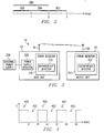
- FIGURE 2 is a timeline illustrating the length of a frame 300 in accordance with one embodiment of the present invention.
- the frame 300 has a frame length of two milliseconds.
- This two-millisecond frame 300 is sub-divided into a one-millisecond master sub-frame 302 and a one-millisecond slave sub-frame 304.
- the master sub-frame 302 is that portion of the frame 300 during which the mobile unit 14 transmits a signal to the base unit 12 and the base unit 12 receives the signal from the mobile unit 14.
- the slave sub-frame 304 is that part of the frame 300 during which the base unit 12 transmits a signal to the mobile unit 14 and the mobile unit 14 receives the signal from the base unit 12.
- each frame 300 is followed by a consecutive frame 300 such that a plurality of consecutive frames 300 provides alternating master sub-frames 302 and slave sub-frames 304.
- each master sub-frame 302 is followed by a slave sub-frame 304 which is followed by another master sub-frame 302 and so on.
- These alternating sub-frames 302 and 304 continue indefinitely while the base unit 12 and the mobile unit 14 are actively communicating.
- FIGURE 3 is a block diagram of one embodiment of the telecommunication system 10 of FIGURE 1 including a system for interfacing the base unit 12 and the mobile unit 14.
- the base unit 12 has an error detector 330 that includes an interference detector 332 for detecting interference that affects communication between the units 12 and 14.
- the base unit 12 also has a power supply detector 336 for detecting the frequency of an external power supply 338.
- the mobile unit 14 also comprises an error detector 350 that includes an interference detector 352.
- FIGURE 4 is a graph of energy versus time for a periodically bursted interferer that may interfere with communication between the base unit 12 and the mobile unit 14.
- This interference may come from any device operating in the ISM band.
- a microwave oven may act as a periodically bursted interferer when operating in the presence of a base unit 12 or a mobile unit 14.
- a periodically bursted interferer as shown in FIGURE 4, alternates between high energy levels 400 and low energy levels 402 at a specific frequency.
- the periodically bursted interferer is operating at 60 Hz, which is the standard power frequency available from power outlets in the United States.
- the periodically bursted interferer alternates between high energy levels 400 and low energy levels 402 approximately every 8 milliseconds.
- the periodically bursted interferer may operate at any suitable frequency, such as at the 50-Hz European standard, without departing from the scope of the present invention.
- the error detector 330 detects an error because of interference from a periodically bursted interferer in the presence of the base unit 12.
- the interference detector 332 determines that the error detected by the error detector 330 is due to interference, as opposed to another unidentified cause.
- the interference detector 332 determines whether the periodically bursted interferer is receiving power from the same type of power supply as the base unit 12 by comparing the interference frequency to the frequency of the external power supply 338 as detected by the power supply detector 336. If the frequencies are the same, the frame length of the frames 300 is adjusted to correspond to the power supply frequency. Thus, the frame length of each frame 300 is adjusted from two milliseconds to 16 milliseconds for the embodiment in which the periodically bursted interferer is operating at 60 Hz.
- the frames 300 are synchronized with the external power supply 338, and thus with the interferer, such that the base unit 12 transmits signals to the mobile unit 14 while the interferer is producing high energy levels 400, and the base unit 12 receives signals from the mobile unit 14 while the interferer is producing low energy levels 402.
- the high energy levels 400 in this embodiment correspond to the slave sub-frame 304 and the low energy levels 402 correspond to the master sub-frame 302.
- the frame length continues to be 16 milliseconds until the interference detector 332 no longer detects interference from the periodically bursted interferer. At this point, the frame length is adjusted to the original frame length of two milliseconds.
- the error detector 350 detects an error.
- the interference detector 352 determines that the error detected by the error detector 350 is due to interference, as opposed to another unidentified cause.
- the interference detector 352 determines whether the periodically bursted interferer is receiving power from the same type of power supply as the base unit 12. This is accomplished by comparing the interference frequency to the frequency of the external power supply 338 as detected by the power supply detector 336, which is communicated by the base unit 12 to the mobile unit 14. If the frequencies are the same, the frame length of the frames 300 is adjusted to correspond to the power supply frequency. Thus, the frame length of each frame 300 is adjusted from two milliseconds to 16 milliseconds for the embodiment in which the periodically bursted interferer is operating at 60 Hz.
- the frames 300 are synchronized with the external power supply 338, and thus with the interferer, such that the mobile unit 14 transmits signals to the base unit 12 while the interferer is producing high energy levels 400, and the mobile unit 14 receives signals from the base unit 12 while the interferer is producing low energy levels 402.
- the high energy levels 400 in this embodiment correspond to the master sub-frame 302 and the low energy levels 402 correspond to the slave sub-frame 304.
- the frame length continues to be 16 milliseconds until the interference detector 352 no longer detects interference from the periodically bursted interferer. At this point, the frame length is adjusted to the original frame length of two milliseconds.
- the periodically bursted interferer and the external power supply 338 operate at the same frequency.
- the sub-frames 302 and 304 may be correctly synchronized with the energy levels 400 and 402 based on the timing and the frequency of the signal from the external power supply 338, which corresponds to a power supply to the periodically bursted interferer.
- FIGURE 5 is a flow diagram demonstrating one method for interfacing the base unit 12 and the mobile unit 14 in the presence of a periodically bursted interferer.
- the method begins at Step 500 where the interference detector 332 detects interference with the communication between the base unit 12 and the mobile unit 14.
- an interference frequency associated with the interference is detected by the interference detector 332 and compared to a power supply frequency detected by the power supply detector 336.
- the interference detector 332 determines whether the interference frequency and the power supply frequency are the same. If the interference frequency and the power supply frequency are determined not to be the same, the method follows the No branch from decisional Step 504 to Step 506 where standard error handling techniques are used by the error detector 330 to overcome the detected error. However, if the interference frequency and the power supply frequency are determined to be the same, the method follows the Yes branch from decisional Step 504 to Step 508 where the frame length is adjusted to correspond to the power supply frequency and, thus, to the interference frequency as well.
- the interference detector 332 determines whether there is continuing interference from the periodically bursted interferer. If there is continuing interference, the method follows the Yes branch from decisional Step 510 and remains at decisional Step 510 such that the frame length continues to correspond to the power supply frequency. However, if the interference no longer exists, the method follows the No branch from decisional Step 510 to Step 512 where the frame length is adjusted to the original frame length, at which point the method ends.
Landscapes
- Engineering & Computer Science (AREA)
- Computer Networks & Wireless Communication (AREA)
- Signal Processing (AREA)
- Mobile Radio Communication Systems (AREA)
- Near-Field Transmission Systems (AREA)
Applications Claiming Priority (2)
| Application Number | Priority Date | Filing Date | Title |
|---|---|---|---|
| US09/443,931 US6496498B1 (en) | 1999-11-19 | 1999-11-19 | Method and system for avoiding periodic bursts of interference in wireless communication between a mobile unit and a base unit |
| US443931 | 1999-11-19 |
Publications (3)
| Publication Number | Publication Date |
|---|---|
| EP1102421A2 true EP1102421A2 (fr) | 2001-05-23 |
| EP1102421A3 EP1102421A3 (fr) | 2003-04-23 |
| EP1102421B1 EP1102421B1 (fr) | 2007-08-22 |
Family
ID=23762767
Family Applications (1)
| Application Number | Title | Priority Date | Filing Date |
|---|---|---|---|
| EP00310200A Expired - Lifetime EP1102421B1 (fr) | 1999-11-19 | 2000-11-16 | Méthode et système pour éviter les pics périodiques d'interférence dans une communication sans fil entre une station mobile et une station de base |
Country Status (4)
| Country | Link |
|---|---|
| US (1) | US6496498B1 (fr) |
| EP (1) | EP1102421B1 (fr) |
| DE (1) | DE60036066T2 (fr) |
| ES (1) | ES2292410T3 (fr) |
Cited By (1)
| Publication number | Priority date | Publication date | Assignee | Title |
|---|---|---|---|---|
| EP2477444A4 (fr) * | 2009-09-11 | 2013-06-26 | Panasonic Corp | Dispositif de communication sans fil |
Families Citing this family (9)
| Publication number | Priority date | Publication date | Assignee | Title |
|---|---|---|---|---|
| JP2000307749A (ja) * | 1999-04-20 | 2000-11-02 | Sharp Corp | 携帯無線機 |
| US6711380B1 (en) * | 2000-05-25 | 2004-03-23 | Motorola, Inc. | Method and apparatus for reducing interference effects caused by microwave sources |
| US20020086639A1 (en) * | 2000-12-28 | 2002-07-04 | Siemens Information And Communication Products, Inc. | Air interface frame structure for environments with bursted interference |
| CA2620893C (fr) * | 2005-09-23 | 2015-06-23 | Slipstream Data Inc. | Procede, systeme et programme informatique de separation de couleur contrainte par entropie pour images de palette avec separation par couleur |
| US8130856B1 (en) * | 2006-03-15 | 2012-03-06 | Nextel Communications Inc. | Adjustable transmit diversity |
| US9143009B2 (en) * | 2007-02-01 | 2015-09-22 | The Chamberlain Group, Inc. | Method and apparatus to facilitate providing power to remote peripheral devices for use with a movable barrier operator system |
| US7965786B2 (en) * | 2007-02-22 | 2011-06-21 | Stmicroelectronics, Inc. | Clean sensing for dynamic frequency hopping in dynamic spectrum access networks |
| US8437314B2 (en) | 2007-02-22 | 2013-05-07 | Stmicroelectronics, Inc. | Radio frequency architecture for spectrum access networks |
| US8060681B2 (en) | 2007-11-27 | 2011-11-15 | Microsoft Corporation | Interface protocol and API for a wireless transceiver |
Family Cites Families (8)
| Publication number | Priority date | Publication date | Assignee | Title |
|---|---|---|---|---|
| JPH07284141A (ja) * | 1994-04-08 | 1995-10-27 | Oki Electric Ind Co Ltd | ハンドオーバ方法 |
| US5574979A (en) * | 1994-06-03 | 1996-11-12 | Norand Corporation | Periodic interference avoidance in a wireless radio frequency communication system |
| GB2301734B (en) * | 1995-05-31 | 1999-10-20 | Motorola Ltd | Communications system and method of operation |
| US5790939A (en) * | 1995-06-29 | 1998-08-04 | Hughes Electronics Corporation | Method and system of frame timing synchronization in TDMA based mobile satellite communication system |
| GB2309857B (en) * | 1996-01-31 | 2000-08-30 | Nokia Mobile Phones Ltd | Radio telephones and method of operation |
| US6035199A (en) * | 1997-04-10 | 2000-03-07 | Hughes Electronics Corporation | Method and apparatus for performing a handoff in a wireless communication system |
| US6006071A (en) * | 1998-01-12 | 1999-12-21 | Intersil Corporation | RF communications system operable in the presence of a repetitive interference source and related methods |
| SE512034C2 (sv) * | 1998-05-11 | 2000-01-17 | Ericsson Telefon Ab L M | Förfarande och anordning för synkronisering av noder |
-
1999
- 1999-11-19 US US09/443,931 patent/US6496498B1/en not_active Expired - Lifetime
-
2000
- 2000-11-16 ES ES00310200T patent/ES2292410T3/es not_active Expired - Lifetime
- 2000-11-16 DE DE60036066T patent/DE60036066T2/de not_active Expired - Lifetime
- 2000-11-16 EP EP00310200A patent/EP1102421B1/fr not_active Expired - Lifetime
Cited By (2)
| Publication number | Priority date | Publication date | Assignee | Title |
|---|---|---|---|---|
| EP2477444A4 (fr) * | 2009-09-11 | 2013-06-26 | Panasonic Corp | Dispositif de communication sans fil |
| US8559548B2 (en) | 2009-09-11 | 2013-10-15 | Panasonic Corporation | Wireless communication apparatus |
Also Published As
| Publication number | Publication date |
|---|---|
| DE60036066T2 (de) | 2008-02-28 |
| ES2292410T3 (es) | 2008-03-16 |
| EP1102421B1 (fr) | 2007-08-22 |
| EP1102421A3 (fr) | 2003-04-23 |
| US6496498B1 (en) | 2002-12-17 |
| DE60036066D1 (de) | 2007-10-04 |
Similar Documents
| Publication | Publication Date | Title |
|---|---|---|
| CA1308183C (fr) | Configuration d'un systeme de pax sans fil et methode de communication connexe | |
| US6466800B1 (en) | Method and system for a wireless communication system incorporating channel selection algorithm for 2.4 GHz direct sequence spread spectrum cordless telephone system | |
| EP0609422A1 (fr) | Communications entre dispositifs portatifs dans un systeme telephonique sans fil | |
| JPH09331576A (ja) | 携帯電話利用制限方式および携帯電話機 | |
| JPH07303278A (ja) | 無線通信システム中で動作する無線基地局及びその制御方法 | |
| US5594737A (en) | Arrangement for controlling a transmitting/receiving device of base stations and/or mobile units, in particular of a cordless telephone system | |
| EP1463246A1 (fr) | Communication de données conversationnelles entre terminaux sur une liaison radio | |
| US6496498B1 (en) | Method and system for avoiding periodic bursts of interference in wireless communication between a mobile unit and a base unit | |
| JPS6333022A (ja) | 移動通信システム | |
| AU5000700A (en) | System and method for operating a mobile station in voice mode or pager mode | |
| US6493560B1 (en) | Method and system for changing states in a wireless telecommunication system | |
| WO2001037456A1 (fr) | Procede et systeme de radiocommunications entre une unite mobile et une base | |
| AU633190B2 (en) | Method and system for establishing link with wireless telephone | |
| US6278742B1 (en) | Method and system for power-conserving interference avoidance in communication between a mobile unit and a base unit in a wireless telecommunication system | |
| CA2150823A1 (fr) | Methode et appareil pour reduire le bruit durant la resynchronisation d'un systeme de communication numerique | |
| JP3033407B2 (ja) | 移動体間の通話システム | |
| US6118981A (en) | Wireless local loop system for radio communication between central telephone exchange and fixed subscriber | |
| JP3150096B2 (ja) | 移動体通信システム | |
| KR100299029B1 (ko) | 무선가입자망 시스템의 호 접속방법 | |
| JP3028007B2 (ja) | 移動体通信システム | |
| JP2781759B2 (ja) | 無線電話装置 | |
| WO1999031857A1 (fr) | Reseau de telephonie multiligne pour traiter les messages entrants d'identification de l'appelant | |
| JPH1169430A (ja) | 構内電子交換機 | |
| JP2648128B2 (ja) | Mca用交換機接続装置 | |
| JPH0669866A (ja) | 無線電話装置 |
Legal Events
| Date | Code | Title | Description |
|---|---|---|---|
| PUAI | Public reference made under article 153(3) epc to a published international application that has entered the european phase |
Free format text: ORIGINAL CODE: 0009012 |
|
| AK | Designated contracting states |
Kind code of ref document: A2 Designated state(s): AT BE CH CY DE DK ES FI FR GB GR IE IT LI LU MC NL PT SE TR |
|
| AX | Request for extension of the european patent |
Free format text: AL;LT;LV;MK;RO;SI |
|
| PUAL | Search report despatched |
Free format text: ORIGINAL CODE: 0009013 |
|
| AK | Designated contracting states |
Designated state(s): AT BE CH CY DE DK ES FI FR GB GR IE IT LI LU MC NL PT SE TR |
|
| AX | Request for extension of the european patent |
Extension state: AL LT LV MK RO SI |
|
| 17P | Request for examination filed |
Effective date: 20030708 |
|
| AKX | Designation fees paid |
Designated state(s): DE ES FR GB IT NL |
|
| RAP1 | Party data changed (applicant data changed or rights of an application transferred) |
Owner name: SIEMENS COMMUNICATION, INC. |
|
| GRAP | Despatch of communication of intention to grant a patent |
Free format text: ORIGINAL CODE: EPIDOSNIGR1 |
|
| GRAA | (expected) grant |
Free format text: ORIGINAL CODE: 0009210 |
|
| GRAS | Grant fee paid |
Free format text: ORIGINAL CODE: EPIDOSNIGR3 |
|
| AK | Designated contracting states |
Kind code of ref document: B1 Designated state(s): DE ES FR GB IT NL |
|
| REG | Reference to a national code |
Ref country code: GB Ref legal event code: FG4D |
|
| REF | Corresponds to: |
Ref document number: 60036066 Country of ref document: DE Date of ref document: 20071004 Kind code of ref document: P |
|
| RAP2 | Party data changed (patent owner data changed or rights of a patent transferred) |
Owner name: SIEMENS COMMUNICATIONS, INC. |
|
| NLT2 | Nl: modifications (of names), taken from the european patent patent bulletin |
Owner name: SIEMENS COMMUNICATIONS, INC. Effective date: 20071205 |
|
| REG | Reference to a national code |
Ref country code: ES Ref legal event code: FG2A Ref document number: 2292410 Country of ref document: ES Kind code of ref document: T3 |
|
| ET | Fr: translation filed | ||
| PLBE | No opposition filed within time limit |
Free format text: ORIGINAL CODE: 0009261 |
|
| STAA | Information on the status of an ep patent application or granted ep patent |
Free format text: STATUS: NO OPPOSITION FILED WITHIN TIME LIMIT |
|
| 26N | No opposition filed |
Effective date: 20080526 |
|
| REG | Reference to a national code |
Ref country code: GB Ref legal event code: 732E Free format text: REGISTERED BETWEEN 20090305 AND 20090311 |
|
| REG | Reference to a national code |
Ref country code: FR Ref legal event code: TP |
|
| NLS | Nl: assignments of ep-patents |
Owner name: SIEMENS AKTIENGESELLSCHAFT Effective date: 20091006 |
|
| REG | Reference to a national code |
Ref country code: FR Ref legal event code: PLFP Year of fee payment: 16 |
|
| REG | Reference to a national code |
Ref country code: FR Ref legal event code: PLFP Year of fee payment: 17 |
|
| PGFP | Annual fee paid to national office [announced via postgrant information from national office to epo] |
Ref country code: NL Payment date: 20161108 Year of fee payment: 17 Ref country code: FR Payment date: 20161123 Year of fee payment: 17 Ref country code: GB Payment date: 20161114 Year of fee payment: 17 |
|
| PGFP | Annual fee paid to national office [announced via postgrant information from national office to epo] |
Ref country code: IT Payment date: 20161128 Year of fee payment: 17 Ref country code: ES Payment date: 20161227 Year of fee payment: 17 |
|
| PGFP | Annual fee paid to national office [announced via postgrant information from national office to epo] |
Ref country code: DE Payment date: 20170120 Year of fee payment: 17 |
|
| REG | Reference to a national code |
Ref country code: DE Ref legal event code: R119 Ref document number: 60036066 Country of ref document: DE |
|
| REG | Reference to a national code |
Ref country code: NL Ref legal event code: MM Effective date: 20171201 |
|
| GBPC | Gb: european patent ceased through non-payment of renewal fee |
Effective date: 20171116 |
|
| REG | Reference to a national code |
Ref country code: FR Ref legal event code: ST Effective date: 20180731 |
|
| PG25 | Lapsed in a contracting state [announced via postgrant information from national office to epo] |
Ref country code: IT Free format text: LAPSE BECAUSE OF NON-PAYMENT OF DUE FEES Effective date: 20171116 Ref country code: DE Free format text: LAPSE BECAUSE OF NON-PAYMENT OF DUE FEES Effective date: 20180602 Ref country code: NL Free format text: LAPSE BECAUSE OF NON-PAYMENT OF DUE FEES Effective date: 20171201 Ref country code: FR Free format text: LAPSE BECAUSE OF NON-PAYMENT OF DUE FEES Effective date: 20171130 |
|
| PG25 | Lapsed in a contracting state [announced via postgrant information from national office to epo] |
Ref country code: GB Free format text: LAPSE BECAUSE OF NON-PAYMENT OF DUE FEES Effective date: 20171116 |
|
| PG25 | Lapsed in a contracting state [announced via postgrant information from national office to epo] |
Ref country code: ES Free format text: LAPSE BECAUSE OF NON-PAYMENT OF DUE FEES Effective date: 20171117 |