EP1102521A2 - Injecteur à plasma - Google Patents
Injecteur à plasma Download PDFInfo
- Publication number
- EP1102521A2 EP1102521A2 EP00308040A EP00308040A EP1102521A2 EP 1102521 A2 EP1102521 A2 EP 1102521A2 EP 00308040 A EP00308040 A EP 00308040A EP 00308040 A EP00308040 A EP 00308040A EP 1102521 A2 EP1102521 A2 EP 1102521A2
- Authority
- EP
- European Patent Office
- Prior art keywords
- waveguide
- cavity
- injector
- recited
- waste material
- Prior art date
- Legal status (The legal status is an assumption and is not a legal conclusion. Google has not performed a legal analysis and makes no representation as to the accuracy of the status listed.)
- Withdrawn
Links
Images

Classifications
-
- H—ELECTRICITY
- H05—ELECTRIC TECHNIQUES NOT OTHERWISE PROVIDED FOR
- H05H—PLASMA TECHNIQUE; PRODUCTION OF ACCELERATED ELECTRICALLY-CHARGED PARTICLES OR OF NEUTRONS; PRODUCTION OR ACCELERATION OF NEUTRAL MOLECULAR OR ATOMIC BEAMS
- H05H1/00—Generating plasma; Handling plasma
- H05H1/24—Generating plasma
- H05H1/46—Generating plasma using applied electromagnetic fields, e.g. high frequency or microwave energy
Definitions
- the present invention pertains generally to plasma injectors which are sometimes referred to as plasma torches. More particularly, the present invention pertains to plasma injectors that generate plasmas using microwave power. The present invention is particularly, but not exclusively, useful as a plasma injector for applications wherein the plasma must be generated with a relatively low density and for which, therefore, the injector requires a low gas through-put .
- Plasma injectors are primarily used for the purpose of processing refractive materials, which may be either in a liquid or a solid state, and for converting them into vapors which are then ionized by an arc to generate a plasma.
- the process of vaporizing liquid or solid refractive materials should take place at very high temperatures (>3000K) in order to avoid excessive radiation power losses.
- the process of vaporizing and ionizing refractive materials is typically started by first ionizing a more volatile gas. A consequence of this is the resultant plasma will include gas ions along with the ions that have been created from the refractive materials.
- the plasma include as many refractive material ions as possible in a relatively low density plasma, e.g. densities where the ratio of ion collisional frequency ( ⁇ ) to the cyclotron frequency ( ⁇ ) is greater than one ( ⁇ / ⁇ >1), it is necessary for there to be a relatively low gas through-put.
- One well known type of plasma torch is the so-called cylindrical ICP (Inductively Coupled Plasma), or TCP (Transformer Coupled Plasma) injector.
- cylindrical ICP Inductively Coupled Plasma
- TCP Transformer Coupled Plasma
- a generally azimuthal electric field is induced in a cylindrical chamber by a solenoid coil.
- a gas is then provided in the chamber to initiate the plasma.
- the strength the electric field induced by the ICP injector however, has its maximum value at the wall of the chamber and declines toward the center of the chamber. Thus, most of the plasma is created at the wall of the ICP injector.
- the consequences of this are that very high heat loads are experienced at the wall of the ICP injector and resultant instabilities can be experienced in the chamber.
- a high gas through-put is introduced near the wall of an ICP injector with angular momentum. This serves the purposes of: 1) initiating and maintaining the plasma, 2) cooling the chamber wall, and 3) helping to stabilize the discharge. As indicated above, however, a high gas through-put for a plasma injector may not always be operationally desirable.
- planar ICP injector which has been widely used for plasma processing semiconductors.
- the planar ICP injector unlike the cylindrical ICP injector, is characterized by a planar spiral coil antenna which is placed outside a cylindrical conducting vacuum vessel.
- the diameter of the antenna can be anywhere between about one half and two thirds of the diameter of the vacuum vessel and the antenna is positioned so that the electromagnetic field it generates will penetrate into the vacuum vessel through a dielectric window.
- an azimuthal electric field is created in the vessel which has its maximum field strength at the edge of the antenna, and which vanishes at the vessel wall.
- TE transverse electric mode
- the skin depth When considering the use of microwaves for the purpose of generating an azimuthal electric field that can generate a plasma, it is necessary to evaluate the thickness of the region in which a plasma can be generated (i.e. the so-called "skin depth"). It happens that at microwave frequencies the skin depth becomes relatively small. Nevertheless by way of example, if a microwave frequency is taken to be approximately 2,45 GHz, and the plasma conductivity is approximately one Siemens (corresponding to the degree of ionization of 10 -6 ), the skin depth will be around one cm. Operationally, this value is typical for the higher density plasma torches discussed above.
- the length of the dielectric loaded cavity is a quarter wavelength. If the wave frequency is slightly below cut-off, however, the length of the loaded cavity is a bit shorter than the quarter wavelength.
- the cavity length should approach approximately a half wavelength.
- the cavity can be tuned by changing the length of the cavity. Also, the cavity can be tuned by introducing water either into the cavity or with the refractive materials that are being vaporized to create the plasma.
- an object of the present invention to provide a plasma injector which generates an azimuthal TE electric field using microwave power. Another object of the present invention is to provide a plasma injector (torch) which is operational with a low gas through-put. Still another object of the present invention is to provide a plasma injector which will generate a stable discharge. Yet another object of the present invention is to provide a plasma injector which uses an axisymmetric electric field for the generation of a plasma. Another object of the present invention is to provide a plasma injector which is simple to use, is relatively easy to manufacture, and is comparatively cost effective.
- a plasma injector for creating a plasma discharge includes a hollow, substantially cylindrical-shaped waveguide. This waveguide is attached to, and is coaxially aligned with, a dielectric loaded, substantially cylindrical-shaped cavity. With this combined waveguide-cavity structure, any electromagnetic field that may be generated by a resonant microwave in the cavity will penetrate into the waveguide.
- a conducting end plate is positioned at the end of the cavity opposite from the waveguide.
- the waveguide is dimensioned to establish a predetermined cut off wavelength.
- the waveguide will prevent propagation of microwaves through the waveguide, if the microwaves have wavelengths longer than the cut off wavelength.
- the cavity can be tuned to generate a resonant microwave in the cavity that will establish a TE mode electric field in the waveguide.
- a microwave power generator is provided and is preferably connected with the conducting end plate of the cavity.
- the resonant microwave generated in the cavity will establish a TE electric field in the waveguide.
- the TE mode electrical field requires specific characteristics that are important to the operation of the plasma injector. Specifically, the TE mode electric field should be axisymmetric and have its maximum field strength approximately midway between the longitudinal axis and the wall of the waveguide. The TE mode electric field should also be at its minimum strength both at the wall and at the longitudinal axis of the waveguide.
- the TE mode electric field is preferably configured in the waveguide to define both a central region and an outer region. Specifically, the outer region is located between the wall of the waveguide and the electric field, while the central region surrounds and extends along the longitudinal axis. Accordingly, the central region is distanced from the wall of the waveguide, and is separated from the outer region by the TE mode electric field.
- the plasma injector of the present invention also includes a feed line which will be used for introducing a waste material into the waveguide.
- the feed line may extend along the longitudinal axis through the cavity without interfering with the generation of the resonant microwave in the cavity.
- the waste material (which can be either liquid or solid) can then be introduced through the feed line and into the waveguide where it will interact with the TE electrical field. With this interaction, the waste material is vaporized and ionized to thereby create the plasma discharge.
- a sodium vapor may also be introduced, as required, to initiate or maintain the plasma discharge.
- the cavity of the plasma injector is dielectric loaded and may occasionally need to be tuned.
- the cavity includes a ceramic lined metal cylinder that is preferably filled with a plurality of disks. If tuning is required, one method is to selectively insert disks into the cavity which can be used to vary the length of the cavity and, thus, maintain the resonant condition for the microwave in the cavity. As will be appreciated by the skilled artisan, rather than dielectrically. loading the cavity, the cavity can be made with a larger diameter than the waveguide and thereby accomplish the same purposes for the present invention. Other methods for tuning the cavity to maintain a resonant condition therein include varying the microwave power from the generator and varying an amount of liquid in the waste material as it is vaporized and ionized.
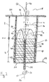
- a system for processing plasma is shown and is generally designated 10. Included in the system 10 is a plasma injector (torch) 12 that is attached or connected in fluid communication with a plasma chamber 14 wherein the plasma is processed.
- the plasma injector 12 includes a waveguide 16 which is attached directly to the plasma chamber 14, and it includes a cavity 18 which is positioned so that the waveguide 16 is located between the plasma chamber 14 and the cavity 18.
- injector 12 includes an end plate 20 which is positioned so that the cavity 18 is between the waveguide 16 and the end plate 20.
- the system 10 includes a waste source 22 that is attached to a feed line 24 which passes through the plasma injector 12. After passing through the plasma injector 12, the feed line 24 is connected in fluid communication with the plasma chamber 14.
- Fig. 1 also shows that a microwave power source 26 is connected via a line 28 with the cavity 18.
- Fig. 2 shows that the waveguide 16 is established by a hollow, substantially cylindrical-shaped wall 30 which has a length "I". As shown, one end of the wall 30 is attached to an injection port 32 on the plasma chamber 14. Further, the wall 30 surrounds an aperture 34 formed in the injection port 32 so that the waveguide 16 is in direct fluid communication with the plasma chamber 14. Importantly, the length I is dimensioned as a cut-off length so that the waveguide 16 will act to cut-off selected microwaves.
- the waveguide 16 and the cavity 18 define a longitudinal axis 36 and, as shown, both the waveguide 16 and the cavity 18 are coaxially aligned on the axis 36.
- the cavity 18 is formed by a substantially cylindrical-shaped, metal wall 38 having a length "h".
- the length "h" and the radius "a" of the cavity 18 are selected to set up a resonant microwave in the cavity 18.
- the metal wall 38 has a ceramic lining 40 which will help shield the metal wall 38 from heat losses in the cavity 18.
- the cavity 18 of the injector 12 includes a plurality of dielectric disks 42, of which the disks 42a and 42b are exemplary. More specifically, the disks 42 are formed with respective holes through which the feed line 24 may pass and may be selectively inserted into the cavity 18 to vary the length "h" and thereby maintain a resonant condition in the cavity 18.
- the disks 42 are generally flat and are oriented substantially perpendicular to the feed line 24 and, thus, also to the longitudinal axis 36. Importantly, the disks 42 fill the cavity 18 so that the cavity 18 is dielectric loaded.
- the disks 42 can be made of any suitable dielectric material and alternative embodiments for the shape of this dielectric material are possible so long as the cavity 18 is effectively dielectric loaded.
- the microwave power source 26 is activated to set up a resonant microwave (not shown) in the cavity 18.
- the resonant microwave is established to generate an electric field 44 which will penetrate into the waveguide 16.
- this electric field 44 is azimuthal (E ⁇ ) and is a transverse electric field of the type which is commonly referred to by skilled artisans as the TE mode. More specifically, by referring to Fig. 2 it can be seen that for the TE mode of the electric field 44, the maximum field strength is achieved at a radius which extends to approximately midway between the longitudinal axis 36 and the wall 30 of the waveguide 16.
- the TE mode electric field 44 should also have its minimum strength both at the wall 30 and at the longitudinal axis 36.
- the TE mode electric field 44 is configured in the waveguide 16 to define both a central region 46 and an outer region 48.
- the outer region 48 is located between the wall 30 of waveguide 16 and the electric field 44, while the central region 46 surrounds and extends along the longitudinal axis 36.
- An important consequence of the TE mode electrical field 44 is that the central region 46 is distanced from the wall 30 of the waveguide 16.
- waste 50 is introduced into the waveguide 16 via the feed line 24.
- the waste 50 may be refractive materials and may be either in a solid or a liquid state.
- a gaseous vapor such as sodium vapor 52, can be introduced through the feed line 24 either by itself or together with waste 50, as desired.
- only the more volatile sodium vapor 52 is initially introduced through the feed line 24 and into the waveguide 16. This is done for the purpose of initiating the ionization process.
- Once there has been an initial ionization of the sodium vapor 52 there is a basis for generating the very high temperatures (>3000K) that are required for subsequent ionization of the waste 50 that will create the plasma discharge 54.
- An important aspect of the present invention is that due to the configuration of the TE electric field 44, the ionization of both the sodium vapor 52 and the waste 50 will occur primarily in the central region 46. Thus, the high heat loads that accompany this ionization will be distanced from the wall 30. Further, the central region 46 provides for stability of the plasma discharge 54 in that it will help prevent the plasma discharge 54 from wandering off axis.
- the tuning of cavity 18 to set up a resonant microwave can be accomplished in several ways. For one, the length "h" of cavity 18 can be varied. To do this, additional disks 42 can be added to the dielectric load of the cavity 18. Also, water (not shown) can be added to the waste 50 and sodium vapor 52 as required. In these ways, as with others known in the pertinent art, the cavity 18 can be tuned so that the resonant microwave that is established in the cavity 18 will establish the appropriate TE mode electrical field 44 in the waveguide 16.
- the waveguide 16 establish a cut-off wavelength in order to prevent the propagation of microwaves into the plasma chamber 14. Accordingly, the microwave source 26 needs to be adjusted in a manner which will reconcile the resonant microwave in the cavity 18, the TE mode electrical field 44 in the waveguide 16 and the cut-off wavelength for microwaves confined to the waveguide 16.
Landscapes
- Physics & Mathematics (AREA)
- Engineering & Computer Science (AREA)
- Plasma & Fusion (AREA)
- Electromagnetism (AREA)
- Spectroscopy & Molecular Physics (AREA)
- Physical Or Chemical Processes And Apparatus (AREA)
- Plasma Technology (AREA)
- Chemical Vapour Deposition (AREA)
Applications Claiming Priority (2)
| Application Number | Priority Date | Filing Date | Title |
|---|---|---|---|
| US09/440,358 US6303007B1 (en) | 1999-11-15 | 1999-11-15 | Plasma injector |
| US440358 | 1999-11-15 |
Publications (2)
| Publication Number | Publication Date |
|---|---|
| EP1102521A2 true EP1102521A2 (fr) | 2001-05-23 |
| EP1102521A3 EP1102521A3 (fr) | 2003-04-16 |
Family
ID=23748445
Family Applications (1)
| Application Number | Title | Priority Date | Filing Date |
|---|---|---|---|
| EP00308040A Withdrawn EP1102521A3 (fr) | 1999-11-15 | 2000-09-15 | Injecteur à plasma |
Country Status (3)
| Country | Link |
|---|---|
| US (1) | US6303007B1 (fr) |
| EP (1) | EP1102521A3 (fr) |
| JP (1) | JP3738181B2 (fr) |
Cited By (2)
| Publication number | Priority date | Publication date | Assignee | Title |
|---|---|---|---|---|
| EP1745683A2 (fr) * | 2004-04-19 | 2007-01-24 | Plasma'05 Alkalmazástechnikai Kutató-Fejleszto Kft | Nouveau pistolet a plasma et son application dans des methodes de conversion de matiere |
| US9831066B1 (en) | 2016-05-27 | 2017-11-28 | Mks Instruments, Inc. | Compact microwave plasma applicator utilizing conjoining electric fields |
Families Citing this family (10)
| Publication number | Priority date | Publication date | Assignee | Title |
|---|---|---|---|---|
| AUPQ861500A0 (en) * | 2000-07-06 | 2000-08-03 | Varian Australia Pty Ltd | Plasma source for spectrometry |
| US6730231B2 (en) | 2002-04-02 | 2004-05-04 | Archimedes Technology Group, Inc. | Plasma mass filter with axially opposed plasma injectors |
| FR2864795B1 (fr) * | 2004-01-06 | 2008-04-18 | Air Liquide | Procede de traitement des gaz par des decharges hautes frequence |
| US20050172896A1 (en) * | 2004-02-10 | 2005-08-11 | Tihiro Ohkawa | Injector for plasma mass filter |
| US20060233968A1 (en) * | 2005-04-19 | 2006-10-19 | Tihiro Ohkawa | System and method for vaporizing a metal |
| US20060261522A1 (en) * | 2005-05-18 | 2006-11-23 | Tihiro Ohkawa | System and method for vaporizing a solid material |
| US7831008B2 (en) * | 2005-10-21 | 2010-11-09 | General Atomics | Microwave-powered pellet accelerator |
| US20070092050A1 (en) * | 2005-10-21 | 2007-04-26 | Parks Paul B | Microwave-powered pellet accelerator |
| CN104520453A (zh) | 2011-11-10 | 2015-04-15 | 先进磁工艺股份有限公司 | 用于分离的磁电-等离子体分离器及方法 |
| CN102869182A (zh) * | 2012-09-12 | 2013-01-09 | 清华大学 | 一种基于耦合窗辐射的大体积微波等离子体发生装置 |
Family Cites Families (13)
| Publication number | Priority date | Publication date | Assignee | Title |
|---|---|---|---|---|
| SE338962B (fr) | 1970-06-04 | 1971-09-27 | B Lehnert | |
| DE2964778D1 (en) * | 1978-04-12 | 1983-03-24 | New Japan Radio Co Ltd | Microwave melting device |
| US4987007A (en) | 1988-04-18 | 1991-01-22 | Board Of Regents, The University Of Texas System | Method and apparatus for producing a layer of material from a laser ion source |
| US5250773A (en) * | 1991-03-11 | 1993-10-05 | Mcdonnell Douglas Corporation | Microwave heating device |
| US5468356A (en) * | 1991-08-23 | 1995-11-21 | The United States Of America As Represented By The Secretary Of The Navy | Large scale purification of contaminated air |
| US5361016A (en) | 1992-03-26 | 1994-11-01 | General Atomics | High density plasma formation using whistler mode excitation in a reduced cross-sectional area formation tube |
| US5225740A (en) | 1992-03-26 | 1993-07-06 | General Atomics | Method and apparatus for producing high density plasma using whistler mode excitation |
| US5324485A (en) * | 1992-08-12 | 1994-06-28 | Martin Marietta Energy Systems, Inc. | Microwave applicator for in-drum processing of radioactive waste slurry |
| US5350454A (en) | 1993-02-26 | 1994-09-27 | General Atomics | Plasma processing apparatus for controlling plasma constituents using neutral and plasma sound waves |
| US5681434A (en) | 1996-03-07 | 1997-10-28 | Eastlund; Bernard John | Method and apparatus for ionizing all the elements in a complex substance such as radioactive waste and separating some of the elements from the other elements |
| GB9704077D0 (en) | 1996-03-15 | 1997-04-16 | British Nuclear Fuels Plc | Improvements in and relating to processing |
| US5830328A (en) * | 1996-06-24 | 1998-11-03 | The United States Of America As Represented By The Secretary Of The Navy | Contamination control of emission discharge |
| US5977528A (en) * | 1997-10-10 | 1999-11-02 | Eet Corporation | Rectangular microwave applicator and waste treatment method |
-
1999
- 1999-11-15 US US09/440,358 patent/US6303007B1/en not_active Expired - Fee Related
-
2000
- 2000-09-15 EP EP00308040A patent/EP1102521A3/fr not_active Withdrawn
- 2000-10-16 JP JP2000314897A patent/JP3738181B2/ja not_active Expired - Fee Related
Cited By (7)
| Publication number | Priority date | Publication date | Assignee | Title |
|---|---|---|---|---|
| EP1745683A2 (fr) * | 2004-04-19 | 2007-01-24 | Plasma'05 Alkalmazástechnikai Kutató-Fejleszto Kft | Nouveau pistolet a plasma et son application dans des methodes de conversion de matiere |
| US9831066B1 (en) | 2016-05-27 | 2017-11-28 | Mks Instruments, Inc. | Compact microwave plasma applicator utilizing conjoining electric fields |
| WO2017205034A3 (fr) * | 2016-05-27 | 2018-07-26 | Mks Instruments, Inc. | Applicateur compact de plasma par micro-ondes mettant en œuvre des champs électriques conjugués |
| CN109155229A (zh) * | 2016-05-27 | 2019-01-04 | Mks 仪器公司 | 利用结合电场的紧凑型微波等离子体施加器 |
| KR20190002529A (ko) * | 2016-05-27 | 2019-01-08 | 엠케이에스 인스트루먼츠, 인코포레이티드 | 결합 전기장을 이용한 소형 마이크로파 플라즈마 어플리케이터 |
| CN109155229B (zh) * | 2016-05-27 | 2020-07-10 | Mks 仪器公司 | 利用结合电场的紧凑型微波等离子体施加器 |
| KR102378924B1 (ko) | 2016-05-27 | 2022-03-28 | 엠케이에스 인스트루먼츠, 인코포레이티드 | 결합 전기장을 이용한 소형 마이크로파 플라즈마 어플리케이터 |
Also Published As
| Publication number | Publication date |
|---|---|
| US6303007B1 (en) | 2001-10-16 |
| JP3738181B2 (ja) | 2006-01-25 |
| JP2001176695A (ja) | 2001-06-29 |
| EP1102521A3 (fr) | 2003-04-16 |
Similar Documents
| Publication | Publication Date | Title |
|---|---|---|
| US4952273A (en) | Plasma generation in electron cyclotron resonance | |
| US4727293A (en) | Plasma generating apparatus using magnets and method | |
| US5389153A (en) | Plasma processing system using surface wave plasma generating apparatus and method | |
| US6812647B2 (en) | Plasma generator useful for ion beam generation | |
| KR100291152B1 (ko) | 플라즈마발생장치 | |
| KR100358902B1 (ko) | 마이크로파를이용한플라스마생성장치 | |
| JP4671313B2 (ja) | 同軸マイクロ波アプリケータを備えた電子サイクロトロン共振プラズマ源およびプラズマ生成方法 | |
| JP6568050B2 (ja) | 誘電体共振器を使用するマイクロ波プラズマ分光計 | |
| US5517085A (en) | Apparatus including ring-shaped resonators for producing microwave plasmas | |
| US5361016A (en) | High density plasma formation using whistler mode excitation in a reduced cross-sectional area formation tube | |
| US4877509A (en) | Semiconductor wafer treating apparatus utilizing a plasma | |
| US6303007B1 (en) | Plasma injector | |
| WO1998001599A9 (fr) | Applicateur hyperfrequence destine a une source de plasma a resonance par cyclotron electronique | |
| US6261525B1 (en) | Process gas decomposition reactor | |
| JP2004502958A (ja) | プラズマ発生方法、分光測定用プラズマ源および導波路 | |
| US6734385B1 (en) | Microwave plasma burner | |
| JP2002500429A (ja) | Ecrプラズマ源用の同軸共鳴マルチポートマイクロ波アプリケータ | |
| Kaeppelin et al. | Different operational regimes in a helicon plasma source | |
| CN112424901B (zh) | 用于回旋加速器的低腐蚀内部离子源 | |
| Liu et al. | Design aspects of a compact, single-frequency, permanent-magnet electron cyclotron resonance ion source with a large uniformly distributed resonant plasma volume | |
| Geddes et al. | Enhanced dissociation of molecular nitrogen in a microwave plasma with an applied magnetic field | |
| Keller | High-intensity ion sources for accelerators with emphasis on H− beam formation and transport | |
| KR20030064125A (ko) | 고효율 상압 마이크로웨이브 플라즈마시스템 | |
| JPH0935651A (ja) | イオン源 | |
| JPH0653173A (ja) | プラズマ加熱機構を有するプラズマ処理装置 |
Legal Events
| Date | Code | Title | Description |
|---|---|---|---|
| PUAI | Public reference made under article 153(3) epc to a published international application that has entered the european phase |
Free format text: ORIGINAL CODE: 0009012 |
|
| AK | Designated contracting states |
Kind code of ref document: A2 Designated state(s): AT BE CH CY DE DK ES FI FR GB GR IE IT LI LU MC NL PT SE |
|
| AX | Request for extension of the european patent |
Free format text: AL;LT;LV;MK;RO;SI |
|
| PUAL | Search report despatched |
Free format text: ORIGINAL CODE: 0009013 |
|
| AK | Designated contracting states |
Designated state(s): AT BE CH CY DE DK ES FI FR GB GR IE IT LI LU MC NL PT SE |
|
| AX | Request for extension of the european patent |
Extension state: AL LT LV MK RO SI |
|
| RIC1 | Information provided on ipc code assigned before grant |
Ipc: 7H 05B 6/80 B Ipc: 7H 05H 1/24 A |
|
| 17P | Request for examination filed |
Effective date: 20030718 |
|
| AKX | Designation fees paid |
Designated state(s): DE FR GB |
|
| RAP1 | Party data changed (applicant data changed or rights of an application transferred) |
Owner name: ARCHIMEDES OPERATING, LLC |
|
| STAA | Information on the status of an ep patent application or granted ep patent |
Free format text: STATUS: THE APPLICATION HAS BEEN WITHDRAWN |
|
| 18W | Application withdrawn |
Effective date: 20060515 |