EP1102609B1 - Applicateur de champ magnetique pour le chauffage de substances ou de corps solides magnetiques ou magnetisables dans des tissus biologiques - Google Patents
Applicateur de champ magnetique pour le chauffage de substances ou de corps solides magnetiques ou magnetisables dans des tissus biologiques Download PDFInfo
- Publication number
- EP1102609B1 EP1102609B1 EP00956196A EP00956196A EP1102609B1 EP 1102609 B1 EP1102609 B1 EP 1102609B1 EP 00956196 A EP00956196 A EP 00956196A EP 00956196 A EP00956196 A EP 00956196A EP 1102609 B1 EP1102609 B1 EP 1102609B1
- Authority
- EP
- European Patent Office
- Prior art keywords
- magnetic
- magnetic field
- yoke
- applicator according
- field applicator
- Prior art date
- Legal status (The legal status is an assumption and is not a legal conclusion. Google has not performed a legal analysis and makes no representation as to the accuracy of the status listed.)
- Expired - Lifetime
Links
- 230000005291 magnetic effect Effects 0.000 title claims abstract description 145
- 239000000126 substance Substances 0.000 title claims abstract description 9
- 238000010438 heat treatment Methods 0.000 title claims description 11
- 239000007787 solid Substances 0.000 title claims description 6
- 229910000859 α-Fe Inorganic materials 0.000 claims abstract description 48
- 238000004804 winding Methods 0.000 claims abstract 3
- 206010028980 Neoplasm Diseases 0.000 claims description 24
- 238000001816 cooling Methods 0.000 claims description 23
- 230000007704 transition Effects 0.000 claims description 12
- 238000004519 manufacturing process Methods 0.000 claims description 5
- RYGMFSIKBFXOCR-UHFFFAOYSA-N Copper Chemical compound [Cu] RYGMFSIKBFXOCR-UHFFFAOYSA-N 0.000 claims description 3
- 229910052802 copper Inorganic materials 0.000 claims description 3
- 239000010949 copper Substances 0.000 claims description 3
- 239000011553 magnetic fluid Substances 0.000 claims description 3
- 230000002093 peripheral effect Effects 0.000 claims description 3
- 238000004026 adhesive bonding Methods 0.000 claims description 2
- 239000002105 nanoparticle Substances 0.000 claims description 2
- 238000005245 sintering Methods 0.000 claims 1
- 206010020843 Hyperthermia Diseases 0.000 abstract description 24
- 230000036031 hyperthermia Effects 0.000 abstract description 24
- 238000000034 method Methods 0.000 abstract description 15
- 238000002679 ablation Methods 0.000 abstract description 5
- 230000004907 flux Effects 0.000 description 14
- 210000001519 tissue Anatomy 0.000 description 12
- 238000009413 insulation Methods 0.000 description 6
- 239000007788 liquid Substances 0.000 description 6
- 238000002560 therapeutic procedure Methods 0.000 description 5
- 239000000463 material Substances 0.000 description 4
- 238000011282 treatment Methods 0.000 description 4
- 238000003491 array Methods 0.000 description 3
- 210000000746 body region Anatomy 0.000 description 3
- 210000004027 cell Anatomy 0.000 description 3
- 230000008859 change Effects 0.000 description 3
- 238000002512 chemotherapy Methods 0.000 description 3
- 230000006378 damage Effects 0.000 description 3
- 238000013461 design Methods 0.000 description 3
- 230000002349 favourable effect Effects 0.000 description 3
- 239000007943 implant Substances 0.000 description 3
- 230000005855 radiation Effects 0.000 description 3
- 238000001959 radiotherapy Methods 0.000 description 3
- 230000001225 therapeutic effect Effects 0.000 description 3
- 238000010521 absorption reaction Methods 0.000 description 2
- 230000008901 benefit Effects 0.000 description 2
- 230000015572 biosynthetic process Effects 0.000 description 2
- 201000011510 cancer Diseases 0.000 description 2
- 239000003990 capacitor Substances 0.000 description 2
- 239000002872 contrast media Substances 0.000 description 2
- 230000000694 effects Effects 0.000 description 2
- 230000005684 electric field Effects 0.000 description 2
- 230000017525 heat dissipation Effects 0.000 description 2
- 238000002513 implantation Methods 0.000 description 2
- 238000003780 insertion Methods 0.000 description 2
- 230000037431 insertion Effects 0.000 description 2
- 230000004807 localization Effects 0.000 description 2
- 239000003094 microcapsule Substances 0.000 description 2
- 239000003921 oil Substances 0.000 description 2
- 238000011275 oncology therapy Methods 0.000 description 2
- 230000009467 reduction Effects 0.000 description 2
- 238000001356 surgical procedure Methods 0.000 description 2
- 210000004881 tumor cell Anatomy 0.000 description 2
- 238000010792 warming Methods 0.000 description 2
- 206010051779 Bone marrow toxicity Diseases 0.000 description 1
- 206010021143 Hypoxia Diseases 0.000 description 1
- 206010027476 Metastases Diseases 0.000 description 1
- 206010060862 Prostate cancer Diseases 0.000 description 1
- 208000000236 Prostatic Neoplasms Diseases 0.000 description 1
- 230000004913 activation Effects 0.000 description 1
- 230000001154 acute effect Effects 0.000 description 1
- 239000000853 adhesive Substances 0.000 description 1
- 230000001070 adhesive effect Effects 0.000 description 1
- 230000017531 blood circulation Effects 0.000 description 1
- 238000007664 blowing Methods 0.000 description 1
- 210000001124 body fluid Anatomy 0.000 description 1
- 239000010839 body fluid Substances 0.000 description 1
- 231100000366 bone marrow toxicity Toxicity 0.000 description 1
- 238000003763 carbonization Methods 0.000 description 1
- 230000015556 catabolic process Effects 0.000 description 1
- 239000003795 chemical substances by application Substances 0.000 description 1
- 230000000973 chemotherapeutic effect Effects 0.000 description 1
- 230000015271 coagulation Effects 0.000 description 1
- 238000005345 coagulation Methods 0.000 description 1
- 239000002131 composite material Substances 0.000 description 1
- 238000010276 construction Methods 0.000 description 1
- 238000011161 development Methods 0.000 description 1
- 230000018109 developmental process Effects 0.000 description 1
- 238000009826 distribution Methods 0.000 description 1
- 238000010292 electrical insulation Methods 0.000 description 1
- 230000004795 endocrine process Effects 0.000 description 1
- 238000005516 engineering process Methods 0.000 description 1
- 230000005284 excitation Effects 0.000 description 1
- 230000005294 ferromagnetic effect Effects 0.000 description 1
- 230000002977 hyperthermial effect Effects 0.000 description 1
- 238000003384 imaging method Methods 0.000 description 1
- 230000001976 improved effect Effects 0.000 description 1
- 230000006872 improvement Effects 0.000 description 1
- 230000001939 inductive effect Effects 0.000 description 1
- 230000002757 inflammatory effect Effects 0.000 description 1
- 238000009434 installation Methods 0.000 description 1
- 230000002427 irreversible effect Effects 0.000 description 1
- 239000003446 ligand Substances 0.000 description 1
- 239000002122 magnetic nanoparticle Substances 0.000 description 1
- 230000007246 mechanism Effects 0.000 description 1
- 230000004060 metabolic process Effects 0.000 description 1
- 230000009401 metastasis Effects 0.000 description 1
- 230000017074 necrotic cell death Effects 0.000 description 1
- 238000005457 optimization Methods 0.000 description 1
- 238000013021 overheating Methods 0.000 description 1
- 230000016087 ovulation Effects 0.000 description 1
- 238000005192 partition Methods 0.000 description 1
- 230000035515 penetration Effects 0.000 description 1
- 230000035699 permeability Effects 0.000 description 1
- 230000004962 physiological condition Effects 0.000 description 1
- 230000035790 physiological processes and functions Effects 0.000 description 1
- 230000008569 process Effects 0.000 description 1
- 108090000623 proteins and genes Proteins 0.000 description 1
- 238000011084 recovery Methods 0.000 description 1
- 230000008929 regeneration Effects 0.000 description 1
- 238000011069 regeneration method Methods 0.000 description 1
- 238000007789 sealing Methods 0.000 description 1
- 230000011664 signaling Effects 0.000 description 1
- 230000000638 stimulation Effects 0.000 description 1
- 230000008093 supporting effect Effects 0.000 description 1
- 238000011477 surgical intervention Methods 0.000 description 1
- 230000004083 survival effect Effects 0.000 description 1
- 230000009885 systemic effect Effects 0.000 description 1
- 239000003053 toxin Substances 0.000 description 1
- 231100000765 toxin Toxicity 0.000 description 1
- 108700012359 toxins Proteins 0.000 description 1
- 238000012546 transfer Methods 0.000 description 1
- 230000004614 tumor growth Effects 0.000 description 1
- 238000002604 ultrasonography Methods 0.000 description 1
Images


Classifications
-
- A—HUMAN NECESSITIES
- A61—MEDICAL OR VETERINARY SCIENCE; HYGIENE
- A61N—ELECTROTHERAPY; MAGNETOTHERAPY; RADIATION THERAPY; ULTRASOUND THERAPY
- A61N2/00—Magnetotherapy
- A61N2/02—Magnetotherapy using magnetic fields produced by coils, including single turn loops or electromagnets
-
- A—HUMAN NECESSITIES
- A61—MEDICAL OR VETERINARY SCIENCE; HYGIENE
- A61N—ELECTROTHERAPY; MAGNETOTHERAPY; RADIATION THERAPY; ULTRASOUND THERAPY
- A61N1/00—Electrotherapy; Circuits therefor
- A61N1/40—Applying electric fields by inductive or capacitive coupling ; Applying radio-frequency signals
- A61N1/403—Applying electric fields by inductive or capacitive coupling ; Applying radio-frequency signals for thermotherapy, e.g. hyperthermia
- A61N1/406—Applying electric fields by inductive or capacitive coupling ; Applying radio-frequency signals for thermotherapy, e.g. hyperthermia using implantable thermoseeds or injected particles for localized hyperthermia
-
- H—ELECTRICITY
- H01—ELECTRIC ELEMENTS
- H01F—MAGNETS; INDUCTANCES; TRANSFORMERS; SELECTION OF MATERIALS FOR THEIR MAGNETIC PROPERTIES
- H01F3/00—Cores, Yokes, or armatures
- H01F3/02—Cores, Yokes, or armatures made from sheets
-
- B—PERFORMING OPERATIONS; TRANSPORTING
- B82—NANOTECHNOLOGY
- B82Y—SPECIFIC USES OR APPLICATIONS OF NANOSTRUCTURES; MEASUREMENT OR ANALYSIS OF NANOSTRUCTURES; MANUFACTURE OR TREATMENT OF NANOSTRUCTURES
- B82Y5/00—Nanobiotechnology or nanomedicine, e.g. protein engineering or drug delivery
-
- Y—GENERAL TAGGING OF NEW TECHNOLOGICAL DEVELOPMENTS; GENERAL TAGGING OF CROSS-SECTIONAL TECHNOLOGIES SPANNING OVER SEVERAL SECTIONS OF THE IPC; TECHNICAL SUBJECTS COVERED BY FORMER USPC CROSS-REFERENCE ART COLLECTIONS [XRACs] AND DIGESTS
- Y10—TECHNICAL SUBJECTS COVERED BY FORMER USPC
- Y10S—TECHNICAL SUBJECTS COVERED BY FORMER USPC CROSS-REFERENCE ART COLLECTIONS [XRACs] AND DIGESTS
- Y10S977/00—Nanotechnology
- Y10S977/902—Specified use of nanostructure
- Y10S977/932—Specified use of nanostructure for electronic or optoelectronic application
- Y10S977/949—Radiation emitter using nanostructure
- Y10S977/95—Electromagnetic energy
Definitions
- the invention relates to a magnetic field applicator for heating magnetic or magnetizable substances or solids in biological Tissue according to the preamble of claim 1.
- Cancers are generally known by surgical means Removal, chemotherapy, radiation therapy, or Combination of these methods is treated. Each of these methods is subject to certain Limitations: Surgical removal of the tumor is special in advanced stages, after metastasis, when the tumor is in Neighborhood to critical areas of the body or diffuse tumor growth imprecise localization is not possible or offers little chance of recovery. That is why the surgical intervention is generally combined with Radiotherapy and chemotherapy. The former can only be as accurate as that Localization of the tumor by means of imaging procedures with the greatest possible extent Recessing or protecting the healthy tissue. chemotherapeutic By contrast, agents have a systemic effect. H. on the whole body. Here is in the Rule limiting the bone marrow toxicity or the non-specificity of the therapy. Therefore, undesirable side effects are common to all of these therapy methods according to the state of the art inevitable and damage in the Usually also healthy tissue.
- Hyperthermia has become an additional modality in recent years gained importance in which the tumor tissue to temperatures above 41 ° C is heated and so in combination with surgery, radiation therapy and chemotherapy the success of treatment, d. H. local control, e.g. T. even Survival, can be improved.
- the body supports it in a controlled and rather slow manner Breakdown of tumor tissue. This process is called hyperthermia, while at higher temperatures from 47 ° C an acute cell destruction depending on the temperature as necrosis, coagulation or carbonization takes place and is therefore called thermal ablation.
- Hyperthermia systems after the prior art are either only for hyperthermia mentioned above or only suitable for thermal ablation.
- hyperthermia in general is that usually no precisely localizable and above all homogeneous heating of a target region of the body is possible according to the state of the art. Under certain physiological Conditions (e.g. oxygen deficiency, low pH) in the Tumor cancer cells are more sensitive to hyperthermia, however this only applies in a few cases. Hyperthermia per se is not effective at Tumor cells compared to normal tissue. That is why the limitation of Warming up to the medically indicated region (which is not necessarily only to the Tumor must be limited) of particular importance and after State of the art not realized.
- physiological Conditions e.g. oxygen deficiency, low pH
- E-field dominant systems are used the electromagnetic waves usually in the megahertz range of dipole antennas or other antenna designs or antenna arrays, used for regional or local hyperthermia.
- Common difficulty of all of these E-fields dominant systems is that the power absorption is only through the elaborate Control of the electric field can be achieved and that the warming depends on the electrical conductivity of the respective target tissue, which is naturally very heterogeneous, which results in uneven heating even with homogeneous radiation from the E-field.
- thermoseeds are introduced in the tumor area, those made of magnetic, in particular ferromagnetic or made of magnetizable Exist or contain material. These thermoseeds have a typical size of several centimeters in length and one Diameter in the millimeter range. Obviously, such thermoseeds are required to implant surgically in a complex manner. These thermoseeds are generated during treatment with a patient outside of a patient Magnetic alternating field applied, whereby by known Hysteresis effects Heat arises in the thermoseeds as hyperthermia.
- Such seeds are heated according to the principle of "hot springs", i.e. H.
- H hot springs
- the temperatures drop around the seed exponentially, so in clinical Application the distance between the seeds must not be greater than 1 cm. With larger or uneven distances there is a thermal underdosing, which can also prevent therapy success. Especially with Larger tumors thus need very tight implantation the seeds, making the method surgically complex and patient-friendly is stressful.
- the seeds also for optimal power consumption parallel to the alternating magnetic field be aligned. Overheating is caused by the so-called Curie temperature Prevents self-regulating thermoseeds at which after reaching the Curie temperature the ferrite into a non-magnetizable state passes over and then no further power consumption takes place.
- thermoseeds As a magnetic field applicator for the alternating magnetic field of a resonant circuit, the body region in its axis area a patient can be inserted with the implanted thermoseeds. Concrete air coils are used here, in the middle areas of a patient treatment sits on a non-magnetizable support plate.
- thermoseeds The disadvantage of interstitial hyperthermia with thermoseeds is the high one surgical effort and the high invasiveness of the method, the risk of not exact alignment or position change of the seeds and with that associated risk of thermal underdosing and a limitation of Small-scale tumor method.
- the Magnetic field applicator comprises a magnetic yoke, each with two opposite, pole shoes spaced apart by an exposure gap and two magnet coils assigned to each of these pole pieces. Specifically, it is rectangular Magnetic yoke shown, starting from the center of each yoke leg a pole piece is aimed at the center of the rectangle, thereby an exposure area is formed there. There are solenoids on the pole pieces attached, each opposite to each other and with an associated Capacitor arrangement are connected to an oscillating circuit.
- the object of the invention is therefore a magnetic field applicator for heating of magnetic or magnetizable substances or solids in to create biological tissue that meets the above requirements regarding a series solution for hospital operation or another, possibly industrial use.
- the magnetic yoke and the pole shoes consist of composite and assembled ferrite components.
- the solenoids are disc coils with at least one helical Turn, which are each assigned to a pole piece and the respective pole piece end with a circumferential magnetic coil / pole shoe gap in between include.
- Ferrites are ceramic-like building blocks that cannot be found in any shape allow reasonable effort to be made, especially not in the overall form of the magnetic yoke used here. It is therefore proposed according to the invention assemble the magnetic yoke from ferrite building blocks, whereby at the transition points disruption of a flow as even as possible may occur. Advantageous solutions to master these problems are given below.
- the magnetic field applicator according to the invention is equally suitable for the implementation of hyperthermia as well as for thermal ablation procedures.
- the magnetic field applicator according to the invention is also suitable for heating other substances or solids for medical purposes Applications outside of cancer therapy. Under the latter are all heat-related medical applications understood such.
- the solenoids should have one or more turns that are helical and be made of stranded copper stranded wire to avoid eddy current losses to keep it as small as possible.
- the pole pieces according to claim 3 cylindrical or circular in a plan view, with opposing, parallel aligned pole shoe circular surfaces in Distance between the exposure slits.
- The are accordingly Magnetic coils formed in a ring. This leads to an equalization of magnetic flux with a reduction in heating that otherwise would occur at spatial corners and edges increased.
- the conditions are particularly favorable in terms of energy and flow technology according to claim 4, if the disc-shaped magnet coil as close as possible to The exposure slit is arranged, in particular in a flush arrangement with regard to the respectively assigned pole shoe end surface.
- Another optimization is achieved if the solenoid / pole shoe gap in one Size of about 1/10 of the pole piece diameter (0.07 to 0.1 times) and the peripheral edge of the respective pole shoe end surface is rounded. In order to harmful increases in flux density are greatly reduced.
- the pole piece diameter should be larger than the exposure gap width his. Stray fields outside the pole shoes or of the ovulation volume, which reduces the flux density in the ferrite components and thus the losses in the ferrite material are kept relatively small can. In the case of pole pieces with a relatively small cross section, these losses would occur increase disproportionately in the ferrite building blocks.
- the magnetic yoke is made of cuboid ferrite components composed of their surfaces to create smooth transitions are ground plane-parallel, possibly removing outer sinter layers.
- the round pole pieces are made of wedge-shaped ferrite blocks as composed of pieces of cake, with neighboring areas are ground plane-parallel.
- the wedge-shaped ferrite blocks for formation made of pole pieces, leaving a tubular central recess open is introduced through the cooling air.
- the ferrite plates is preferably a temperature-resistant, two-component adhesive used.
- the gaps between the ferrite plates serve both for electrical insulation as well as the cooling by blowing cooling air through the column.
- the Cooling is necessary because, despite the low conductivity of the ferrites, they are relatively large Eddy currents arise and the heat generated is dissipated got to. Liquid cooling would be more effective, but is because of the insulation requirements not feasible. Oil cooling is because of the flammability of oils associated with dangers and comparable non-flammable liquids regularly contain toxins. General would be with liquid cooling the sealing problem in particular with a movable yoke part in Connection with the other technical difficulties only with great effort solvable.
- the magnetic yoke from at least one vertical yoke part and two connected to it Cross-yoke parts, with the cross-yoke parts facing each other Pole shoes are connected.
- At least one transverse yoke part is relatively opposite the other cross-yoke part to change the exposure gap adjustable.
- the exposed volume should be kept as small as possible. This can be achieved with the displaceable cross yoke part design that for easy insertion, e.g. B. a patient in the exposure gap the pole shoe distance is increased by shifting at least one transverse yoke part and then reduced again as much as possible for the exposure becomes.
- the magnetic yoke can be designed as a C-arm in which the area of the C opening is that formed by the pole pieces Represents exposure gap.
- the good accessibility of the pole shoes is advantageous here and the magnetic coils and thus the entire exposure gap. Indeed Relatively large stray fields occur with a C-arm and for the Magnetic inference of flow paths of different lengths and diversion problems at the corners.
- a transverse yoke part with an associated magnet coil is relative as a structural unit on the other hand, the cross-yoke part is adjustable to adjust the exposure gap executed. Magnetic inference on both sides is advantageous here divided into two equally long paths that have the same geometry.
- the mechanism for the relative position of at least one transverse yoke part is opposite a C-magnet yoke easier to implement because the vertical yoke parts as supports on both sides can be used.
- a structural unit from a lower transverse yoke part and attached to the associated pole piece with magnetic coil On This stationary pole piece can then be used, for example, by a patient sledge with patient bed and slide position indicator made of plastic material attached the patient with a setting of the exposure gap no longer has to be moved. Opposite this fixed unit is then a portal from the two vertical yoke parts from the upper one Transverse yoke part with the associated pole piece with magnetic coil by means of a Vertical adjustment device for setting the exposure gap width adjustable.
- a vertical adjustment device can according to claim 15 as a simple linear drive are carried out, each preferably on a vertical magnetic yoke part attacks.
- a self-locking spindle drive are used, whereby the overall arrangement can be carried out very safely without the risk of heavy magnetic yoke components due to errors in the adjustment device endanger a patient.
- the magnetic yoke in be held in a supporting structure in which cooling air can also be supplied and conducted which is then the cooling air gap of the ferrite modules for heat dissipation flows through.
- the exposure gap and thus the exposure volume to the side be limited by field delimiting coils and / or by bulkheads.
- the magnetic field applicator according to the invention can be used for one localized and non-contact hyperthermia in all possible fields Using tissues, bodies, objects and masses introduced magnetic and / or magnetizable substances to suitable Be used for purposes.
- a preferred application of the magnetic field applicator is in the medical field, in particular in cancer therapy, preferably a magnetizable substance Liquid with magnetizable nanoparticles is used.
- a magnetizable substance Liquid with magnetizable nanoparticles is used.
- the tumor area should thus be locally heatable to temperature values above approx. 41 ° C his.
- alternating magnetic fields with magnetic field strengths from approx. 10 to 15 kA / m and frequencies from approx. 50 to 100 kHz.
- the required temperatures for tumor therapy are reached.
- temperatures can also be used be suitable in a further frequency range from 20 to 500 kHz.
- FIG. 1 schematically shows a magnetic field applicator 1 for hyperthermia shown in which a body to be fielded, in which a magnetic or magnetizable substance or solid can be introduced, can be irradiated.
- a tumor area in one is particularly suitable human body in which a liquid with z.
- B. magnetic nanoparticles is introduced the tumor area preferably at temperature values can be heated above about 41 ° C.
- the magnetic field applicator 1 comprises a magnetic yoke 2 which is in an M-shape Three-leg arrangement is formed and two spaced, parallel Vertical yoke parts 3, 4 and two transverse yoke parts 5 connected between them 6 has.
- a unit from the lower transverse yoke part 6 and associated lower Pole shoe 8 with lower magnet coil 10 is fixed in place.
- a portal from the two vertical yoke parts 3, 4, the connected upper transverse yoke part 5 and this associated upper pole shoe 7 with upper Magnetic coil 9 by means of a self-locking spindle drive 11 for setting the exposure gap of the exposure slit 12 can be adjusted.
- the 1 can further be seen that the exposure gap 12 through Partition walls 14, 15 is delimited, which delimit an insertion space 13.
- the Bulkheads 14, 15 can be vertically adjustable relative to each other.
- the upper magnet coil 9 and the lower magnetic coil 10 are designed as disc coils one or more turns, which are helical and stranded Copper stranded wires are made.
- the magnet coils 9, 10 are the pole shoe ends with a magnetic coil / pole shoe gap in between and rotating (a) include.
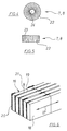
- FIG. 4 which shows a plan view of one of the pole pieces 7, 8, the pole pieces are 7, 8 formed circular.
- the magnet coil / pole shoe gap (a) lies in a size range from 0.07 to 0.1 times the pole piece diameter (d), the magnetic coil being arranged approximately flush with the pole shoe end face and the circumferential edge on the pole shoe end surface is rounded is.
- pole piece diameter (d) Size of the exposure gap 12 designed to reduce the stray fields. So is in a preferred embodiment to avoid stray fields the pole piece diameter (d) is larger than the exposure gap 12.
- each a side view or show a plan view of the magnetic yoke 2 the magnetic yoke 2 is off cuboid ferrite building blocks 16 composed, the surfaces of Sintered layers are freed and ground parallel to each other.
- These cuboid Ferrite building blocks 16 are again, as can be seen from FIG. 6 is, strung together, in the magnetic yoke 2 along the direction of magnetic flux 17 aligned ferrite plates 18 built.
- These ferrite plates 18 are transverse to the magnetic flux direction 17 through insulation / cooling gaps 19 separated from each other.
- plastic separators 20 are inserted in side areas, wherein the ferrite plates 18 via these plastic separators 20 to the cuboid Ferrite blocks 16 are glued as yoke elements.
- Through the insulation / cooling column 19 can be passed to cool the magnetic yoke 2 cooling air are, as is shown schematically in FIG. 6 with the arrow 21.
- the round pole pieces 7, 8 are composed of wedge-shaped ferrite building blocks 22 in plan view, the surfaces of which are also freed of sintered layers and ground plane-parallel are. Between the wedge-shaped ferrite blocks 22 are for formation insulation / cooling columns 23, also shown only schematically Separators inserted, via the adjacent ferrite modules 22 with one another are glued. The separators are in the schematic representations 4 and 5 not shown.
- pole pieces 7, 8 have an axial, tubular recess 24 through which cooling air enters the Magnetic field applicator 1 can be introduced, as can be seen in particular from FIG. 1 can be seen.
- FIG. 7 it is shown that the cuboid ferrite components 16 lie along the magnetic flux direction 17 only against one another over a very narrow contact gap (s 2 ).
- positive air gaps are advantageously used to control the magnetic flux (s 1 ) provided.
- These forced air gaps (s 1 ) have, for example, a gap width of 2 to 3 mm and are very large in comparison to the system gaps (s 2 ).
- the magnetic field is generated by the magnet coils 9, 10, which are connected to a Capacitor, which is not shown here, connected to an oscillating circuit are in which then the energy as reactive power with the resonance frequency of Circle commutes.
- the magnetic field strengths are preferably in the range of 1 to 20 kA / m, while the frequencies range preferably from 20 to 500 kHz. For a thermoseed application of the magnetic field applicator smell 1 to 2 kA / m, while for applications with magnetic liquids higher field strengths are required.
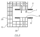
- FIG. 9 shows an alternative embodiment of a magnetic yoke 25, which has the shape of a C-arm.
- This C-arm comprises a vertical yoke part 26 and an upper transverse yoke part 27 and a lower one Transverse yoke part 28.
- the magnetic yoke 25 is basic except for the outer shape constructed with the same components as the magnetic yoke 2, so that the same Parts with the same reference numerals. So are the vertical yoke part 26 the upper transverse yoke part 27 and the lower transverse yoke part 28 cuboidal ferrite blocks 16 constructed and includes the magnetic yoke 25 pole pieces 7, 8 with these correspondingly assigned magnet coils 9, 10.
- Such a C-arm has the advantage of good accessibility, however Disadvantage that it creates a larger stray field.
Landscapes
- Health & Medical Sciences (AREA)
- Engineering & Computer Science (AREA)
- Animal Behavior & Ethology (AREA)
- Nuclear Medicine, Radiotherapy & Molecular Imaging (AREA)
- Radiology & Medical Imaging (AREA)
- Life Sciences & Earth Sciences (AREA)
- Biomedical Technology (AREA)
- General Health & Medical Sciences (AREA)
- Public Health (AREA)
- Veterinary Medicine (AREA)
- Power Engineering (AREA)
- Magnetic Treatment Devices (AREA)
- Thermotherapy And Cooling Therapy Devices (AREA)
Claims (19)
- Applicateur de champ magnétique pour le chauffage de substances ou de corps solides magnétiques ou magnétisables dans des tissus biologiques,
présentant une carcasse d'aimant (2 ; 25) avec deux épanouissements polaires (7, 8) situés sur la carcasse d'aimant qui sont espacés par un entrefer et en vis-à-vis, et ayant deux bobines d'excitation (9, 10) qui sont affectées chacune à un épanouissement polaire et destinées à la génération d'un champ magnétique alternant,
caractérisé en ce que la carcasse d'aimant (2; 25) et les épanouissements polaires (7, 8) sont constitués d'éléments de ferrite (16, 22) assemblés, et
en ce que les bobines d'excitation (9, 10) sont sous forme de galettes présentant au moins une spire de forme hélicoïdale, qui sont assignées chacune à un épanouissement polaire (7, 8) et qui entourent l'extrémité de l'épanouissement polaire correspondant avec une lumière périphérique entre la bobine d'excitation et l'épanouissement polaire (a). - Applicateur de champ magnétique selon la revendication 1, caractérisé en ce que les bobines d'excitation (9, 10) présentent une ou plusieurs spires de forme hélicoïdale préparées à partir de fil de cuivre en toron torsadé.
- Applicateur de champ magnétique selon la revendication 1 ou 2, caractérisé en ce que les épanouissements polaires (7, 8) sont façonnées en forme circulaire, en vue de dessus, et sont en vis-à-vis, de sorte que les surfaces circulaires d'épanouissement polaire sont disposées parallèlement et en vis-à-vis l'une par rapport l'autre, séparées par l'entrefer (12), et
en ce que les bobines d'excitation (9, 10) sont façonnées en forme circulaire, en correspondance. - Applicateur de champ magnétique selon l'une quelconque des revendications 1 à 3, caractérisé en ce que la lumière entre la bobine d'excitation et l'épanouissement polaire (a) présente une taille comprise entre 0,07 fois et 0,1 fois du diamètre (d) de l'épanouissement polaire, et
en ce que la bobine d'excitation (7, 8) est disposée approximativement en affleurement par rapport à la surface de l'extrémité de l'épanouissement polaire, l'arête périphérique de la surface de l'extrémité de l'épanouissement polaire étant arrondie. - Applicateur de champ magnétique selon l'une quelconque des revendications 1 à 4, caractérisé en ce que le diamètre (d) de l'épanouissement polaire est plus grand que l'entrefer (12).
- Applicateur de champ magnétique selon l'une quelconque des revendications 1 à 5, caractérisé en ce que la carcasse d'aimant (2; 25) est composée d'éléments de ferrite (16) parallélépipédiques dont les surfaces sont éventuellement libérées de couches frittées et qu'elles sont rectifiées pour obtenir des faces planes et parallèles, et
en ce que les épanouissements polaires (7, 8) ronds sont composés d'éléments de ferrite (22) qui présentent, vus de dessus, une forme cunéiforme, et que l'on a traité de manière similaire. - Applicateur de champ magnétique selon l'une quelconque des revendications 1 à 6, caractérisé en ce que les éléments de ferrite (16) parallélépipédiques sont constitués de plaques de ferrite (18) alignées l'une derrière l'autre, disposées dans la carcasse d'aimant (2; 25) et dirigées le long du flux magnétique, qui sont séparées l'une de l'autre par une fente d'isolation/de refroidissement (19) située de manière transversale par rapport au flux magnétique et permettant une circulation de l'air de refroidissement, et qui sont disposées l'une contre l'autre, dans le sens longitudinal du flux magnétique, en présentant seulement une discontinuité de contact (s2) étroite.
- Applicateur de champ magnétique selon la revendication 7, caractérisé en ce que l'on introduit dans la fente d'isolation/de refroidissement (19), de préférence dans ses zones latérales, des séparateurs (20) constitués de matière synthétique, et en ce que l'on colle les plaques de ferrite (18) par l'intermédiaire des séparateurs (20) afin d'obtenir les éléments de ferrite (16) en tant qu'éléments de carcasse.
- Applicateur de champ magnétique selon la revendication 6, caractérisé en ce que l'on insère des séparateurs entre les éléments de ferrite (22) cunéiformes afin de former des fentes d'isolation/de refroidissement (23), séparateurs qui servent éventuellement à coller des éléments de ferrite (22) voisins afin d'obtenir un épanouissement polaire, et
en ce que l'on prévoit une ouverture (24) axiale tubulaire afin de former à chaque fois un épanouissement polaire (7, 8) tubulaire, ouverture (24) qui permet l'introduction de l'air de refroidissement. - Applicateur de champ magnétique selon l'une quelconque des revendications 1 à 9, caractérisé en ce que la carcasse d'aimant (2; 25) est constituée d'au moins une partie verticale de carcasse (3, 4; 26) à laquelle on connecte deux parties transversales de carcasse (5, 6; 27, 28), et
en ce que l'on connecte les épanouissements polaires (7, 8) en vis-à-vis aux parties transversales de carcasse (5, 6; 27, 28),
au moins une partie transversale de carcasse (6) étant ajustable par rapport à l'autre partie transversale de carcasse (5) afin de pouvoir faire varier l'écartement de l'entrefer. - Applicateur de champ magnétique selon l'une quelconque des revendications 1 à 10, caractérisé en ce que des discontinuités magnétiques obligatoires (s1) sont prévues, qui présentent de préférence un interstice allant de 2 mm à 3 mm, et qui sont situées au niveau des zones de transition à tolérance entre les éléments de carcasse d'aimant, en particulier au niveau des zones de transition entre les parties transversales de carcasse (6) que l'on peut ajuster l'une par rapport à l'autre et les parties verticales de carcasse (3, 4) et/ou au niveau des zones de transition entre les parties transversales de carcasse (5, 6) et les épanouissements polaires (7, 8), afin de réguler le flux magnétique, les interstices de ces discontinuités magnétiques obligatoires (s1) étant très grands par rapport aux discontinuités de contact (s2), en particulier dans la zone d'ajustement des parties transversales de la carcasse.
- Applicateur de champ magnétique selon l'une quelconque des revendications 1 à 11, caractérisé en ce que la carcasse d'aimant (25) présente une forme en C dans laquelle la zone d'ouverture du C correspond à l'entrefer formé par les épanouissements polaires.
- Applicateur de champ magnétique selon l'une quelconque des revendications 1 à 11, caractérisé en ce que la carcasse d'aimant (2) présente une forme en M sous forme d'une disposition à trois branches comprenant deux parties verticales de carcasse (3, 4) parallèles, écartées et présentant les mêmes propriétés géométriques, et deux parties transversales de carcasse (5, 6) connectées entre les premières et présentant, dans leur centre, des épanouissements polaires (7, 8) dirigés l'un vers l'autre, au moins une partie transversale de carcasse (6) et son épanouissement polaire (8) connecté ainsi qu'une bobine d'excitation (10) correspondante étant, en tant que composant, ajustable par rapport à l'autre partie transversale de carcasse (5), afin de régler l'écartement de l'entrefer.
- Applicateur de champ magnétique selon la revendication 13, caractérisé en ce que l'on monte de manière fixe un composant constitué d'une partie transversale inférieure de carcasse (6) et l'épanouissement polaire (8) correspondant avec sa bobine d'excitation (10), et
en ce que l'on peut ajuster, par rapport à ce composant, un portique constitué des deux parties verticales de carcasse (3, 4) et de la partie transversale de carcasse supérieure (5) ainsi que l'épanouissement polaire (7) correspondant avec sa bobine d'excitation (9), au moyen d'un dispositif d'ajustement vertical (11) destiné au réglage de l'écartement de l'entrefer. - Applicateur de champ magnétique selon la revendication 14, caractérisé en ce que le dispositif d'ajustage vertical est constitué d'au moins un mécanisme d'entraínement linéaire entraínable par moteur, qui saisit les parties verticales de carcasse (3, 4) par le bas, en particulier d'un entraínement à broche autobloquant (11).
- Applicateur de champ magnétique selon l'une quelconque des revendications 1 à 15, caractérisé en ce que la carcasse d'aimant (2; 25) est logée dans un bâti qui permet, de plus, l'introduction et la circulation de l'air de refroidissement.
- Applicateur de champ magnétique selon l'une quelconque des revendications 1 à 16, caractérisé en ce que l'entrefer (12) est limité par des couronnes limitatives de champ, de part et d'autre des parties verticales de carcasse (3, 4; 26), et/ou par des cloisons étanches (14, 15) qui délimitent un espace d'insertion et qui sont éventuellement déplaçables, l'une par rapport à l'autre, dans le sens vertical.
- Applicateur de champ magnétique selon l'une quelconque des revendications 1 à 17, caractérisé en ce que le tissu à exposer au champ est une zone de tumeur d'un patient dans laquelle on peut introduire un liquide magnétique présentant de préférence des nanoparticules magnétiques et/ou magnétisables, la zone de tumeur pouvant être chauffée localement à une température de préférence supérieure à 41°C environ.
- Applicateur de champ magnétique selon la revendication 18, caractérisé en ce que l'on applique un champ magnétique alternatif présentant une intensité du champ magnétique comprise de préférence entre 10 kA/m et 15 kA/m et une fréquence comprise de préférence entre 50 kHz et 100 kHz.
Applications Claiming Priority (3)
| Application Number | Priority Date | Filing Date | Title |
|---|---|---|---|
| DE19937492 | 1999-08-07 | ||
| DE19937492A DE19937492C2 (de) | 1999-08-07 | 1999-08-07 | Magnetfeldapplikator zur Aufheizung von magnetischen oder magnetisierbaren Substanzen oder Festkörpern in biologischem Gewebe |
| PCT/EP2000/006836 WO2001010501A1 (fr) | 1999-08-07 | 2000-07-18 | Applicateur de champ magnetique pour le chauffage de substances ou de corps solides magnetiques ou magnetisables dans des tissus biologiques |
Publications (2)
| Publication Number | Publication Date |
|---|---|
| EP1102609A1 EP1102609A1 (fr) | 2001-05-30 |
| EP1102609B1 true EP1102609B1 (fr) | 2002-11-06 |
Family
ID=7917694
Family Applications (1)
| Application Number | Title | Priority Date | Filing Date |
|---|---|---|---|
| EP00956196A Expired - Lifetime EP1102609B1 (fr) | 1999-08-07 | 2000-07-18 | Applicateur de champ magnetique pour le chauffage de substances ou de corps solides magnetiques ou magnetisables dans des tissus biologiques |
Country Status (13)
| Country | Link |
|---|---|
| US (1) | US6635009B2 (fr) |
| EP (1) | EP1102609B1 (fr) |
| JP (1) | JP4245295B2 (fr) |
| KR (1) | KR100810606B1 (fr) |
| CN (1) | CN1156320C (fr) |
| AT (1) | ATE227148T1 (fr) |
| AU (1) | AU773989B2 (fr) |
| BR (1) | BR0007016B1 (fr) |
| CA (1) | CA2344885C (fr) |
| DE (2) | DE19937492C2 (fr) |
| IL (2) | IL142409A0 (fr) |
| TR (1) | TR200101023T1 (fr) |
| WO (1) | WO2001010501A1 (fr) |
Cited By (2)
| Publication number | Priority date | Publication date | Assignee | Title |
|---|---|---|---|---|
| EP1747763A1 (fr) | 2005-07-29 | 2007-01-31 | Peter Feucht | Seringue d'injection avec une aiguille d'injection |
| EP2105163A1 (fr) | 2008-03-28 | 2009-09-30 | Magforce Nanotechnologies AG | Dispositif d'application de champ magnétique alternatif destiné au chauffage de substances magnétiques ou pouvant être magnétisées dans des tissus biologiques |
Families Citing this family (33)
| Publication number | Priority date | Publication date | Assignee | Title |
|---|---|---|---|---|
| DE10109105C2 (de) * | 2001-02-24 | 2003-01-09 | Mfh Hyperthermiesysteme Gmbh | Magnetspulenanordnung eines Magnetfeldapplikators zur Aufheizung von magnetischen oder magnetisierbaren Substanzen oder Festkörpern in biologischem Gewebe |
| DE10113659B4 (de) * | 2001-03-21 | 2006-10-26 | Triton BioSystems Inc., Chelmsford | Metallischer medizinischer Stent |
| US6997863B2 (en) * | 2001-07-25 | 2006-02-14 | Triton Biosystems, Inc. | Thermotherapy via targeted delivery of nanoscale magnetic particles |
| US7951061B2 (en) * | 2001-07-25 | 2011-05-31 | Allan Foreman | Devices for targeted delivery of thermotherapy, and methods related thereto |
| US7731648B2 (en) | 2001-07-25 | 2010-06-08 | Aduro Biotech | Magnetic nanoscale particle compositions, and therapeutic methods related thereto |
| KR20010114201A (ko) * | 2001-12-12 | 2001-12-29 | 이강호 | 강자성 나노와이어의 제조방법과 제조장치 |
| US6850804B2 (en) * | 2002-01-18 | 2005-02-01 | Calfacior Corporation | System method and apparatus for localized heating of tissue |
| DE10238853A1 (de) * | 2002-08-24 | 2004-03-04 | Philips Intellectual Property & Standards Gmbh | Verfahren zur lokalen Erwärmung mit magnetischen Partikeln |
| CN100464802C (zh) * | 2002-12-31 | 2009-03-04 | 华中科技大学同济医学院 | 高梯度磁场发生装置 |
| US20040156846A1 (en) * | 2003-02-06 | 2004-08-12 | Triton Biosystems, Inc. | Therapy via targeted delivery of nanoscale particles using L6 antibodies |
| WO2004091393A1 (fr) * | 2003-04-15 | 2004-10-28 | Philips Intellectual Property & Standards Gmbh | Agencement permettant d'agir sur des particules magnetiques |
| JP4583369B2 (ja) * | 2003-04-15 | 2010-11-17 | コーニンクレッカ フィリップス エレクトロニクス エヌ ヴィ | 磁性粒子に影響を与える方法及び装置 |
| US7824324B2 (en) * | 2005-07-27 | 2010-11-02 | Neuronetics, Inc. | Magnetic core for medical procedures |
| US20080319247A1 (en) * | 2007-06-21 | 2008-12-25 | Philadelphia Health & Education Corporation D/B/A Drexel University College Of Medicine | Method of local therapy using magnetizable thermoplastic implant |
| KR101022244B1 (ko) * | 2008-08-29 | 2011-03-16 | (주) 엠큐브테크놀로지 | 방열특성이 우수한 저소음 자기장 발생 장치 |
| WO2010026638A1 (fr) * | 2008-09-04 | 2010-03-11 | 株式会社ナノセラピー研究所 | Trousse de thérapie hyperthermique pour tumeur maligne comprenant un anticorps anti-lymphocyte t régulateur et une microparticule magnétique, et thérapie hyperthermique utilisant la trousse |
| DE102009058769A1 (de) | 2009-12-16 | 2011-06-22 | MagForce Nanotechnologies AG, 10589 | Temperaturabhängige Aktivierung von katalytischen Nukleinsäuren zur kontrollierten Wirkstofffreisetzung |
| US8968171B2 (en) | 2011-01-24 | 2015-03-03 | Endomagnetics Limited | System for correlating energy field characteristics with target particle characteristics in the application of an energy field to a living organism for imaging and treatment of invasive agents |
| US8757166B2 (en) | 2011-01-24 | 2014-06-24 | Actium BioSystems, LLC | System for defining energy field characteristics to illuminate nano-particles used to treat invasive agents |
| US20120190911A1 (en) * | 2011-01-24 | 2012-07-26 | Actium BioSystems, LLC | Low temperature hyperthermia system for therapeutic treatment of invasive agents |
| US20120190979A1 (en) | 2011-01-24 | 2012-07-26 | Actium BioSystems, LLC | System for automatically amending energy field characteristics in the application of an energy field to a living organism for treatment of invasive agents |
| EP2695484B1 (fr) * | 2011-04-05 | 2015-10-14 | Comaintel, Inc. | Bobine de travail de chauffage par induction |
| CA2846094C (fr) | 2011-08-26 | 2017-06-20 | Actium BioSystems, LLC | Appareil de generation de champ energetique pour traitement du cancer dans des cavites corporelles et des parties de type cavite |
| US9005151B2 (en) | 2011-09-07 | 2015-04-14 | Choon Kee Lee | Thermal apparatus |
| RU2624315C2 (ru) * | 2011-11-16 | 2017-07-03 | Конинклейке Филипс Н.В. | Устройство и способ оказания влияния и обнаружения магнитных частиц, имеющие большое поле зрения |
| AT517737B1 (de) * | 2015-10-02 | 2018-07-15 | Pontemed Ag | Magnetische Stimulationsvorrichtung |
| CN107067911A (zh) * | 2017-04-28 | 2017-08-18 | 浙江和也健康科技有限公司 | 一种用于生物学研究的均匀磁场发生装置 |
| CN107393381B (zh) * | 2017-07-25 | 2019-11-26 | 重庆科技学院 | 一种可调稳恒磁场实验装置的使用方法 |
| CN107274767B (zh) * | 2017-07-25 | 2019-12-17 | 重庆科技学院 | 一种可调稳恒磁场实验装置 |
| KR102428203B1 (ko) * | 2020-02-25 | 2022-08-04 | 서울대학교산학협력단 | 질병 치료를 위한 교류 자기장 발생 장치 및 시스템 |
| CN111580031B (zh) * | 2020-04-29 | 2025-04-22 | 杭州智见控股集团有限公司 | 一种大范围高均匀度磁场的永磁系统 |
| KR102510348B1 (ko) * | 2020-07-31 | 2023-03-16 | 주식회사 리메드 | 자기 발생 치료장치 |
| KR102647772B1 (ko) * | 2023-03-10 | 2024-03-14 | 주식회사 케이원메드글로벌 | 열관리 기능을 구비한 전자기장 치료기용 전자기장 출력핸들유닛 |
Family Cites Families (18)
| Publication number | Priority date | Publication date | Assignee | Title |
|---|---|---|---|---|
| US3763342A (en) * | 1971-08-06 | 1973-10-02 | Thermatool Corp | Air cooled magnetic structure for use in high frequency welding and heating |
| JPS57143804A (en) * | 1981-02-28 | 1982-09-06 | Futaba Denjiki Kk | Cylindrical iron core made of segmental pieces |
| DE3306391A1 (de) * | 1983-02-24 | 1984-08-30 | Forschungsinstitut Manfred von Ardenne, DDR 8051 Dresden | Einrichtung zur hyperthermie des menschlichen koerpers |
| GB2144609B (en) * | 1983-08-03 | 1987-02-18 | Davy Mckee | Variable width inductor for induction heating |
| FR2566986B1 (fr) * | 1984-06-28 | 1986-09-19 | Electricite De France | Dispositif a induction electromagnetique pour le chauffage d'elements metalliques |
| DE3431314A1 (de) * | 1984-08-25 | 1986-03-06 | Omecon Elektronik GmbH, 8012 Ottobrunn | Anordnung zur durchfuehrung der medizinischen hyperthermie |
| DE3633682A1 (de) | 1986-10-03 | 1988-04-14 | Hess Joachim | Heizblock zur beheizung von ventilbloecken und messgeraeten |
| US5123989A (en) * | 1989-06-14 | 1992-06-23 | Toda Kogyo Corporation | Resin-bonding method |
| US5197940A (en) * | 1990-01-29 | 1993-03-30 | Hypertherm Corp. | Local application tumor treatment apparatus |
| SE9000989L (sv) * | 1990-03-20 | 1991-09-21 | Ulf Thelander | Upphettningsanordning |
| US5067952A (en) * | 1990-04-02 | 1991-11-26 | Gudov Vasily F | Method and apparatus for treating malignant tumors by local hyperpyrexia |
| DE4344341A1 (de) | 1993-12-23 | 1995-07-06 | Elpag Ag Chur | Rohrheizkörper mit Überlastsicherung und Temperaturfühler |
| DE4442690A1 (de) * | 1994-11-30 | 1996-06-05 | Delma Elektro Med App | Einrichtung zur interstitiellen Thermotherapie von Tumoren mit Hochfrequenzströmen |
| AUPN978296A0 (en) * | 1996-05-10 | 1996-05-30 | Gray, Bruce N | Targeted hysteresis hyperthermia as a method for treating cancer |
| DE19627817A1 (de) * | 1996-07-10 | 1998-01-15 | Rudolf Pack Gmbh & Co Kg | Flachspule |
| AUPP008197A0 (en) * | 1997-10-29 | 1997-11-20 | Paragon Medical Limited | Improved targeted hysteresis hyperthermia as a method for treating diseased tissue |
| DE29801073U1 (de) * | 1998-01-23 | 1998-08-06 | Wampfler AG, 79576 Weil am Rhein | Ferritkern |
| DE19941901A1 (de) | 1999-09-02 | 2001-03-29 | Bleckmann Gmbh Lamprechtshause | Rohrheizkörper mit NTC/PTC-Absicherung |
-
1999
- 1999-08-07 DE DE19937492A patent/DE19937492C2/de not_active Expired - Fee Related
-
2000
- 2000-07-18 TR TR2001/01023T patent/TR200101023T1/xx unknown
- 2000-07-18 WO PCT/EP2000/006836 patent/WO2001010501A1/fr not_active Ceased
- 2000-07-18 AU AU68241/00A patent/AU773989B2/en not_active Expired
- 2000-07-18 KR KR1020017004383A patent/KR100810606B1/ko not_active Expired - Lifetime
- 2000-07-18 JP JP2001515011A patent/JP4245295B2/ja not_active Expired - Lifetime
- 2000-07-18 CA CA002344885A patent/CA2344885C/fr not_active Expired - Lifetime
- 2000-07-18 IL IL14240900A patent/IL142409A0/xx active IP Right Grant
- 2000-07-18 DE DE50000720T patent/DE50000720D1/de not_active Expired - Lifetime
- 2000-07-18 AT AT00956196T patent/ATE227148T1/de active
- 2000-07-18 CN CNB008016313A patent/CN1156320C/zh not_active Expired - Lifetime
- 2000-07-18 BR BRPI0007016-5A patent/BR0007016B1/pt not_active IP Right Cessation
- 2000-07-18 EP EP00956196A patent/EP1102609B1/fr not_active Expired - Lifetime
-
2001
- 2001-01-18 US US09/764,927 patent/US6635009B2/en not_active Expired - Lifetime
- 2001-04-03 IL IL142409A patent/IL142409A/en unknown
Cited By (6)
| Publication number | Priority date | Publication date | Assignee | Title |
|---|---|---|---|---|
| EP1747763A1 (fr) | 2005-07-29 | 2007-01-31 | Peter Feucht | Seringue d'injection avec une aiguille d'injection |
| EP2105163A1 (fr) | 2008-03-28 | 2009-09-30 | Magforce Nanotechnologies AG | Dispositif d'application de champ magnétique alternatif destiné au chauffage de substances magnétiques ou pouvant être magnétisées dans des tissus biologiques |
| WO2009118091A1 (fr) * | 2008-03-28 | 2009-10-01 | Magforce Nanotechnologies Ag | Dispositif d'application de champ magnétique alternatif pour le chauffage de substances magnétiques ou magnétisables dans un tissu biologique |
| JP2011515165A (ja) * | 2008-03-28 | 2011-05-19 | マグフォース ナノテクノロジー アーゲー | 生物組織内の磁性体または磁化可能物質を加熱する交番磁界適用装置 |
| RU2499617C2 (ru) * | 2008-03-28 | 2013-11-27 | Магфорс Нанотекнолоджиз Аг | Устройство для приложения магнитного переменного поля для нагрева магнитных или намагничиваемых веществ в биологической ткани |
| US8688229B2 (en) | 2008-03-28 | 2014-04-01 | Magforce Ag | Alternating magnetic field application device for heating magnetic or magnetizable substances in biological tissue |
Also Published As
| Publication number | Publication date |
|---|---|
| EP1102609A1 (fr) | 2001-05-30 |
| DE19937492C2 (de) | 2001-08-23 |
| CN1156320C (zh) | 2004-07-07 |
| KR20020012531A (ko) | 2002-02-16 |
| ATE227148T1 (de) | 2002-11-15 |
| CA2344885A1 (fr) | 2001-02-15 |
| AU6824100A (en) | 2001-03-05 |
| CA2344885C (fr) | 2009-03-24 |
| JP2003506163A (ja) | 2003-02-18 |
| DE50000720D1 (de) | 2002-12-12 |
| DE19937492A1 (de) | 2001-05-10 |
| US6635009B2 (en) | 2003-10-21 |
| IL142409A (en) | 2007-07-24 |
| KR100810606B1 (ko) | 2008-03-06 |
| IL142409A0 (en) | 2002-03-10 |
| JP4245295B2 (ja) | 2009-03-25 |
| TR200101023T1 (tr) | 2001-08-21 |
| BR0007016B1 (pt) | 2011-08-23 |
| WO2001010501A1 (fr) | 2001-02-15 |
| US20010012912A1 (en) | 2001-08-09 |
| AU773989B2 (en) | 2004-06-10 |
| BR0007016A (pt) | 2001-06-19 |
| CN1319029A (zh) | 2001-10-24 |
Similar Documents
| Publication | Publication Date | Title |
|---|---|---|
| EP1102609B1 (fr) | Applicateur de champ magnetique pour le chauffage de substances ou de corps solides magnetiques ou magnetisables dans des tissus biologiques | |
| EP1098676B1 (fr) | Applicateur de champ magnetique pour le chauffage de substances ou de corps solides magnetiques ou magnetisables dans des tissus biologiques | |
| US5099756A (en) | Radio frequency thermotherapy | |
| EP2105163B1 (fr) | Dispositif d'application de champ magnétique alternatif destiné au chauffage de substances magnétiques ou pouvant être magnétisées dans des tissus biologiques | |
| DE10109105C2 (de) | Magnetspulenanordnung eines Magnetfeldapplikators zur Aufheizung von magnetischen oder magnetisierbaren Substanzen oder Festkörpern in biologischem Gewebe | |
| KR102234149B1 (ko) | 자성 물질 발열 기반의 교류 자기장 발생 장치 | |
| EP1981592A1 (fr) | Applicateur de champ magnetique | |
| DD234367A1 (de) | Intracavitaerer rf-huelsenapplikator | |
| DE10220680A1 (de) | Applikator für die Tiefenhyperthermie |
Legal Events
| Date | Code | Title | Description |
|---|---|---|---|
| PUAI | Public reference made under article 153(3) epc to a published international application that has entered the european phase |
Free format text: ORIGINAL CODE: 0009012 |
|
| 17P | Request for examination filed |
Effective date: 20001229 |
|
| AK | Designated contracting states |
Kind code of ref document: A1 Designated state(s): AT BE CH CY DE DK ES FI FR GB GR IE IT LI LU MC NL |
|
| AX | Request for extension of the european patent |
Free format text: AL;LT;LV;MK;RO;SI |
|
| GRAG | Despatch of communication of intention to grant |
Free format text: ORIGINAL CODE: EPIDOS AGRA |
|
| GRAG | Despatch of communication of intention to grant |
Free format text: ORIGINAL CODE: EPIDOS AGRA |
|
| GRAH | Despatch of communication of intention to grant a patent |
Free format text: ORIGINAL CODE: EPIDOS IGRA |
|
| 17Q | First examination report despatched |
Effective date: 20020425 |
|
| GRAH | Despatch of communication of intention to grant a patent |
Free format text: ORIGINAL CODE: EPIDOS IGRA |
|
| GRAA | (expected) grant |
Free format text: ORIGINAL CODE: 0009210 |
|
| AK | Designated contracting states |
Kind code of ref document: B1 Designated state(s): AT BE CH CY DE DK ES FI FR GB GR IE IT LI LU MC NL PT SE |
|
| PG25 | Lapsed in a contracting state [announced via postgrant information from national office to epo] |
Ref country code: FI Free format text: LAPSE BECAUSE OF FAILURE TO SUBMIT A TRANSLATION OF THE DESCRIPTION OR TO PAY THE FEE WITHIN THE PRESCRIBED TIME-LIMIT Effective date: 20021106 Ref country code: IE Free format text: LAPSE BECAUSE OF FAILURE TO SUBMIT A TRANSLATION OF THE DESCRIPTION OR TO PAY THE FEE WITHIN THE PRESCRIBED TIME-LIMIT Effective date: 20021106 Ref country code: GR Free format text: LAPSE BECAUSE OF FAILURE TO SUBMIT A TRANSLATION OF THE DESCRIPTION OR TO PAY THE FEE WITHIN THE PRESCRIBED TIME-LIMIT Effective date: 20021106 |
|
| REF | Corresponds to: |
Ref document number: 227148 Country of ref document: AT Date of ref document: 20021115 Kind code of ref document: T |
|
| REG | Reference to a national code |
Ref country code: GB Ref legal event code: FG4D Free format text: NOT ENGLISH |
|
| REG | Reference to a national code |
Ref country code: CH Ref legal event code: EP |
|
| REG | Reference to a national code |
Ref country code: IE Ref legal event code: FG4D Free format text: GERMAN |
|
| REF | Corresponds to: |
Ref document number: 50000720 Country of ref document: DE Date of ref document: 20021212 |
|
| REG | Reference to a national code |
Ref country code: CH Ref legal event code: NV Representative=s name: PA ALDO ROEMPLER |
|
| PG25 | Lapsed in a contracting state [announced via postgrant information from national office to epo] |
Ref country code: DK Free format text: LAPSE BECAUSE OF FAILURE TO SUBMIT A TRANSLATION OF THE DESCRIPTION OR TO PAY THE FEE WITHIN THE PRESCRIBED TIME-LIMIT Effective date: 20030206 Ref country code: SE Free format text: LAPSE BECAUSE OF FAILURE TO SUBMIT A TRANSLATION OF THE DESCRIPTION OR TO PAY THE FEE WITHIN THE PRESCRIBED TIME-LIMIT Effective date: 20030206 Ref country code: PT Free format text: LAPSE BECAUSE OF FAILURE TO SUBMIT A TRANSLATION OF THE DESCRIPTION OR TO PAY THE FEE WITHIN THE PRESCRIBED TIME-LIMIT Effective date: 20030206 |
|
| GBT | Gb: translation of ep patent filed (gb section 77(6)(a)/1977) |
Effective date: 20030218 |
|
| ET | Fr: translation filed | ||
| PG25 | Lapsed in a contracting state [announced via postgrant information from national office to epo] |
Ref country code: ES Free format text: LAPSE BECAUSE OF FAILURE TO SUBMIT A TRANSLATION OF THE DESCRIPTION OR TO PAY THE FEE WITHIN THE PRESCRIBED TIME-LIMIT Effective date: 20030529 |
|
| PG25 | Lapsed in a contracting state [announced via postgrant information from national office to epo] |
Ref country code: CY Free format text: LAPSE BECAUSE OF FAILURE TO SUBMIT A TRANSLATION OF THE DESCRIPTION OR TO PAY THE FEE WITHIN THE PRESCRIBED TIME-LIMIT Effective date: 20030718 Ref country code: LU Free format text: LAPSE BECAUSE OF NON-PAYMENT OF DUE FEES Effective date: 20030718 |
|
| REG | Reference to a national code |
Ref country code: IE Ref legal event code: FD4D Ref document number: 1102609E Country of ref document: IE |
|
| PG25 | Lapsed in a contracting state [announced via postgrant information from national office to epo] |
Ref country code: BE Free format text: LAPSE BECAUSE OF NON-PAYMENT OF DUE FEES Effective date: 20030731 Ref country code: MC Free format text: LAPSE BECAUSE OF NON-PAYMENT OF DUE FEES Effective date: 20030731 |
|
| PLBE | No opposition filed within time limit |
Free format text: ORIGINAL CODE: 0009261 |
|
| STAA | Information on the status of an ep patent application or granted ep patent |
Free format text: STATUS: NO OPPOSITION FILED WITHIN TIME LIMIT |
|
| 26N | No opposition filed |
Effective date: 20030807 |
|
| BERE | Be: lapsed |
Owner name: *MFH HYPERTHERMIESYSTEME G.M.B.H. Effective date: 20030731 |
|
| REG | Reference to a national code |
Ref country code: CH Ref legal event code: PCAR Free format text: ALDO ROEMPLER PATENTANWALT;BRENDENWEG 11 POSTFACH 154;9424 RHEINECK (CH) |
|
| REG | Reference to a national code |
Ref country code: FR Ref legal event code: PLFP Year of fee payment: 17 |
|
| REG | Reference to a national code |
Ref country code: FR Ref legal event code: PLFP Year of fee payment: 18 |
|
| REG | Reference to a national code |
Ref country code: FR Ref legal event code: PLFP Year of fee payment: 19 |
|
| REG | Reference to a national code |
Ref country code: DE Ref legal event code: R082 Ref document number: 50000720 Country of ref document: DE Representative=s name: NEUBAUER LIEBL BIERSCHNEIDER MASSINGER, DE Ref country code: DE Ref legal event code: R082 Ref document number: 50000720 Country of ref document: DE Representative=s name: NEUBAUER LIEBL BIERSCHNEIDER, DE Ref country code: DE Ref legal event code: R081 Ref document number: 50000720 Country of ref document: DE Owner name: MAGFORCE AG, DE Free format text: FORMER OWNER: MFH HYPERTHERMIESYSTEME GMBH, 12247 BERLIN, DE |
|
| REG | Reference to a national code |
Ref country code: DE Ref legal event code: R082 Ref document number: 50000720 Country of ref document: DE Representative=s name: NEUBAUER LIEBL BIERSCHNEIDER MASSINGER, DE Ref country code: DE Ref legal event code: R082 Ref document number: 50000720 Country of ref document: DE Representative=s name: NEUBAUER LIEBL BIERSCHNEIDER, DE Ref country code: DE Ref legal event code: R081 Ref document number: 50000720 Country of ref document: DE Owner name: MAGFORCE AG, DE Free format text: FORMER OWNER: MAGFORCE NANOTECHNOLOGIES GMBH, 14050 BERLIN, DE |
|
| REG | Reference to a national code |
Ref country code: DE Ref legal event code: R082 Ref document number: 50000720 Country of ref document: DE Representative=s name: NEUBAUER LIEBL BIERSCHNEIDER MASSINGER, DE Ref country code: DE Ref legal event code: R081 Ref document number: 50000720 Country of ref document: DE Owner name: MAGFORCE AG, DE Free format text: FORMER OWNER: MAGFORCE NANOTECHNOLOGIES AG, 10589 BERLIN, DE Ref country code: DE Ref legal event code: R082 Ref document number: 50000720 Country of ref document: DE Representative=s name: NEUBAUER LIEBL BIERSCHNEIDER, DE |
|
| REG | Reference to a national code |
Ref country code: GB Ref legal event code: 732E Free format text: REGISTERED BETWEEN 20181206 AND 20181212 |
|
| REG | Reference to a national code |
Ref country code: GB Ref legal event code: 732E Free format text: REGISTERED BETWEEN 20190801 AND 20190807 |
|
| PGFP | Annual fee paid to national office [announced via postgrant information from national office to epo] |
Ref country code: NL Payment date: 20190725 Year of fee payment: 20 |
|
| PGFP | Annual fee paid to national office [announced via postgrant information from national office to epo] |
Ref country code: DE Payment date: 20190829 Year of fee payment: 20 Ref country code: IT Payment date: 20190730 Year of fee payment: 20 Ref country code: FR Payment date: 20190730 Year of fee payment: 20 |
|
| PGFP | Annual fee paid to national office [announced via postgrant information from national office to epo] |
Ref country code: GB Payment date: 20190717 Year of fee payment: 20 Ref country code: AT Payment date: 20190725 Year of fee payment: 20 |
|
| PGFP | Annual fee paid to national office [announced via postgrant information from national office to epo] |
Ref country code: CH Payment date: 20190909 Year of fee payment: 20 |
|
| REG | Reference to a national code |
Ref country code: DE Ref legal event code: R071 Ref document number: 50000720 Country of ref document: DE |
|
| REG | Reference to a national code |
Ref country code: NL Ref legal event code: MK Effective date: 20200717 |
|
| REG | Reference to a national code |
Ref country code: CH Ref legal event code: PL |
|
| REG | Reference to a national code |
Ref country code: GB Ref legal event code: PE20 Expiry date: 20200717 |
|
| REG | Reference to a national code |
Ref country code: AT Ref legal event code: MK07 Ref document number: 227148 Country of ref document: AT Kind code of ref document: T Effective date: 20200718 |
|
| PG25 | Lapsed in a contracting state [announced via postgrant information from national office to epo] |
Ref country code: GB Free format text: LAPSE BECAUSE OF EXPIRATION OF PROTECTION Effective date: 20200717 |