EP1102679B1 - Unite d'impression - Google Patents
Unite d'impression Download PDFInfo
- Publication number
- EP1102679B1 EP1102679B1 EP99947251A EP99947251A EP1102679B1 EP 1102679 B1 EP1102679 B1 EP 1102679B1 EP 99947251 A EP99947251 A EP 99947251A EP 99947251 A EP99947251 A EP 99947251A EP 1102679 B1 EP1102679 B1 EP 1102679B1
- Authority
- EP
- European Patent Office
- Prior art keywords
- printing unit
- cylinder
- printing
- units
- impression cylinder
- Prior art date
- Legal status (The legal status is an assumption and is not a legal conclusion. Google has not performed a legal analysis and makes no representation as to the accuracy of the status listed.)
- Expired - Lifetime
Links
- 238000007639 printing Methods 0.000 title claims description 200
- 239000000463 material Substances 0.000 claims description 34
- 239000003086 colorant Substances 0.000 claims description 14
- 238000004519 manufacturing process Methods 0.000 claims description 12
- 238000007645 offset printing Methods 0.000 claims description 4
- 238000005516 engineering process Methods 0.000 description 2
- 238000009434 installation Methods 0.000 description 2
- 238000005406 washing Methods 0.000 description 2
- 238000006073 displacement reaction Methods 0.000 description 1
- 238000012423 maintenance Methods 0.000 description 1
- 238000000034 method Methods 0.000 description 1
Images


Classifications
-
- B—PERFORMING OPERATIONS; TRANSPORTING
- B41—PRINTING; LINING MACHINES; TYPEWRITERS; STAMPS
- B41F—PRINTING MACHINES OR PRESSES
- B41F7/00—Rotary lithographic machines
- B41F7/02—Rotary lithographic machines for offset printing
- B41F7/10—Rotary lithographic machines for offset printing using one impression cylinder co-operating with several transfer cylinders for printing on sheets or webs, e.g. satellite-printing units
Definitions
- the invention relates to a printing unit according to the Preamble of claim 1.
- a rotary offset printing machine in satellite design is known.
- a material web is printed by means of a ten-cylinder printing unit and a nine-cylinder printing unit. It is not intended to have the ten-cylinder printing unit produced as a nine-cylinder printing unit.
- EP 06 38 419 A1 describes a printing press, wherein Printing units are attached to a support frame. Individual modules, such as B. inking units or Cylinder groups are in the direction of the cylinder axes displaceable.
- DE 34 46 619 A1 shows a printing press in which two moving machine groups are described.
- Blanket cylinder and impression cylinders are in a stationary Machine group installed.
- DE-OS 21 65 185 discloses a printing unit with four Transfer cylinders and an impression cylinder.
- the invention has for its object a To create printing unit.
- Printing units a variety of production types be driven. For example, two Five-cylinder printing units each alone or together as Produce ten-cylinder printing units. In particular can use two five-cylinder printing units with different Cylinder arrangement used as a nine-cylinder printing unit become.
- the modular design allows an identical one Structure of the printing units; the modular system consists of just two basic elements.
- the modules can be put together in two ways become. In a first way, a module works as single printing unit independent of a second, while in a second way two modules to one common printing unit are coupled. One by 180 ° reversed installation, with a displacement of drive and Operating side is also possible. So are the drives of the printing units are not on a single one Arranged side of the printing press, the drives remain firmly assigned to a side frame.
- the inking units also remain the same. A Reversal of the direction of rotation is not necessary since the Combination of modules and their flexible assignment Production requirements 4/4, 4/2; 2/4 and 2/2 enable. Due to the possibility of moving Printing units can be operated from the inside. This operation from the inside is particularly important "W" printing units are advantageous because they do not Clipping devices are necessary.
- the arrangement of lifting and lowering work platforms in the intermediate frames and on the cylinder modules enables easy operation of the printing units.
- An offset rotary press or section an offset rotary printing press for example eight printing units 01 - 04; 06 - 09 in modular design on. Each of these printing units 01 - 04; 06 - 09 is as So-called.
- Five-cylinder printing unit executed and has in essentially two forme cylinders 11-14, e.g. B. Plate cylinder, two transfer cylinders 16 - 19, z. B. blanket cylinder and an impression cylinder 21; 22 (Satellite cylinder) on. Pins of this cylinder 11 - 14; 16-19; 21; 22 are on each side of the Offset rotary printing press in one each Side frame 23; 24 stored.
- impression cylinder 21; 22 on the associated transfer cylinder 16 -19, z. B. by means of an eccentric bush, three-ring bearing or Linear guide to start.
- each cylinder is 11-14; 16-19; 21; 22 with its own speed-controlled and / or position-controlled drive motor.
- each pair of form and transfer cylinders 11, 16; 12, 17; 13, 18; 14, 19 assign a drive motor and couple this pair in a form-fitting manner.
- the impression cylinder 21; 22 has its own drive motor or is connected to one of the pairs of form and transfer cylinders 11, 16; 12, 17; 13, 18; 14, 19 can be coupled.
- each printing unit 01 - 04; 06 - 09 only assign one drive motor.
- the drive motors are independent of the position and location of the printing units 01 - 04; 06 - 09 one side frame 23 each; 24 permanently assigned, so that in the case of the printing units 06-09 set up pivoted by 180 ° about a vertical, the drive motors of the printing units 06-09 set up pivoted to one another are arranged on the opposite sides SI, SII of the printing press.
- the drive motors of a printing unit 01 - 04; 06 - 09 can also on both side frames 23; 24 can be distributed, for example, the drive motors of impression cylinders 21; 22 and forme cylinders 11-14 on the first side frame 23; 24 and the drive motors of the transfer cylinders 16-19 on the second side frame 23; 24 arranged.
- a bridge printing unit 71 (FIG. 5) composed of two modules 72, 73, each with a pair of form and transfer cylinders 74; 76 are formed, one module 72 being arranged to the other module 73 pivoted through 180 ° about a vertical (FIG. 5).
- a pair of forme and transfer cylinders 74; 76 is supported in a pair of side frames 81, 87.
- This drive motor 79 is permanently assigned to a side frame 81.
- printing units With at least two within a printing press arranged printing units are at least their Cylinder and their side frames and the respective Side frame or associated with the respective cylinder Drive means (e.g. gears, gears, Drive motor) arranged pivoted about a vertical.
- cylinder Drive means e.g. gears, gears, Drive motor
- Each forme cylinder 11-14 is an inking unit 26 - 29 and a dampening unit 31 - 34 assigned, the Dampening unit 31 - 34 related to the production direction of the forme cylinder 11 - 14 seen, in front of the inking unit 26-29 is arranged.
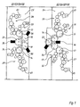
- a first type of printing unit 02; 04; 07; 09 close one of an axis of rotation 37 of the Impression cylinder 22 and an axis of rotation 38; 39 one assigned transfer cylinder 16; 17 laid down Straight line 41; 42 with one of the axis of rotation 38; 39 of Transfer cylinder 16; 17 and an axis of rotation 43; 44 of the forme cylinder 11; 12 defined straight lines 46; 47 an opening angle alpha in a range of 150 ° to 210 °, preferably 170 ° to 190 °.
- the of the Axis of rotation 38 of the first transfer cylinder 16 and Axis of rotation 37 of the impression cylinder 22 set Just 41 closes with one of the axis of rotation 39 of the second transfer cylinder 17 and the axis of rotation 37 of the impression cylinder 22 a straight line 42 a Opening angle beta in the range from 60 ° to 120 °, preferably 70 ° to 90 °.
- the cylinders 11, 12, 16, 17, 22 of the printing units 02; 04; 07; 09 of the first kind are arranged in a so-called "V" arrangement.
- the narrow cylinder arrangement of the V-printing unit 02; 04, 07; 09 makes it possible to use a washing device 36 to clean two cylinders at the same time.
- a second type of printing unit 01; 03; 06; 08 close one of an axis of rotation 48 of the Impression cylinder 21 and an axis of rotation 49; 51 one assigned transfer cylinder 18; 19 specified Lines 52; 53 with one of the axis of rotation 49; 51 of Transfer cylinder 18; 19 and an axis of rotation 54; 56 of the forme cylinder 13; 14 defined straight lines 57; 58 an opening angle delta in a range from 90 ° to 120 °, preferably 85 ° to 100 °.
- the cylinders 13, 14, 18, 19, 21 of the printing units 01; 03; 06; 08 of the second kind are arranged in a so-called "W" arrangement.
- the respective printing units 01, 02 or 03, 04 or 06, 07 or 08, 09 can each be operated independently of one another as opposing five-cylinder printing units, ie two opposing printing units 01, 02 or 03, 04 or 06, 07 or 08, 09 functionally form a ten-cylinder satellite printing unit in a first operating mode.
- the transfer cylinders 16, 17 and 18, 19 act with the respective impression cylinders 22 and 21 of the "V" printing unit 02; 04; 07; 09 and "W" printing unit together 01; 03; 06; 08th
- two five-cylinder printing units function functionally as a nine-cylinder satellite printing unit.
- the transfer cylinder 16; 17; 18; 19 a "V” printing unit 04; 07 and a "W” printing unit 03; 06 to the impression cylinder 22 of the "V” printing unit 04; 07 on and off.
- the impression cylinder 21 of the "W” printing unit 03; 06 is not involved in the printing process.
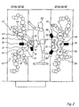
- inking units 26 - 29 are operated and maintained with two printing units 01, 02 or 03, 04 or 06, 07 or 08, 09 from the same side. This is why ink boxes 61 are the inking units, for example 26 - 29 of both printing units 01, 02 or 03, 04 or 06, 07 aligned to one side, d. H. in the on the upper floor are the color boxes 61 to the left and in the lower floor facing right.
- This material web 62 wraps around the impression cylinder 22 and is diagonally upwards between the two upper inking units 26, 28 of the "V” and “W” printing unit 07, 06 from the lower nine-cylinder printing unit onto the impression cylinder 22 of the upper "V” printing unit 04 led. Also in the upper nine-cylinder printing unit, the material web 62 wraps around the impression cylinder 22 of the upper "V” printing unit 04 and is moved down between the two lower inking units 27, 29 of the upper "V” and "W” printing units 04, 03 from the upper one Nine cylinder printing unit led.
- the material web 62 can also first at the top and then at the bottom be introduced.
- a first is installed in the lower nine-cylinder printing unit Side of the material web 62 and in the upper Nine cylinder printing unit becomes a second side of the Material web 62 printed in four colors.
- a material web 64 coming from below is fed from the outside between the lower forme cylinder 14 and the impression cylinder 21 to the impression cylinder 21 of the lower “W” printing unit 08.
- This material web 64 wraps around the impression cylinder 21 by approximately 180 ° and is discharged to the outside between the upper forme cylinder 13 and impression cylinder 21 from the "W” printing unit 08.
- This material web 64 is fed via guide rollers 63 between the upper right “V” and “W” printing units 02, 01 to the impression cylinder 22 of the upper “V” printing unit 02, wraps around this by about 80 ° and is between the upper, right "V” and “W” printing units 02, 01 are removed from the upper "V” printing unit 02.
- a first side of the material web 64 is printed in two colors and a second side of the material web 64 in the upper “V” printing unit 02 in two colors.
- Another material web 66 coming from below is fed via guide rollers 63 between the lower right “V” and “W” printing units 09, 08 to the impression cylinder 22 of the lower “V” printing unit 09, wrapping them around about 80 ° and is discharged between the lower right “V” and “W” printing units 09, 08 from the lower “V” printing unit 9.
- This material web 66 is fed from the outside between the lower forme cylinder 14 and the impression cylinder 21 to the impression cylinder 21 of the upper “W” printing unit 01.
- the material web 66 wraps around the impression cylinder 21 by approximately 180 ° and is discharged to the outside between the upper forme cylinder 13 and impression cylinder 21 from the "W” printing unit 01.
- a first side of the material web 66 is printed in two colors and a second side of the material web 66 in the upper “W” printing unit 01 in two colors.
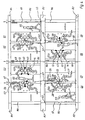
- a third mode of production (Fig. 4) are the two left printing units 03, 04 of the upper floor to each other spaced and therefore not coupled and the two left printing units 06, 07 of the lower floor are closed coupled to a nine-cylinder printing unit.
- the two right printing units 01, 02 of the upper floor are closed coupled to a nine-cylinder printing unit and the two right printing units 08, 09 of the lower floor spaced from each other.
- a material web 67 is guided by guide rollers 63 between the upper and lower levels from above between the two inking units 26, 28 of the "V” and “W” printing units 07, 06 onto the impression cylinder 22 of the lower “V” printing unit 07.
- This material web 67 wraps around the impression cylinder 22 of the "V” printing unit 07 and is moved upwards between the two upper inking units 26, 28 of the "V” and “W” printing unit 07, 06 from the lower nine-cylinder printing unit diagonally upwards via guide rollers 63 between the upper left “V” and “W” printing units 04, 03 on the impression cylinder 22 of the upper “V” printing unit 04.
- This material web 67 wraps around this impression cylinder 22 by approximately 80 ° and is discharged between the upper left “V” and “W” printing units 04, 03 from the upper “V” printing unit 04 inside.
- a first is installed in the lower nine-cylinder printing unit Side of the material web 67 four-colored and a second Side of web 67 in the upper "V" printing unit 04 printed in two colors.
- a material web 68 coming from below is fed from the outside between the lower forme cylinder 14 and the impression cylinder 21 to the impression cylinder 21 of the lower right "W” printing unit 08.
- This material web 68 wraps around the impression cylinder 21 by approximately 180 ° and is discharged to the outside between the upper forme cylinder 13 and impression cylinder 21 from the lower right "W” printing unit 08.
- This web of material 68 is fed via guide rollers 63 from the outside between the lower forme cylinder 14 and impression cylinder 21 to the impression cylinder 21 of the upper left “W” printing unit 03, wraps around it by approximately 180 ° and becomes between the upper forme cylinder 13 and impression cylinder 21 to the outside discharged from the upper left “W” printing unit 03.
- a first side of the material web 68 is printed in two colors and a second side of the material web 68 in the upper left "W” printing unit 03 is printed in two colors.
- Another web of material 69 is corresponding to the first material web 67 in one from the upper right "V” and "W” printing units 02, 01 formed Nine printing unit and in the lower right “V” printing unit 09 printed. This is a first Side of the material web 69 in the lower right “V” printing unit 09 printed in two colors. Subsequently becomes a second side of the web 69 in the upper Nine cylinder printing unit printed in four colors.
- V and "W” printing units 01-04; 06 - 09 can used as imprinter, d. H. while at least a pair of form and transfer cylinders to the Impression cylinder printing a web of material are employed, at least one forme cylinder is closed Set-up purposes adjustable.
- the printing units 01 - 04; 06 - 09 in modular design are arranged in a carrying device.
- This support device is, for example from three cross members 82; 83; 84, the one above the other spaced apart by means of vertically extending supports 86 are arranged.
- On this carrier are the Printing units 01 - 04; 06 - 09 attached.
- At Printing units 01 - 04; 06 - 09 the one above the other are arranged, d. H. on two floors, is the top one Printing unit 01 - 04 on a cross member 83; 84 or a support 86 of the support device attached.
- This Cross member 83; 84 is above the lower printing unit Arranged 06 - 09.
- the cross members 82-84 can be in individual segments can be divided.
Landscapes
- Engineering & Computer Science (AREA)
- Mechanical Engineering (AREA)
- Rotary Presses (AREA)
- Handling Of Sheets (AREA)
Claims (12)
- Unité d'impression d'une machine à imprimer offset comportant au moins quatre cylindres porte-clichés (11 à 14), au moins quatre cylindres de transfert (16 à 19) et au moins un cylindre de contre-pression (21; 22), sachant que, dans un premier type de production, au moins quatre cylindres de transfert (16 à 19) sont susceptibles d'être plaqués sur un cylindre de contre-pression (22) commun, caractérisée en ce qu'un deuxième cylindre de contre-pression (21) est disposé et en ce que, dans un deuxième type de production, au moins deux cylindres de transfert (18; 19) des quatre cylindres de transfert (16 à 19) sont disposés de façon à coopérer avec le premier cylindre à contre-pression (22), et au moins un cylindre de transfert (16; 17) des autres cylindres de transfert (16 à 19) sont disposés de façon à pouvoir coopérer avec le deuxième cylindre de contre-pression (21).
- Unité d'impression selon la revendication 1, caractérisée en ce que l'unité d'impression est formée de deux unités d'impression à cinq cylindres (01 à 04; 06 à 09).
- Unité d'impression selon la revendication 2, caractérisée en ce qu'une unité d'impression en "V" (02; 04; 07; 09) et une unité d'impression en "W" (01; 03; 06; 08) sont prévues.
- Unité d'impression selon la revendication 2, caractérisée en ce que chacune des unités d'impression à cinq cylindres (01 à 04; 06 à 09) présente une paire (23; 24) propre de bâtis latéraux.
- Unité d'impression selon la revendication 2, caractérisée en ce que deux unités d'impression à cinq cylindres (01 à 04; 06 à 09) sont déplaçables l'une par rapport à l'autre.
- Unité d'impression selon les revendications 3 et 5, caractérisée en ce que l'unité d'impression en "V" (02; 04; 07; 09) est disposée de façon localement fixe.
- Unité d'impression selon la revendication 5, caractérisée en ce qu'entre les unités d'impression à cinq cylindres (01 à 04; 06 à 09) est disposée au choix une plate-forme de travail (59).
- Unité d'impression selon la revendication 1, caractérisée en ce qu'au moins deux de ces unités d'impression sont disposées l'une au-dessus de l'autre.
- Unité d'impression selon la revendication 1, caractérisée en ce qu'à cette unité d'impression est associée une unité d'impression à cinq cylindres (04; 09) ayant une paire propres de bâtis latéraux (23; 24).
- Unité d'impression selon les revendications 8 et 9, caractérisée en ce qu'une unité d'impression est disposée en imprimant à quatre couleurs une première face d'une bande de matériau (67; 69) et une deuxième unité d'impression disposée en imprimant à deux couleurs une deuxième face de la bande de matériau (67; 69).
- Unité d'impression selon la revendication 1, caractérisée en ce qu'une première unité d'impression est disposée en imprimant en quatre couleurs une première face d'une bande de matériau (62) et une deuxième unité d'impression est disposée en imprimant à quatre couleurs une deuxième face de la bande de matériau (62).
- Unité d'impression selon la revendication 2, caractérisée en ce que l'ensemble de la machine à imprimer offset, ou bien une section de la machine à imprimer offset, est exclusivement composée de deux types de modules.
Applications Claiming Priority (3)
| Application Number | Priority Date | Filing Date | Title |
|---|---|---|---|
| DE19833470 | 1998-07-24 | ||
| DE19833470A DE19833470C2 (de) | 1998-07-24 | 1998-07-24 | Druckeinheit |
| PCT/DE1999/002261 WO2000006382A2 (fr) | 1998-07-24 | 1999-07-23 | Unite d'impression |
Publications (2)
| Publication Number | Publication Date |
|---|---|
| EP1102679A2 EP1102679A2 (fr) | 2001-05-30 |
| EP1102679B1 true EP1102679B1 (fr) | 2002-07-03 |
Family
ID=7875269
Family Applications (1)
| Application Number | Title | Priority Date | Filing Date |
|---|---|---|---|
| EP99947251A Expired - Lifetime EP1102679B1 (fr) | 1998-07-24 | 1999-07-23 | Unite d'impression |
Country Status (5)
| Country | Link |
|---|---|
| US (1) | US6408746B1 (fr) |
| EP (1) | EP1102679B1 (fr) |
| JP (1) | JP3398139B2 (fr) |
| DE (2) | DE19833470C2 (fr) |
| WO (1) | WO2000006382A2 (fr) |
Families Citing this family (6)
| Publication number | Priority date | Publication date | Assignee | Title |
|---|---|---|---|---|
| DE10111362A1 (de) | 2001-03-06 | 2002-09-19 | Koenig & Bauer Ag | Druckeinheit |
| DE10114347B4 (de) * | 2001-03-23 | 2006-02-02 | Man Roland Druckmaschinen Ag | Neun-Zylinder-Satellitendruckeinheit |
| ES2318301T3 (es) * | 2003-07-11 | 2009-05-01 | KOENIG & BAUER AKTIENGESELLSCHAFT | Rotativo de bobinas. |
| DE10351150A1 (de) * | 2003-11-03 | 2005-05-25 | Blue Membranes Gmbh | Verfahren und Vorrichtung zum Auftragen einer definierten Menge eines Beschichtungsmaterials auf die Oberfläche eines zu beschichtenden Körpers |
| DE102005017179A1 (de) * | 2005-04-13 | 2006-10-19 | Man Roland Druckmaschinen Ag | Druckeinheit einer Rollenrotationsdruckmaschine |
| DE102007025499A1 (de) * | 2007-06-01 | 2008-12-04 | Manroland Ag | Rotationsdruckmaschine |
Family Cites Families (11)
| Publication number | Priority date | Publication date | Assignee | Title |
|---|---|---|---|---|
| FR1591799A (fr) * | 1968-11-14 | 1970-05-04 | ||
| DE2165185A1 (de) | 1971-05-17 | 1972-11-30 | VEB Polygraph Leipzig, Kombinat für polygraphische Maschinen und Ausrüstungen, χ 7050 Leipzig | Antrieb für eine Druckwerkseinheit von Offset-Rollen-Rotationsmaschinen |
| DE7322211U (de) * | 1973-06-14 | 1977-01-27 | Maschinenfabrik Augsburg-Nuernberg Ag, 8900 Augsburg | Rotations-offsetdruckmaschine |
| DE2409219A1 (de) * | 1974-02-27 | 1975-09-04 | Maschf Augsburg Nuernberg Ag | Satelliten-rotations-offsetdruckwerk |
| DE2422696C2 (de) * | 1974-05-10 | 1982-12-09 | M.A.N. Maschinenfabrik Augsburg-Nürnberg AG, 8900 Augsburg | Druckwerk für ein- oder beidseitigen Druck mit mindestens vier Zylindern |
| SE426153B (sv) | 1979-01-22 | 1982-12-13 | Wifag Maschf | Drivanordning for en valsrotations offsettryckmaskin |
| JPS55158969A (en) * | 1979-05-26 | 1980-12-10 | Tokyo Kikai Seisakusho:Kk | Multipurpose offset printing press |
| DE3446619C2 (de) | 1984-12-20 | 1991-02-14 | J.G. Mailänder GmbH & Co, 7120 Bietigheim-Bissingen | Rotations-Druckeinrichtung |
| DE4303904C2 (de) * | 1993-02-10 | 1997-09-11 | Roland Man Druckmasch | Druckeinheit in Turmbauweise |
| DE4327278C5 (de) | 1993-08-13 | 2005-09-22 | Maschinenfabrik Wifag | Traggestell für eine Rollenrotationsdruckmaschine |
| EP2165185B1 (fr) | 2007-06-26 | 2015-08-19 | Massachusetts Institute of Technology | Modification contrôlée de nanocristaux de semi-conducteur |
-
1998
- 1998-07-24 DE DE19833470A patent/DE19833470C2/de not_active Expired - Fee Related
-
1999
- 1999-07-23 US US09/744,234 patent/US6408746B1/en not_active Expired - Fee Related
- 1999-07-23 EP EP99947251A patent/EP1102679B1/fr not_active Expired - Lifetime
- 1999-07-23 WO PCT/DE1999/002261 patent/WO2000006382A2/fr not_active Ceased
- 1999-07-23 DE DE59901956T patent/DE59901956D1/de not_active Expired - Fee Related
- 1999-07-23 JP JP2000562212A patent/JP3398139B2/ja not_active Expired - Fee Related
Also Published As
| Publication number | Publication date |
|---|---|
| WO2000006382A2 (fr) | 2000-02-10 |
| JP2002521242A (ja) | 2002-07-16 |
| US6408746B1 (en) | 2002-06-25 |
| EP1102679A2 (fr) | 2001-05-30 |
| JP3398139B2 (ja) | 2003-04-21 |
| WO2000006382A3 (fr) | 2000-03-23 |
| DE19833470A1 (de) | 2000-02-10 |
| DE19833470C2 (de) | 2000-05-18 |
| DE59901956D1 (de) | 2002-08-08 |
Similar Documents
| Publication | Publication Date | Title |
|---|---|---|
| EP1100681B1 (fr) | Unites d'impression offset a cinq cylindres a ecart variable | |
| EP0186862B1 (fr) | Machine d'impression rotative du type à satellite | |
| DE4327278C2 (de) | Traggestell für eine Rollenrotationsdruckmaschine | |
| EP1303401B1 (fr) | Unite d'impression d'une machine d'impression offset dotee de modules de bati separables | |
| EP1100679B1 (fr) | Unite d'impression | |
| EP1100680B1 (fr) | Machine offset rotative | |
| EP1102679B1 (fr) | Unite d'impression | |
| EP1303405A1 (fr) | Groupe d'impression d'une machine offset rotative | |
| EP1140498A2 (fr) | Rotative a bobines | |
| DE19860928C1 (de) | Druckvorrichtung für eine Mehrfarben-Rollenrotationsdruckmaschine | |
| EP2042313A2 (fr) | Unité d'impression d'une presse rotative | |
| EP1365916B1 (fr) | Unite d'impression | |
| EP1140499B1 (fr) | Rotative a bobines | |
| EP1434693B1 (fr) | Presse rotative a bobines | |
| DE10143871C1 (de) | Farbwerk für eine Druckmaschine | |
| DE10260574A1 (de) | Modulare Druckeinheit | |
| CH698180B1 (de) | Druckeinheit für Rollen-Offsetdruckmaschinen. |
Legal Events
| Date | Code | Title | Description |
|---|---|---|---|
| PUAI | Public reference made under article 153(3) epc to a published international application that has entered the european phase |
Free format text: ORIGINAL CODE: 0009012 |
|
| 17P | Request for examination filed |
Effective date: 20001220 |
|
| AK | Designated contracting states |
Kind code of ref document: A2 Designated state(s): AT BE CH CY DE DK ES FI FR GB GR IE IT LI LU MC NL PT SE |
|
| RIC1 | Information provided on ipc code assigned before grant |
Free format text: 7B 41F 11/00 A, 7B 41F 7/10 B, 7B 41F 7/02 B, 7B 41F 13/00 B |
|
| GRAG | Despatch of communication of intention to grant |
Free format text: ORIGINAL CODE: EPIDOS AGRA |
|
| 17Q | First examination report despatched |
Effective date: 20020204 |
|
| GRAG | Despatch of communication of intention to grant |
Free format text: ORIGINAL CODE: EPIDOS AGRA |
|
| GRAH | Despatch of communication of intention to grant a patent |
Free format text: ORIGINAL CODE: EPIDOS IGRA |
|
| GRAH | Despatch of communication of intention to grant a patent |
Free format text: ORIGINAL CODE: EPIDOS IGRA |
|
| GRAA | (expected) grant |
Free format text: ORIGINAL CODE: 0009210 |
|
| AK | Designated contracting states |
Kind code of ref document: B1 Designated state(s): CH DE FR GB LI |
|
| REG | Reference to a national code |
Ref country code: CH Ref legal event code: EP |
|
| GBT | Gb: translation of ep patent filed (gb section 77(6)(a)/1977) |
Effective date: 20020703 |
|
| REG | Reference to a national code |
Ref country code: IE Ref legal event code: FG4D Free format text: GERMAN |
|
| REF | Corresponds to: |
Ref document number: 59901956 Country of ref document: DE Date of ref document: 20020808 |
|
| ET | Fr: translation filed | ||
| REG | Reference to a national code |
Ref country code: IE Ref legal event code: FD4D Ref document number: 1102679E Country of ref document: IE |
|
| PLBE | No opposition filed within time limit |
Free format text: ORIGINAL CODE: 0009261 |
|
| STAA | Information on the status of an ep patent application or granted ep patent |
Free format text: STATUS: NO OPPOSITION FILED WITHIN TIME LIMIT |
|
| 26N | No opposition filed |
Effective date: 20030404 |
|
| PGFP | Annual fee paid to national office [announced via postgrant information from national office to epo] |
Ref country code: FR Payment date: 20060706 Year of fee payment: 8 |
|
| PGFP | Annual fee paid to national office [announced via postgrant information from national office to epo] |
Ref country code: GB Payment date: 20060710 Year of fee payment: 8 Ref country code: CH Payment date: 20060710 Year of fee payment: 8 |
|
| PGFP | Annual fee paid to national office [announced via postgrant information from national office to epo] |
Ref country code: DE Payment date: 20060922 Year of fee payment: 8 |
|
| REG | Reference to a national code |
Ref country code: CH Ref legal event code: PL |
|
| GBPC | Gb: european patent ceased through non-payment of renewal fee |
Effective date: 20070723 |
|
| PG25 | Lapsed in a contracting state [announced via postgrant information from national office to epo] |
Ref country code: LI Free format text: LAPSE BECAUSE OF NON-PAYMENT OF DUE FEES Effective date: 20070731 Ref country code: DE Free format text: LAPSE BECAUSE OF NON-PAYMENT OF DUE FEES Effective date: 20080201 Ref country code: CH Free format text: LAPSE BECAUSE OF NON-PAYMENT OF DUE FEES Effective date: 20070731 |
|
| PG25 | Lapsed in a contracting state [announced via postgrant information from national office to epo] |
Ref country code: GB Free format text: LAPSE BECAUSE OF NON-PAYMENT OF DUE FEES Effective date: 20070723 |
|
| REG | Reference to a national code |
Ref country code: FR Ref legal event code: ST Effective date: 20080331 |
|
| PG25 | Lapsed in a contracting state [announced via postgrant information from national office to epo] |
Ref country code: FR Free format text: LAPSE BECAUSE OF NON-PAYMENT OF DUE FEES Effective date: 20070731 |