EP1103376A1 - Levier à galets dans des mécanismes de commande de pinces dans des cylindres de transport de feuilles dans des presses rotatives d'impression - Google Patents
Levier à galets dans des mécanismes de commande de pinces dans des cylindres de transport de feuilles dans des presses rotatives d'impression Download PDFInfo
- Publication number
- EP1103376A1 EP1103376A1 EP00124593A EP00124593A EP1103376A1 EP 1103376 A1 EP1103376 A1 EP 1103376A1 EP 00124593 A EP00124593 A EP 00124593A EP 00124593 A EP00124593 A EP 00124593A EP 1103376 A1 EP1103376 A1 EP 1103376A1
- Authority
- EP
- European Patent Office
- Prior art keywords
- roller lever
- gripper
- roller
- bridge
- sheet
- Prior art date
- Legal status (The legal status is an assumption and is not a legal conclusion. Google has not performed a legal analysis and makes no representation as to the accuracy of the status listed.)
- Granted
Links
- 238000012546 transfer Methods 0.000 title description 7
- 230000007246 mechanism Effects 0.000 title 1
- 210000002105 tongue Anatomy 0.000 claims abstract description 22
- 230000005540 biological transmission Effects 0.000 claims description 3
- 238000013461 design Methods 0.000 claims description 2
- 238000004140 cleaning Methods 0.000 description 5
- 230000033001 locomotion Effects 0.000 description 2
- 238000011144 upstream manufacturing Methods 0.000 description 2
- 101100116570 Caenorhabditis elegans cup-2 gene Proteins 0.000 description 1
- 101100116572 Drosophila melanogaster Der-1 gene Proteins 0.000 description 1
- 230000008878 coupling Effects 0.000 description 1
- 238000010168 coupling process Methods 0.000 description 1
- 238000005859 coupling reaction Methods 0.000 description 1
- 238000011161 development Methods 0.000 description 1
- 230000018109 developmental process Effects 0.000 description 1
- 210000003746 feather Anatomy 0.000 description 1
- 238000012423 maintenance Methods 0.000 description 1
- 238000000034 method Methods 0.000 description 1
Images



Classifications
-
- B—PERFORMING OPERATIONS; TRANSPORTING
- B41—PRINTING; LINING MACHINES; TYPEWRITERS; STAMPS
- B41F—PRINTING MACHINES OR PRESSES
- B41F21/00—Devices for conveying sheets through printing apparatus or machines
- B41F21/10—Combinations of transfer drums and grippers
- B41F21/104—Gripper details
Definitions
- the invention relates to a roller lever in gripper control gears on sheet-guiding cylinders in sheet-fed rotary printing machines.
- Grippers on sheet-guiding cylinders in printing machines are used to convey sheets. You take over the sheet in the sheet transfer area from a upstream transport system and transfer the sheet in the sheet transfer area to a downstream transport system.
- Grippers of this type which consist of a gripper stop fixed to the cylinder and the controllable gripper tongue, have long been known. They are opened and closed by means of cam control gears, whereby the law of motion of a gripper control cam fixed to the frame on the side of the sheet-guiding cylinder is transmitted via cam roller and roller lever to the gripper shaft, on which the grippers with their gripper tongues are distributed over the width of the cylinder.
- the grippers are controlled by a positive fit via the contour of the control cam, i.e. the gripper is closed when the cam roller runs through a high detent of the gripper control cam, the roller lever acting against spring force so that the grippers open as soon as the roller lever has a low detent happened on the periphery of the gripper control curve.
- a gripper control on sheet-guiding cylinders by means of cam gear can be found in DE-OS 30 15 795.
- the disadvantage of this is that, due to the inevitable coupling between the gripper position and the rotational angle position of the sheet-guiding cylinder, the grippers cannot be opened in rotationally accessible positions that are easily accessible from the outside for required operator actions such as cleaning work or adjustment (adjustment of the gripper pressure).
- the advantage of the solution according to the invention is that the gripper impact surfaces and the gripper tongues can be made accessible for cleaning or adjustment in any desired angular position of the sheet-guiding cylinder with little assembly effort on an easily accessible assembly.
- the particular advantage of the roller lever according to claim 6 is that the gripper adjustment can be carried out by means of a teaching with minimal effort.
- a pressure cylinder 1 which is the guide here serves not shown bow, introduced a cylinder channel 2. This extends axially via the pressure cylinder 1 and receives a rotatable gripper shaft 3.
- a number of grippers lie side by side on the gripper shaft 3 in the cylinder channel 2 4 arranged for detecting the sheet arriving from the upstream transfer cylinder.
- the sheet is held by the gripper 4 during printing and then on the subordinate transfer cylinder, not shown here.
- the grippers 4 have gripper tongues 7 which are closed in the functional position and on the edge area of the cylinder channel 2 press fixed gripper arms 8 and so the bow fix it on the printing cylinder 1.
- a roller lever 6 with a cam roller 5 is rotatably associated with one end of the gripper shaft 3.
- the cam roller 5 rolls on a fixed in the frame of the printing press Gripper control curve 9, the contact pressure of the cam roller 5 by an inside the gripper shaft 3 arranged torsion bar 16 is generated.
- the deflections of the Cam roller 5 according to the curve law of the gripper control curve 9 thus cause the Movements of the gripper tongues 7 on the pressure cylinder 1 and thus the opening and closing the gripper 4.
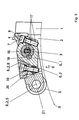
- the roller lever 6 is functionally configured in two parts according to the present invention (Fig. 1,2).
- a first part 6.1 is non-rotatably on one side by means of clamp 17 and feather key 18 the gripper shaft 3 fixed and thus pivotable together with this.
- a second part of the Roller lever 6.2 consists of two parallel webs 6.2.S, approximately in the middle (Fig.2) by one Bridge 6.2.B are connected.
- the webs 6.2.S are the first roller lever part 6.1 on both sides to and in each case by means of annular clamps 6.2.K non-positively arranged on the gripper shaft 3.
- On the opposite side, projecting beyond the first part 6.1, is between the cam roller 5 is mounted on both webs 6.2.
- a connecting element 19 on the The end face of the gripper shaft 3 serves to transmit torque from the torsion bar spring 16 on the second roller lever part 6.2.
- the connecting element 19 is form-fitting with the Torsion bar spring 16 connected and with the outer web 6.2.S of the second roller lever part 6.2 screwed.
- the first part of the roller lever 6.1 lies flat on the bridge 6.2.B of the second, longer one Part 6.2 of the roller lever 6 and is by a screw 10 with the bridge 6.2.B connected.
- the screw connection 10 consists of an oscillating in the bridge 6.2.B stored threaded bolt, which is arranged in a in the first roller lever part 6.1 Pendulum pin engages with internal thread.
- the torque of the torsion bar spring 16 is thus via the front connecting element 19 to the second roller lever part 6.2, from this via the screw 10 on the bridge 6.2.B to the first roller lever part 6.1 and from there to the gripper shaft 3.
- a lockable pinion 13 engages, which are each mounted on the bridge of the second roller lever part 6.2.
- the pinion 13 can be manually e.g. via a form-fitting attack on the pinion shaft Tool can be rotated and by a locking screw arranged on the pinion shaft 14 be fixed in its opening angle position.
- a fourth variant of the split roller lever (Fig.5) is the underside of the bridge 6.2.B the first variant of the roller lever from Figure 1 executed as a slope, the vertical Angle to the longitudinal axis 21 of the roller lever 6 is dimensioned so that a straight distance gauge from the outside above the cam roller 5 between bridge 6.2.B and top of the first roller lever part 6.1 can be inserted.
- both roller lever parts 6.1.6.2 with the help of the respective connecting elements 10 or 11, 12 or 11, 13, 14 in their starting position brought, secured with the additional locking screw 15 (variant 2 and 3) and finally the terminals 6.2.K closed.
- the clamps on the gripper shaft 3 on the second part of the roller lever 6.2 must first be released.
- the opening angle of the gripper tongues 7 is only determined by the position of the first roller lever part 6.1.
- the screw connection 10 is opened manually and, with further rotation of the screw connection 10, the opening angle between the longitudinal axes of the roller lever parts 6. 1, 6. 2 is enlarged and the gripper shaft 3 is rotated, so that the gripper tongues 7 lift off the gripper cuffs 8.
- a distance gauge the thickness of which corresponds to the desired “overpressure”, ie the deflection of the gripper tongues 7 from their normal position on the gripper shaft 3 when closing, and thus represents a measure of the pressing force of the gripper tongues 7, between the adjusting surface 20 of the bridge 6.2.B and inserted the first roller lever part 6.1.
- the connection between the two roller lever parts 6.1.6.2 is closed again, the distance gauge remaining in the gap between the two roller lever parts 6.1.6.2.
- the grippers 4 need only be individually adjusted on the gripper shaft 3 so that their gripper tongues 7 lie evenly on the gripper cuffs 8. No further adjustments are required.
Landscapes
- Supply, Installation And Extraction Of Printed Sheets Or Plates (AREA)
Applications Claiming Priority (4)
| Application Number | Priority Date | Filing Date | Title |
|---|---|---|---|
| DE19956369 | 1999-11-24 | ||
| DE19956369A DE19956369A1 (de) | 2000-04-15 | 1999-11-24 | Rollenhebel in Greifersteuergetrieben an bogenführenden Zylindern in Bogenrotationsdruckmaschinen |
| DE10018830 | 2000-04-15 | ||
| DE10018830A DE10018830A1 (de) | 1999-11-24 | 2000-04-15 | Rollenhebel zur Steuerung von Greifern |
Publications (2)
| Publication Number | Publication Date |
|---|---|
| EP1103376A1 true EP1103376A1 (fr) | 2001-05-30 |
| EP1103376B1 EP1103376B1 (fr) | 2002-06-19 |
Family
ID=26005334
Family Applications (1)
| Application Number | Title | Priority Date | Filing Date |
|---|---|---|---|
| EP00124593A Expired - Lifetime EP1103376B1 (fr) | 1999-11-24 | 2000-11-10 | Levier à galets dans des mécanismes de commande de pinces dans des cylindres de transport de feuilles dans des presses rotatives d'impression |
Country Status (3)
| Country | Link |
|---|---|
| EP (1) | EP1103376B1 (fr) |
| AT (1) | ATE219421T1 (fr) |
| DE (1) | DE10018830A1 (fr) |
Families Citing this family (1)
| Publication number | Priority date | Publication date | Assignee | Title |
|---|---|---|---|---|
| DE10248974B4 (de) * | 2001-11-16 | 2019-01-24 | Heidelberger Druckmaschinen Ag | Greiferanordnung in einer Rotationsdruckmaschine |
Citations (4)
| Publication number | Priority date | Publication date | Assignee | Title |
|---|---|---|---|---|
| US2599776A (en) * | 1947-05-24 | 1952-06-10 | Miehle Printing Press & Mfg | Sheet gripper structure and setting means therefor |
| EP0152553A2 (fr) * | 1984-02-18 | 1985-08-28 | M.A.N.-ROLAND Druckmaschinen Aktiengesellschaft | Pince de feuille pour machine à imprimer |
| EP0194549A2 (fr) * | 1985-03-12 | 1986-09-17 | M.A.N.-ROLAND Druckmaschinen Aktiengesellschaft | Dispositif de commande pour les pinces dans une rotative à feuilles |
| DE4028367A1 (de) * | 1990-09-07 | 1992-03-12 | Planeta Druckmaschinenwerk Ag | Bogenfuehrungseinrichtung in bogenbe- und verarbeitenden maschinen |
-
2000
- 2000-04-15 DE DE10018830A patent/DE10018830A1/de not_active Withdrawn
- 2000-11-10 EP EP00124593A patent/EP1103376B1/fr not_active Expired - Lifetime
- 2000-11-10 AT AT00124593T patent/ATE219421T1/de not_active IP Right Cessation
Patent Citations (4)
| Publication number | Priority date | Publication date | Assignee | Title |
|---|---|---|---|---|
| US2599776A (en) * | 1947-05-24 | 1952-06-10 | Miehle Printing Press & Mfg | Sheet gripper structure and setting means therefor |
| EP0152553A2 (fr) * | 1984-02-18 | 1985-08-28 | M.A.N.-ROLAND Druckmaschinen Aktiengesellschaft | Pince de feuille pour machine à imprimer |
| EP0194549A2 (fr) * | 1985-03-12 | 1986-09-17 | M.A.N.-ROLAND Druckmaschinen Aktiengesellschaft | Dispositif de commande pour les pinces dans une rotative à feuilles |
| DE4028367A1 (de) * | 1990-09-07 | 1992-03-12 | Planeta Druckmaschinenwerk Ag | Bogenfuehrungseinrichtung in bogenbe- und verarbeitenden maschinen |
Also Published As
| Publication number | Publication date |
|---|---|
| EP1103376B1 (fr) | 2002-06-19 |
| ATE219421T1 (de) | 2002-07-15 |
| DE10018830A1 (de) | 2001-10-31 |
Similar Documents
| Publication | Publication Date | Title |
|---|---|---|
| EP0170111B1 (fr) | Tambour de transfert pour machine à imprimer des feuilles, en particulier pour machines de cartonnerie | |
| DE3112964C2 (fr) | ||
| DE3644484A1 (de) | Greifereinrichtung fuer eine druckmaschine | |
| EP0523367A1 (fr) | Cylindre de guidage du papier dans des machines rotatives à imprimer des feuilles | |
| DE8816641U1 (de) | Vorrichtung zur Passerkorrektur der Bogenaufdrucke in einer Bogenrotationsdruckmaschine | |
| DE3123990A1 (de) | Einstellvorrichtung fuer farb- u. feuchtwalzen an druckmaschinen | |
| EP1103376B1 (fr) | Levier à galets dans des mécanismes de commande de pinces dans des cylindres de transport de feuilles dans des presses rotatives d'impression | |
| CH628285A5 (en) | Sheet-holding device of a sheet-fed rotary printing machine which is capable of slightly deforming the printing sheet | |
| DD258211A1 (de) | Einrichtung zum steuern der greifer eines vorgreifers in bogenverarbeitenden maschinen | |
| EP0374496B1 (fr) | Positionneurs pour les bords avant de feuilles | |
| EP0648700B1 (fr) | Dispositif de réglage de la came d'ouverture des pinces d'une sortie à chaînes d'une machine à imprimer pour feuilles | |
| DE19611124B4 (de) | Bogenübertragungseinrichtung einer Bogenrotationsdruckmaschine | |
| DE10248974A1 (de) | Greiferanordnung in einer Rotationsdruckmaschine | |
| DE102009001190B4 (de) | Bogenverarbeitende Maschine mit einem Anlegetisch | |
| DE19956369A1 (de) | Rollenhebel in Greifersteuergetrieben an bogenführenden Zylindern in Bogenrotationsdruckmaschinen | |
| DE102007005958B4 (de) | Vorrichtung zum Bogentransport | |
| EP1818300B1 (fr) | Dispositif de pliage transversal d'un appareil de pliage d'une presse | |
| DE102005016321B3 (de) | Lackierwerk | |
| DE19538322C2 (de) | Einrichtung zur axialen Verstellung von Leitelementen | |
| DE4013261C1 (fr) | ||
| DE102011080194B4 (de) | Bogenverarbeitende Maschine mit Bogengreifersystemen | |
| DE3220530C2 (de) | Vorrichtung zum Aufspannen von Tiefdruckplatten | |
| DE4037305C2 (de) | Einrichtung an Übergabetrommeln | |
| DE10149821B4 (de) | Einrichtung zum Steuern der Greifer eines Vorgreifers | |
| DE10225503B4 (de) | Zangengreifersystem in Wendetrommeln von Druckmaschinen |
Legal Events
| Date | Code | Title | Description |
|---|---|---|---|
| PUAI | Public reference made under article 153(3) epc to a published international application that has entered the european phase |
Free format text: ORIGINAL CODE: 0009012 |
|
| 17P | Request for examination filed |
Effective date: 20010329 |
|
| AK | Designated contracting states |
Kind code of ref document: A1 Designated state(s): AT BE CH CY DE DK ES FI FR GB GR IE IT LI LU MC NL PT SE TR |
|
| AX | Request for extension of the european patent |
Free format text: AL;LT;LV;MK;RO;SI |
|
| GRAG | Despatch of communication of intention to grant |
Free format text: ORIGINAL CODE: EPIDOS AGRA |
|
| GRAG | Despatch of communication of intention to grant |
Free format text: ORIGINAL CODE: EPIDOS AGRA |
|
| GRAH | Despatch of communication of intention to grant a patent |
Free format text: ORIGINAL CODE: EPIDOS IGRA |
|
| 17Q | First examination report despatched |
Effective date: 20011129 |
|
| GRAH | Despatch of communication of intention to grant a patent |
Free format text: ORIGINAL CODE: EPIDOS IGRA |
|
| AKX | Designation fees paid |
Free format text: AT BE CH CY DE DK ES FI FR GB GR IE IT LI LU MC NL PT SE TR |
|
| GRAA | (expected) grant |
Free format text: ORIGINAL CODE: 0009210 |
|
| AK | Designated contracting states |
Kind code of ref document: B1 Designated state(s): AT BE CH CY DE DK ES FI FR GB GR IE IT LI LU MC NL PT SE TR |
|
| PG25 | Lapsed in a contracting state [announced via postgrant information from national office to epo] |
Ref country code: FI Free format text: LAPSE BECAUSE OF FAILURE TO SUBMIT A TRANSLATION OF THE DESCRIPTION OR TO PAY THE FEE WITHIN THE PRESCRIBED TIME-LIMIT Effective date: 20020619 Ref country code: GR Free format text: LAPSE BECAUSE OF FAILURE TO SUBMIT A TRANSLATION OF THE DESCRIPTION OR TO PAY THE FEE WITHIN THE PRESCRIBED TIME-LIMIT Effective date: 20020619 Ref country code: IE Free format text: LAPSE BECAUSE OF FAILURE TO SUBMIT A TRANSLATION OF THE DESCRIPTION OR TO PAY THE FEE WITHIN THE PRESCRIBED TIME-LIMIT Effective date: 20020619 Ref country code: TR Free format text: LAPSE BECAUSE OF FAILURE TO SUBMIT A TRANSLATION OF THE DESCRIPTION OR TO PAY THE FEE WITHIN THE PRESCRIBED TIME-LIMIT Effective date: 20020619 Ref country code: NL Free format text: LAPSE BECAUSE OF FAILURE TO SUBMIT A TRANSLATION OF THE DESCRIPTION OR TO PAY THE FEE WITHIN THE PRESCRIBED TIME-LIMIT Effective date: 20020619 |
|
| REF | Corresponds to: |
Ref document number: 219421 Country of ref document: AT Date of ref document: 20020715 Kind code of ref document: T |
|
| REG | Reference to a national code |
Ref country code: GB Ref legal event code: FG4D Free format text: NOT ENGLISH |
|
| REG | Reference to a national code |
Ref country code: CH Ref legal event code: EP |
|
| REG | Reference to a national code |
Ref country code: IE Ref legal event code: FG4D Free format text: GERMAN |
|
| REF | Corresponds to: |
Ref document number: 50000227 Country of ref document: DE Date of ref document: 20020725 |
|
| PG25 | Lapsed in a contracting state [announced via postgrant information from national office to epo] |
Ref country code: SE Free format text: LAPSE BECAUSE OF FAILURE TO SUBMIT A TRANSLATION OF THE DESCRIPTION OR TO PAY THE FEE WITHIN THE PRESCRIBED TIME-LIMIT Effective date: 20020919 Ref country code: DK Free format text: LAPSE BECAUSE OF FAILURE TO SUBMIT A TRANSLATION OF THE DESCRIPTION OR TO PAY THE FEE WITHIN THE PRESCRIBED TIME-LIMIT Effective date: 20020919 |
|
| PG25 | Lapsed in a contracting state [announced via postgrant information from national office to epo] |
Ref country code: PT Free format text: LAPSE BECAUSE OF FAILURE TO SUBMIT A TRANSLATION OF THE DESCRIPTION OR TO PAY THE FEE WITHIN THE PRESCRIBED TIME-LIMIT Effective date: 20020923 |
|
| GBT | Gb: translation of ep patent filed (gb section 77(6)(a)/1977) |
Effective date: 20020917 |
|
| PG25 | Lapsed in a contracting state [announced via postgrant information from national office to epo] |
Ref country code: AT Free format text: LAPSE BECAUSE OF NON-PAYMENT OF DUE FEES Effective date: 20021110 Ref country code: LU Free format text: LAPSE BECAUSE OF NON-PAYMENT OF DUE FEES Effective date: 20021110 |
|
| ET | Fr: translation filed | ||
| PG25 | Lapsed in a contracting state [announced via postgrant information from national office to epo] |
Ref country code: BE Free format text: LAPSE BECAUSE OF NON-PAYMENT OF DUE FEES Effective date: 20021130 Ref country code: CY Free format text: LAPSE BECAUSE OF FAILURE TO SUBMIT A TRANSLATION OF THE DESCRIPTION OR TO PAY THE FEE WITHIN THE PRESCRIBED TIME-LIMIT Effective date: 20021130 |
|
| NLV1 | Nl: lapsed or annulled due to failure to fulfill the requirements of art. 29p and 29m of the patents act | ||
| PG25 | Lapsed in a contracting state [announced via postgrant information from national office to epo] |
Ref country code: ES Free format text: LAPSE BECAUSE OF FAILURE TO SUBMIT A TRANSLATION OF THE DESCRIPTION OR TO PAY THE FEE WITHIN THE PRESCRIBED TIME-LIMIT Effective date: 20021220 |
|
| REG | Reference to a national code |
Ref country code: IE Ref legal event code: FD4D Ref document number: 1103376E Country of ref document: IE |
|
| PLBE | No opposition filed within time limit |
Free format text: ORIGINAL CODE: 0009261 |
|
| STAA | Information on the status of an ep patent application or granted ep patent |
Free format text: STATUS: NO OPPOSITION FILED WITHIN TIME LIMIT |
|
| BERE | Be: lapsed |
Owner name: *KOENIG & BAUER A.G. Effective date: 20021130 |
|
| PG25 | Lapsed in a contracting state [announced via postgrant information from national office to epo] |
Ref country code: MC Free format text: LAPSE BECAUSE OF NON-PAYMENT OF DUE FEES Effective date: 20030601 |
|
| 26N | No opposition filed |
Effective date: 20030320 |
|
| PG25 | Lapsed in a contracting state [announced via postgrant information from national office to epo] |
Ref country code: LI Free format text: LAPSE BECAUSE OF NON-PAYMENT OF DUE FEES Effective date: 20041130 Ref country code: CH Free format text: LAPSE BECAUSE OF NON-PAYMENT OF DUE FEES Effective date: 20041130 |
|
| REG | Reference to a national code |
Ref country code: CH Ref legal event code: PL |
|
| PGFP | Annual fee paid to national office [announced via postgrant information from national office to epo] |
Ref country code: FR Payment date: 20101130 Year of fee payment: 11 |
|
| PGFP | Annual fee paid to national office [announced via postgrant information from national office to epo] |
Ref country code: DE Payment date: 20101122 Year of fee payment: 11 |
|
| PGFP | Annual fee paid to national office [announced via postgrant information from national office to epo] |
Ref country code: IT Payment date: 20101123 Year of fee payment: 11 Ref country code: GB Payment date: 20101118 Year of fee payment: 11 |
|
| GBPC | Gb: european patent ceased through non-payment of renewal fee |
Effective date: 20111110 |
|
| REG | Reference to a national code |
Ref country code: FR Ref legal event code: ST Effective date: 20120731 |
|
| PG25 | Lapsed in a contracting state [announced via postgrant information from national office to epo] |
Ref country code: IT Free format text: LAPSE BECAUSE OF NON-PAYMENT OF DUE FEES Effective date: 20111110 |
|
| REG | Reference to a national code |
Ref country code: DE Ref legal event code: R119 Ref document number: 50000227 Country of ref document: DE Effective date: 20120601 |
|
| PG25 | Lapsed in a contracting state [announced via postgrant information from national office to epo] |
Ref country code: GB Free format text: LAPSE BECAUSE OF NON-PAYMENT OF DUE FEES Effective date: 20111110 |
|
| PG25 | Lapsed in a contracting state [announced via postgrant information from national office to epo] |
Ref country code: FR Free format text: LAPSE BECAUSE OF NON-PAYMENT OF DUE FEES Effective date: 20111130 |
|
| PG25 | Lapsed in a contracting state [announced via postgrant information from national office to epo] |
Ref country code: DE Free format text: LAPSE BECAUSE OF NON-PAYMENT OF DUE FEES Effective date: 20120601 |