EP1103379A1 - Verfahren und Vorrichtung von gesteuerten RF-Schaltverhältnissen, um thermische Gleichmässigkeit im akustischen Brennpunkt eienes akustischen Tintendruckkopfes zu erreichen - Google Patents
Verfahren und Vorrichtung von gesteuerten RF-Schaltverhältnissen, um thermische Gleichmässigkeit im akustischen Brennpunkt eienes akustischen Tintendruckkopfes zu erreichen Download PDFInfo
- Publication number
- EP1103379A1 EP1103379A1 EP00125040A EP00125040A EP1103379A1 EP 1103379 A1 EP1103379 A1 EP 1103379A1 EP 00125040 A EP00125040 A EP 00125040A EP 00125040 A EP00125040 A EP 00125040A EP 1103379 A1 EP1103379 A1 EP 1103379A1
- Authority
- EP
- European Patent Office
- Prior art keywords
- drop
- column
- row
- compensation
- switching ratio
- Prior art date
- Legal status (The legal status is an assumption and is not a legal conclusion. Google has not performed a legal analysis and makes no representation as to the accuracy of the status listed.)
- Granted
Links
- 238000000034 method Methods 0.000 title description 3
- 239000011159 matrix material Substances 0.000 claims abstract description 39
- 239000007788 liquid Substances 0.000 claims description 9
- 239000003990 capacitor Substances 0.000 description 27
- 239000000976 ink Substances 0.000 description 24
- 230000003071 parasitic effect Effects 0.000 description 7
- 239000004020 conductor Substances 0.000 description 6
- 230000008859 change Effects 0.000 description 5
- 238000013459 approach Methods 0.000 description 4
- 230000015556 catabolic process Effects 0.000 description 4
- 238000006731 degradation reaction Methods 0.000 description 4
- 238000010438 heat treatment Methods 0.000 description 4
- 230000008878 coupling Effects 0.000 description 3
- 238000010168 coupling process Methods 0.000 description 3
- 238000005859 coupling reaction Methods 0.000 description 3
- 238000010304 firing Methods 0.000 description 3
- 230000006872 improvement Effects 0.000 description 3
- 230000008901 benefit Effects 0.000 description 2
- 230000001419 dependent effect Effects 0.000 description 2
- 230000008569 process Effects 0.000 description 2
- 230000005855 radiation Effects 0.000 description 2
- 230000001154 acute effect Effects 0.000 description 1
- 230000009286 beneficial effect Effects 0.000 description 1
- 230000001186 cumulative effect Effects 0.000 description 1
- 230000003247 decreasing effect Effects 0.000 description 1
- 238000010586 diagram Methods 0.000 description 1
- 230000009977 dual effect Effects 0.000 description 1
- 239000000284 extract Substances 0.000 description 1
- 230000017525 heat dissipation Effects 0.000 description 1
- 230000021715 photosynthesis, light harvesting Effects 0.000 description 1
- 230000009467 reduction Effects 0.000 description 1
- 238000012163 sequencing technique Methods 0.000 description 1
- 230000003068 static effect Effects 0.000 description 1
Images










Classifications
-
- B—PERFORMING OPERATIONS; TRANSPORTING
- B41—PRINTING; LINING MACHINES; TYPEWRITERS; STAMPS
- B41J—TYPEWRITERS; SELECTIVE PRINTING MECHANISMS, i.e. MECHANISMS PRINTING OTHERWISE THAN FROM A FORME; CORRECTION OF TYPOGRAPHICAL ERRORS
- B41J2/00—Typewriters or selective printing mechanisms characterised by the printing or marking process for which they are designed
- B41J2/005—Typewriters or selective printing mechanisms characterised by the printing or marking process for which they are designed characterised by bringing liquid or particles selectively into contact with a printing material
- B41J2/01—Ink jet
- B41J2/135—Nozzles
- B41J2/14—Structure thereof only for on-demand ink jet heads
- B41J2/14008—Structure of acoustic ink jet print heads
Definitions
- the present invention relates to acoustic printing, and more particularly to controlling the on/off switching ratio between ejectors of an acoustic printhead.
- an array of ejectors forming a printhead is covered by a pool of liquid.
- Each ejector can direct a beam of sound energy against a free surface of the liquid.
- the impinging acoustic beam exerts radiation pressure against the surface of the liquid.
- the ejectors may be arranged in a matrix or array of rows and columns, where the rows stretch across the width of the recording medium, and the columns of ejectors are approximately perpendicular.
- each ejector when activated ejects a droplet identical in size to the droplets of all the other ejectors in the array.
- each ejector should operate under identical conditions.
- the general practice is to address individual ejectors by applying a common RF pulse to a segment of a row, and to control the current flow to each ejector using column switches.
- this approach results in parasitic current paths which can cause undesired RF current to flow through ejectors that are not in an ON state.
- a switching ratio is defined as the RF power in an OFF ejector to the RF power in an ON ejector (i.e. P OFF /P ON ).
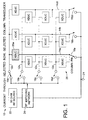
- FIGURE 1 illustrates an acoustic switching array with a desired current path for a selected row and selected column for an existing system.
- Switching matrix 10 is a 4-row 12a , 12b , 12c , 12d by 64 column 14a , 14b , 14zz switching matrix. Rows are connected to the matrix via switching elements 16a , 16b , 16c , 16d , and columns are connected through switching elements 18a , 18b , 18zz . At the intersection of the columns and rows are transducers 20 . Current paths of matrix 10 are terminated at RF ground 21 . It is to be appreciated that while the matrix of FIGURE 1 is a 4-row by 64-column matrix, the present invention may be used in other matrix designs.
- Matrix 10 is supplied by a power source 22 which provides its output to an RF signal matching circuit 24 .
- a desired current path for a selected row and selected column is obtained. For example, in FIGURE 1, by closing switch 16a and switch 18a , a current path is provided from the RF matching network 24 to transducer 20a via row 12a and column 14a . As the remaining rows and columns are unselected, only transducer 20a is intended to be activated to emit a droplet.
- interconnect paths used to implement a low cost acoustic printhead include unavoidable, undesirable current paths, as shown and discussed for example, in connection with FIGURES 2-4.
- FIGURE 2 is a simplified depiction of an undesired current path through an unselected transducer in the same row as a selected transducer.
- switches 16a and 18a are maintained in a closed position while the remaining switches are unselected. Therefore current is provided to transducer 20a .
- undesired current will also flow through transducer 20b , which is in selected row 12a but unselected column 14b .
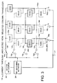
- FIGURE 3 illustrates a situation where an undesired current flows through transducer 20c, which is in selected column 14a and unselected row 12c .
- Column switches 18a - 18zz are, in one embodiment, implemented with a component such as a PIN diode, which has a reasonably high intrinsic switching ratio, i.e., in the range of -6dB or greater.
- a high switching ratio of this type may insure that a particular column switch is securely turned OFF if it were the only device in the system.
- a net switching ratio of a selected column and a selected row ejector can vary between approximately -2.3dB and -6dB, depending upon the number of existing parasitic current paths through ejectors which are not selected.
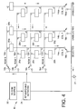
- FIGURE 4 a more detailed discussion is provided regarding the parasitic current paths introduced in connection with FIGURES 2 and 3.
- the transducers are identified by the row and column numbers to which they are connected. For the case illustrated, all current paths start from the conductor of row0, 12a , and terminate at RF ground return 21 .
- transducer 20b is an unselected transducer.
- the undesired current through unselected transducer 20b consists of three components, all of which start from row0, 12a , and proceed down through transducer 20b .
- the first component flows from transducer 20b , down through the top segment of column1, 14b , up through transducer 20d , through a segment of row1, 12b , down through transducer 20e , down through column0, 14a , and finally through the selected column0 switch, 18a , to RF ground return 21 .
- the path of the second component is from row0, 12a , down through transducer 20b , and the top two segments of column1, 14b , up through transducer 20f , through a segment of row2, 12c , down through transducer 20c , down through columnO, 14a , and finally through columnO switch , 18a , to RF ground return 21 .
- the path of the third component is from row0, 12a , down through transducer 20b , and the top three segments of column1, 14b , up through transducer 20g , through a segment of row3, 12d , down through transducer 20h , down through column0, 14a , and finally through columnO switch 18a , to RF ground return 21 .
- Unwanted current paths similar to those just described, also exist through other unselected transducers located on row0, 12a , and columns 2 through 63 ( 14b - 14zz ).
- Transducers 20e , 20c , and 20h have the largest magnitude of total unwanted current.
- the current flowing through the unselected transducer 20e is the sum of the currents in all the other transducers in rowl, 12b . All of this unwanted current flows through the conducting path of unselected rowl, 12b .
- transducers 20e , 20c and 20h are on a selected column and unselected rows. The switching ratio is the poorest for this category when only one column is selected. This may also be seen in FIGURES 6 and 7.
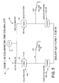
- FIGURES 5, 6, 9, 10, 15, 16 and 18 are block diagrams representing four categories of transducer states used in calculations of relative RF currents to determine the switching ratios for different numbers of selected columns.
- the block in the upper left part of the figure represents all of the transducers that are at Selected Row, Selected Column locations.
- the block in the upper right part of the figure represents all of the transducers that are at Selected Row, Unselected Column locations.
- the block in the lower left part of the figure represents all of the transducers that are at Unselected Row, Selected column locations, and the block in the lower right part of the figure represents all of the transducers that are at Unselected Row, Unselected Column locations.
- FIGURE 5 illustrates a situation where 63 columns 26 , and one row 12a are selected, ON, and a single column 28 and remaining three rows 12b-12d are unselected, or OFF.
- the inventors have calculated that there is approximately 514 ⁇ A flowing through each of the 63 transducers 30 , which represents the transducers in selected row 12a , and 63 ON columns 26 of matrix 10 .
- FIGURE 6 depicts an alternative arrangement where one column 34 , and one row 12a are selected, and remaining 63 columns 36 and 3 rows 12b - 12d are unselected.
- the selected current path for transducer 38 has a current of 504 ⁇ A, whereas an unwanted current of approximately 368 ⁇ A exists through each of the unselected transducers connected to selected column 34 and unselected rows 12b - 12d .
- the cumulative current through switch 18a is approximately 1607 ⁇ A (i.e. 504 ⁇ A from the selected transducer in column 34 , row 12a and 368uA from each of the three unselected transducers on column 34 , on rows 12b - 12d ).
- FIGURE 7 summarizes the effective switching ratios relative to selected row/unselected columns, and selected columns/unselected rows as a function of the number of ejectors in the row which are ON.
- curve 40 shows that as the number of selected columns increase, for an unselected row, the relative switching ratio improves substantially, i.e. approximately to -10dB at 20 columns selected.
- curve 42 illustrates that for a selected row, as additional columns are moved to an ON state, the switching ratio is degraded substantially, i.e. from about -11 dB at one column ON, to about -2.5dB for 63 columns ON.
- the desired ejection velocity will be approximately 4 m/sec. This can be achieved using approximately 1dB of power over the ejection threshold. Given that there are ejection threshold power non-uniformities in the aqueous printhead of approximately +/- 0.5dB, and the desire to maintain some margin of safety (e.g.
- switching ratio (SR) ⁇ overdrive for 4 m/sec
- SR ⁇ non-uniformity
- a switching ratio of -2.5 to -3.0dB will be acceptable for printing of aqueous inks, when a -.5 to -1.0dB safety margin is added.
- phase-change inks require more power over the threshold than aqueous inks.
- a -4dB power over the threshold will be required.
- phase-change inks it is intended to use static E-fields to reduce this power requirement, however it is still necessary to eject the droplets at approximately 2m/sec, i.e. -2dB over threshold.
- a further complication which exists for phase-change printing is that thermal uniformity requirements are more exacting than for aqueous printing because the acoustic losses in the ink are larger, and phase-change inks change more strongly with temperature than aqueous inks.
- a several degrees celsius change across the printhead, or between the ON and OFF states of a given ejector can result in spatial and time-varying non-uniformities which will degrade output.
- a 1-2C° change can result in a degradation in the drop diameter uniformity of 1-3%. It is believed the upper limit on drop diameter non-uniformity that can be tolerated for acceptable print quality is only 5%. Thus even comparatively small changes in temperature will cause printing degradation.
- the foregoing problem is particularly acute for low flow printheads, i.e. printheads where the ink is not quickly passed through the printhead.
- the acoustic energy will raise the temperature of the focal region above the bulk of the ink.
- the temperature rise has been determined to be as much as 12°C. While this temperature rise can be used to an advantage (i.e. reducing the temperature requirement for the bulk volume of the ink in the printhead), it poses a problem of non-equal thermal environments for ejectors that are ON versus those that are OFF.
- An acoustic printhead includes a matrix of drop ejectors configured in rows and columns.
- Each drop ejector includes at least a transducer and a switch. When a particular drop ejector is selected, the associated transducer and switch are turned on, and the transducer functions so as to cause the particular drop ejector to eject a drop from a pool of liquid. When the particular drop ejector is not selected, the associated transducer and switch are off, and the particular drop ejector does not eject a drop from the pool of liquid.
- a plurality of row switches, connected to control operation of the rows of drop ejectors are provided.
- a plurality of column switches connected to control operation of the columns of drop ejectors, wherein by selection of an appropriate row switch and column switch, the particular transducer of a specific drop ejector is turned on.
- a controller connected to the plurality of row switches and the plurality of column switches acts to control selection of the drop ejectors.
- a compensation network connected to at least one of the rows of drop ejectors and columns of drop ejectors, wherein the compensation network selectively provides compensation energy to drop ejectors which are not selected, to lower undesirable current flow.
- the compensation network may be configured to control a switching ratio of the matrix of drop ejectors, where the switching ratio is defined as the amount of power in a drop ejector which is off compared to the amount of power in a drop ejector which is on, and wherein control of the switching ratio includes improving the switching ratio of the acoustic printhead for a four-row, 64-column drop ejector array to at least -5 dB.
- a switching ratio is selected to balance power differences between on/off drop ejectors, against the thermal energy which is carried away by the ejected drop.
- a general practice for controlling the emitters of an acoustic ink printer array is to address the individual ejectors by applying a common RF pulse to a segment of a row, and to control the current flow to each ejector using column switches.
- the present invention describes a scheme and accompanying architectures which are able to maintain a precise switching ratio, independent of the number of ejectors ON, in order to limit thermal non-uniformities in printheads.
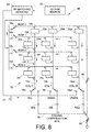
- FIGURE 8 illustrates a transducer matrix 60 , to assist in the description of the concept of providing a compensating current path to the column nodes of the transducer matrix as used in acoustic printheads Providing compensation results in a smaller amount of undesirable current flow, allowing for an improvement in the switching ratio which has been defined as the ratio of the undesired RF power in an OFF ejector to the RF power in an ejector that is in an ON state (i.e. P OFF / P ON ).
- the 4 row by 64 column transducer array 60 depicted in FIGURE 8 is substantially similar in part to the configuration shown in FIGURES 4 -6.
- column0, 14a is selected, and all other columns are not selected.
- the troublesome current paths are those that flow through unselected transducers 20e , 20c and 20h , where the switching ratio is -2.73 dB, as calculated in FIGURE 6.
- These currents originate on selected row0, 12a , and flow through unselected transducers 20b --- 20zz , to the unselected column conductors, for columns 14b through 14zz .
- the unwanted currents then flow from the unselected columns, through three groups of transducers to the three unselected row conductors.
- transducers 20c , 20c and 20h The path is completed through transducers 20c , 20c and 20h and the selected columnO, 14a , column conductor and column switch 18a , to a ground return 21 .
- the switching ratio for transducers 20e , 20c and 20h can be improved to be better than -5 dB by adding a compensation current path from the unselected column conductors to ground return 21 .
- FIGURE 8 One way to accomplish this is shown in FIGURE 8.
- the column switches ( 18a - 18zz ) are changed from Single-Pole-Single-Throw to Single-Pole-Double-Throw.
- Small value compensation capacitors e.g. 1pF
- 52a - 52zz connect the new normally closed contact on each column switch to a column compensation bus 54 .
- the column compensation bus 54 extracts current from each of the unselected column conductors and passes it to ground return 21 , through a variable pull down capacitor 56 .
- the formed compensation current path will carry some of the current that would, in the absence of the compensation path, flow through the transducers 20e , 20c , 20h in the Selected-Column, Unselected-Row category, thereby reducing the magnitude of the unwanted current and improving the switching ratio.
- the value of a pull-up capacitor 58 is very small so only a negligible current will flow through it to the column compensation bus 54 .
- the uncompensated switching ratio for the 1 column off, 63 columns selected case is -2.32 dB as shown in FIGURE 5.
- the compensation path from selected row0, through pull-up capacitor 58 to the column compensation bus 54 is added (as depicted in FIGURE 8), the compensation path is able to carry some of the unwanted current that would otherwise flow through the Selected-Row, Unselected-Column transducer such that the switching ratio is improved to -5.67 dB, as shown in FIGURE 9.
- FIGURE 9 depicts a simplified version of a switching matrix 60 having 4 rows and 64 columns.
- switching matrix 60 has 63 selected columns 62 , and a single selected row 12a .
- This circuit also depicts a single unselected column 66 and 3 unselected rows 12b - 12d .
- a column switch 68 is in a selected position, which corresponds to the selection of the 63 columns 62 .
- Column switch 70 is in an unselected state.
- a compensation selection circuit 72 which includes a first capacitor 74 , which in this embodiment may be a 1 pico-farad capacitor, and switching terminals 76 , 78 and 80 .
- Terminal 78 has included therein a 32 pico-farad compensation capacitor 82
- terminal 80 has a 16 pico-farad compensation capacitor 84 .
- a compensation selector switch 86 when a compensation selector switch 86 is connected to terminal 76 , a connection is made from RF source 88 through capacitor 74 to switch 70 .
- this arrangement depicts an arrangement to provide a compensating current path to the column nodes of a transducer matrix used in acoustic printheads. Also, in FIGURE 8 choosing a large value capacitor, as the pull-up capacitor 58 , results in operational characteristics corresponding to having compensation selector switch 86 , connected to switching terminal 76 .
- compensation capacitor 90 is provided for connection to columns 1-63. It is to be appreciated that compensation capacitor 90 represents a network of compensation capacitors such that each column has appropriate capacitive values. Further, a column compensation bus 91, similar to column compensation bus 54 of FIGURE 8, is provided between compensation capacitor 90 and compensation selector switch 86 . Capacitors 74 and 90 provide current paths from the column compensation bus 91 to individual column switches, such as switch 70 .
- FIGURE 10 matrix configuration 60 of FIGURE 9 which shows an alternative view of the case dealt with in connection with FIGURE 8.
- a single column is selected 100 and 63 columns are unselected 102 .
- a single row is selected 12a and three rows of the matrix are unselected 12b - 12d .
- Compensation selection network 72 is shown with compensation selector 86 connected to terminal 80 , which includes compensation capacitor 84 coupled to ground.
- the switching network 10 of FIGURE 5 (which includes 63 selected columns and one selected row) has a switching ratio of -2.32dB
- the addition and use of compensation selection network 72 of FIGURE 9 is able to improve this switching ratio to - 5.67dB.
- the switching network of FIGURE 6 (which includes one selected column and one selected row) has a switching ratio of -2.73dB
- compensation selection network 72 of FIGURE 10 improves its switching ratio to -5.04dB.
- the foregoing discussion illustrates the addition of a compensation selection network 72 allows for an improvement in the switching ratio for ejectors of an acoustic ink printer.
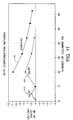
- FIGURE 11 shows the switching ratio characteristics of the compensation selection network 72 for a matrix 60 as shown in the forgoing figures.
- Curve 110 depicts a switching ratio achievable when compensation selector switch 86 is connected to terminal 80 .
- switch 70 is compensated by capacitive coupling to ground, through capacitors 74 and 84 .
- the switching ratio first improves from approximately -5dB to a best value of approximately -6dB, and then begins to degrade below a -5dB switching ratio.
- Curve 112 shows the characteristics of operation when compensation selector 86 is connected to terminal 78 , whereby the compensation current is provided from the RF switch source 88 through coupling capacitor 82 and capacitor 74 .
- Curve 112 shows an improvement in the switching ratio from approximately 10 columns ON to approximately 20 columns ON, and thereafter an inferior ON/OFF ratio in decibels, as additional columns are selected.
- curve 114 illustrates the switching ratio characteristics when compensation selector switch 86 is connected to terminal 76 such that the RF source 88 is directly connected to the column compensation bus 91 . While the switching ratio under this connection scheme is good at a lower number of selected columns, as the number of selected columns increase the switching ratio degrades. Additionally, as previously mentioned, selection of a large value capacitor as pull-up capacitor 58 , in FIGURE 8, results in the same operational characteristics obtained by having compensation selector switch 86 connected to switching terminal 76 of FIGURE 9.
- FIGURE 11 therefore, shows the switching ratios that can be achieved with different sources driving the column compensation bus and coupling capacitor 74 . It may be understood by reviewing FIGURE 11 that by having a selection of compensation options (i.e. 5 pico-farads to RF, 7 pico-farads to RF, 9 pico-farads to RF, etc.), it is possible to establish and maintain a switching ratio within a desired range, independent of the ratio of ON to OFF ejectors. It is also noted that it is necessary to take into consideration the characteristics of both transducers on the same column and transducers on the same row in order to maintain the switching ratio within a selected range over the entirety of the columns of the print head.
- compensation options i.e. 5 pico-farads to RF, 7 pico-farads to RF, 9 pico-farads to RF, etc.
- the compensation current is dynamically set to the proper values as image data changes.
- a raised temperature at this location can be used to an advantage as a means to locally reduce the viscosity at the point of ejection, decreasing the required ejection energy, and increasing the maximum firing rate. While this temperature rise can be advantageous, the exact value of the ejection temperature will depend upon the acoustic power level being supplied to a particular transducer. As a result, ejectors which are ON (i.e. at a power level P ON ), will have a different acoustic focal temperature than those which are OFF (i.e. at a power level P OFF ). Since the focal heat spot equilibrates in temperature much more slowly than the ejection rate, this can lead to uncontrolled, data-dependent changes in the acoustic ejection process, giving rise to print quality degradation.
- the temperature rise shown in FIGURE 12, approximately 10°C, is large enough to induce severe print non-uniformities. It was previously noted that a 1-2-degree C change in temperature can result in an increase in drop diameter non-uniformity of 1-3%. To avoid print degradation, the physical energy and heat dissipation must be proximal to that of the ink drop being expelled.
- an acoustic printhead 120 is designed such that acoustic energy 121 , generated by well known means, is focused by a lens 122 , or other focusing device, to a focal point 123 , which causes a pool of liquid 124 to expel a droplet 126 .
- the focal point 123 is located in close physical proximity to the printhead surface 128 .
- the detail of having a large amount of energy concentrated such that the heating of the printhead occurs near the ejected drop 126 means drop 126 will carry away a significant amount of heat energy. In this design, each droplet will carry away up to 50% or more of the heat at the focal point 123 .
- a further aspect of the present invention uses the dissipation of heat energy through expulsion of heated drop 126 , in combination with the controlling of the switching ratio, to provide a precisely controlled balance in the power difference against the thermal energy which is carried away by the ejected droplet.
- the heat of the drop is equal to the density multiplied by the volume of the drop multiplied by the specific heat, multiplied by the firing rate of an ejector.
- the region of concentrated heat for which there is most concern about maintaining uniform temperature between ON and OFF is immediately adjacent to the droplet which is carried away. Using this knowledge it is possible to select a specific switching ratio which will balance the ON and OFF states of the ejectors.
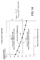
- FIGURE 14 shows two modeling results, one which includes the estimated heat temperature loss factor, and one without the inclusion of this heat temperature loss factor (this case is slightly different in detail than the values shown in FIGURE 12).
- Modeled curve 130 shows the focal heating region is approximately 30°C when the modeled temperature ON state does not take into consideration the thermal energy loss due to the ejected drop.
- Modeled curve 132 shows that the focal region temperature drops to slightly below 15°C, when the loss due to the ejection of the ejected drop is taken into consideration.
- the ejected drop is responsible for carrying away approximately 50% of the heat when the ejector is in an ON state.
- Curve 134 illustrates the temperature rise in the OFF state (i.e. when no droplet is ejected) is simply the upper ON state representation 130 , reduced by the amount of the switching ratio.
- Plotted in FIGURE 14 is the predicted OFF state temperature for a range of switching ratios -1 to -5dB.
- a switching ratio can be precisely chosen, as taught in FIGURES 9-11, such that the OFF-state temperature is equal to the ON-state temperature.
- the OFF ejector should have the exact same switching ratio relative to an ON ejector so a correct amount of power is being dissipated in the entire row.
- the OFF ejectors are supplied with sufficient compensation current to achieve this goal.
- FIGURE 15 depicts a 4-row, 64-column transducer switching matrix 160 which implements a row compensation network 162 according to the present invention.
- Row compensation is similar in function to column compensation in that adjustable compensation current paths are added around transducers that are located on unselected rows and/or columns, to modify the switching ratio as desired.
- the following example has one column ON 164 and 63 columns OFF 166 , with row 12 a selected while the remaining three rows 12b - 12d are unselected. It is to be appreciated the invention will of course work with other ON/OFF ratios.
- Row compensation network 162 includes a plurality of switches 168 , 170 , 172 and 174 , which may be selectively coupled to corresponding capacitive elements 176 , 178 , 180 and 182 .
- switches 168 - 174 By selectively controlling operation of switches 168 - 174 , it is possible to create a reasonably smooth profile of switching ratios by using different combinations of capacitors 176 - 182 to compensate unselected transducer rows.
- the row compensation design will add compensation current paths to the transducers on unselected rows. The paths are to the RF source or to ground return in a manner similar to that shown for column compensation in FIGURE 8.
- switches 172 and 174 are closed to incorporate capacitors 180 and 182 into the switching network, and switches 168 and 170 are not selected. By this arrangement, compensation is provided to the unselected rows 12b-12d to obtain a desired switching ratio.
- FIGURE 15 has illustrated the concepts of the present embodiment with a single ON column and 63 columns OFF, the invention is intended to work with other ON/OFF ratios as well as with a matrix having more than 64 columns.
- row compensation network 160 selectively inserts capacitors 176 , 178 , 180 and 182 into a compensation configuration with the voltage supply 88 to thereby provide a compensation current.
- FIGURE 16 illustrated is a transducer switching matrix 190 implementing both row compensation network 162 and column compensation network 72 .
- Matrix 190 has a switching configuration of one column ON 192 and 63 columns OFF 194 . Similar to previous examples, row 12a is selected and rows 12b - 12d are unselected. Use of such an architecture allows for compensation to both currents in the rows of transducers and in the columns of transducers.
- Column compensation network 72 and row compensation network 162 will operate in a manner similar to that previously described in connection with architectures illustrating individual uses of these networks. By proper selection of compensation network components, it is possible to obtain and maintain a desired switching ratio.
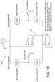
- FIGURE 17 depicts a transducer switching network 196 , comprised of 2 rows and 64 columns, although the network may employ more or less than 64 columns.
- the 2-row network 195 is implemented to improve the control of parasitic current paths.
- Network 195 functions under the same concepts as network 10 of FIGURES 1, 2 and 3. For example, a row 196 , and column 197 are selected which allows a current to flow through transducer 198 .
- unwanted current paths will exist. This will result in undesirable current flow through OFF transducers, such as unselected transducer 199 .
- Switching network 200 of FIGURE 18 is a simplified illustration of switching matrix 195 shown in FIGURE 17, further including a row compensation network 202 which conceptually operates in the same manner as row compensation network 162 of FIGURE 15. A difference between compensation network 162 and compensation network 202 , is found in that compensation network is required to only provide compensation for 2 rows. It is to be further understood that 2-row transducer switching matrix 195 may also be designed with a column compensation, such as column compensation network 72 of FIGURE 10, as well as with both row and column compensation networks.
- Using a 2-row transducer switching matrix achieves a reduction in the number of column driver chips and wire bonds compared to a system with a single row network, while also encountering less parasitic current paths than for transducer switching networks with 3 or more rows.
- the 2-row transducer switching matrix which implements row and column current path compensation, is able to achieve highly reliable switching ratio control. It is to be appreciated that while capacitors have been described in the compensation networks, other devices such as diodes, transistors, etc. may be used to control compensation current paths and magnitudes. Further, the present embodiments have focused on 4 and 2-row column matrixes, however other size matrixes may also implement the present invention.
Landscapes
- Particle Formation And Scattering Control In Inkjet Printers (AREA)
Applications Claiming Priority (2)
| Application Number | Priority Date | Filing Date | Title |
|---|---|---|---|
| US449038 | 1995-05-24 | ||
| US09/449,038 US6447086B1 (en) | 1999-11-24 | 1999-11-24 | Method and apparatus for achieving controlled RF switching ratios to maintain thermal uniformity in the acoustic focal spot of an acoustic ink printhead |
Publications (2)
| Publication Number | Publication Date |
|---|---|
| EP1103379A1 true EP1103379A1 (de) | 2001-05-30 |
| EP1103379B1 EP1103379B1 (de) | 2002-10-16 |
Family
ID=23782629
Family Applications (1)
| Application Number | Title | Priority Date | Filing Date |
|---|---|---|---|
| EP00125040A Expired - Lifetime EP1103379B1 (de) | 1999-11-24 | 2000-11-16 | Verfahren und Vorrichtung von gesteuerten RF-Schaltverhältnissen, um thermische Gleichmässigkeit im akustischen Brennpunkt eienes akustischen Tintendruckkopfes zu erreichen |
Country Status (4)
| Country | Link |
|---|---|
| US (1) | US6447086B1 (de) |
| EP (1) | EP1103379B1 (de) |
| JP (1) | JP4633916B2 (de) |
| DE (1) | DE60000601T2 (de) |
Families Citing this family (1)
| Publication number | Priority date | Publication date | Assignee | Title |
|---|---|---|---|---|
| US6746104B2 (en) * | 2000-09-25 | 2004-06-08 | Picoliter Inc. | Method for generating molecular arrays on porous surfaces |
Citations (3)
| Publication number | Priority date | Publication date | Assignee | Title |
|---|---|---|---|---|
| US5389956A (en) * | 1992-08-18 | 1995-02-14 | Xerox Corporation | Techniques for improving droplet uniformity in acoustic ink printing |
| EP0704304A1 (de) * | 1994-09-30 | 1996-04-03 | Xerox Corporation | Integrierte Varactor- und piezoelektrische Vorrichtung für akustisches Farbdrucken |
| EP0953451A2 (de) * | 1998-04-28 | 1999-11-03 | Xerox Corporation | Drucksystem mit phaseverschobenen Drucken zur Verminderung des Spitzenleistungverbrauchs |
Family Cites Families (17)
| Publication number | Priority date | Publication date | Assignee | Title |
|---|---|---|---|---|
| US3838412A (en) * | 1965-04-19 | 1974-09-24 | Gen Electric | Optical link for illuminated traveling message display sign system |
| US3727185A (en) * | 1965-04-19 | 1973-04-10 | Gen Electric | Time-share transmitter |
| DE2643918C3 (de) * | 1976-09-29 | 1986-10-23 | Siemens AG, 1000 Berlin und 8000 München | Gerät zur Ultraschallabtastung |
| US4751530A (en) | 1986-12-19 | 1988-06-14 | Xerox Corporation | Acoustic lens arrays for ink printing |
| US4745419A (en) | 1987-06-02 | 1988-05-17 | Xerox Corporation | Hot melt ink acoustic printing |
| US4801953A (en) | 1987-06-02 | 1989-01-31 | Xerox Corporation | Perforated ink transports for acoustic ink printing |
| US4782350A (en) | 1987-10-28 | 1988-11-01 | Xerox Corporation | Amorphous silicon varactors as rf amplitude modulators and their application to acoustic ink printers |
| US5126451A (en) | 1988-02-11 | 1992-06-30 | Warner-Lambert Company | Renin inhibitors containing α-heteroatom amino acids |
| US5122818A (en) | 1988-12-21 | 1992-06-16 | Xerox Corporation | Acoustic ink printers having reduced focusing sensitivity |
| US4959674A (en) | 1989-10-03 | 1990-09-25 | Xerox Corporation | Acoustic ink printhead having reflection coating for improved ink drop ejection control |
| US5144336A (en) * | 1990-01-23 | 1992-09-01 | Hewlett-Packard Company | Method and apparatus for controlling the temperature of thermal ink jet and thermal printheads that have a heating matrix system |
| US5087931A (en) | 1990-05-15 | 1992-02-11 | Xerox Corporation | Pressure-equalized ink transport system for acoustic ink printers |
| US5142307A (en) | 1990-12-26 | 1992-08-25 | Xerox Corporation | Variable orifice capillary wave printer |
| US5121141A (en) | 1991-01-14 | 1992-06-09 | Xerox Corporation | Acoustic ink printhead with integrated liquid level control layer |
| US5450107A (en) | 1991-12-27 | 1995-09-12 | Xerox Corporation | Surface ripple wave suppression by anti-reflection in apertured free ink surface level controllers for acoustic ink printers |
| US5339101A (en) | 1991-12-30 | 1994-08-16 | Xerox Corporation | Acoustic ink printhead |
| US5808636A (en) | 1996-09-13 | 1998-09-15 | Xerox Corporation | Reduction of droplet misdirectionality in acoustic ink printing |
-
1999
- 1999-11-24 US US09/449,038 patent/US6447086B1/en not_active Expired - Lifetime
-
2000
- 2000-11-16 DE DE60000601T patent/DE60000601T2/de not_active Expired - Lifetime
- 2000-11-16 EP EP00125040A patent/EP1103379B1/de not_active Expired - Lifetime
- 2000-11-20 JP JP2000352317A patent/JP4633916B2/ja not_active Expired - Fee Related
Patent Citations (3)
| Publication number | Priority date | Publication date | Assignee | Title |
|---|---|---|---|---|
| US5389956A (en) * | 1992-08-18 | 1995-02-14 | Xerox Corporation | Techniques for improving droplet uniformity in acoustic ink printing |
| EP0704304A1 (de) * | 1994-09-30 | 1996-04-03 | Xerox Corporation | Integrierte Varactor- und piezoelektrische Vorrichtung für akustisches Farbdrucken |
| EP0953451A2 (de) * | 1998-04-28 | 1999-11-03 | Xerox Corporation | Drucksystem mit phaseverschobenen Drucken zur Verminderung des Spitzenleistungverbrauchs |
Also Published As
| Publication number | Publication date |
|---|---|
| DE60000601D1 (de) | 2002-11-21 |
| EP1103379B1 (de) | 2002-10-16 |
| JP2001150662A (ja) | 2001-06-05 |
| JP4633916B2 (ja) | 2011-02-16 |
| DE60000601T2 (de) | 2003-02-27 |
| US6447086B1 (en) | 2002-09-10 |
Similar Documents
| Publication | Publication Date | Title |
|---|---|---|
| US5057855A (en) | Thermal ink jet printhead and control arrangement therefor | |
| US5644342A (en) | Addressing system for an integrated printhead | |
| US5006867A (en) | Recording head for an ink jet recording apparatus having a plurality of temperature detection elements | |
| JP2001063056A (ja) | インクジェット噴出システムおよび印字ヘッドの集積回路噴出セル | |
| US5600349A (en) | Method of reducing drive energy in a high speed thermal ink jet printer | |
| DE60300053T2 (de) | Ausstosspulsen in einem Flüssigkeitsausstossgerät | |
| US5363134A (en) | Integrated circuit printhead for an ink jet printer including an integrated identification circuit | |
| DE69926830T2 (de) | Energiesteuerungsverfahren für eine Tintenstrahldruckpatrone | |
| US6932453B2 (en) | Inkjet printhead assembly having very high drop rate generation | |
| JP3504367B2 (ja) | インク・ジェット・プリンタのための電圧降下用修正装置 | |
| US6431677B1 (en) | Print head drive scheme | |
| JP2863241B2 (ja) | 記録ヘッドおよび記録ヘッド駆動方法 | |
| US5389956A (en) | Techniques for improving droplet uniformity in acoustic ink printing | |
| US6286924B1 (en) | Apparatus and method for heating ink jet printhead | |
| US5519417A (en) | Power control system for a printer | |
| US5420618A (en) | Ink jet recording method and apparatus having drop size control by using plural control electrodes | |
| JPH08197732A (ja) | 記録ヘッド及び該記録ヘッドを用いた記録装置 | |
| EP1103379B1 (de) | Verfahren und Vorrichtung von gesteuerten RF-Schaltverhältnissen, um thermische Gleichmässigkeit im akustischen Brennpunkt eienes akustischen Tintendruckkopfes zu erreichen | |
| JP7830121B2 (ja) | 液体吐出ヘッド | |
| JP2000094692A (ja) | 記録ヘッド及びその記録ヘッドを用いた記録装置 | |
| JPS6345308B2 (de) | ||
| US7111920B2 (en) | Fluid jet head with driving circuit of a heater set | |
| US6761432B2 (en) | Ink jet recording head and ink jet recording apparatus | |
| JP3127663B2 (ja) | インクジェット記録装置および記録方法 | |
| DE60114324T2 (de) | Tintenstrahlaufzeichnungskopf und Tintenstrahlaufzeichnungsgerät |
Legal Events
| Date | Code | Title | Description |
|---|---|---|---|
| PUAI | Public reference made under article 153(3) epc to a published international application that has entered the european phase |
Free format text: ORIGINAL CODE: 0009012 |
|
| AK | Designated contracting states |
Kind code of ref document: A1 Designated state(s): DE FR GB |
|
| AX | Request for extension of the european patent |
Free format text: AL;LT;LV;MK;RO;SI |
|
| 17P | Request for examination filed |
Effective date: 20011130 |
|
| AKX | Designation fees paid |
Free format text: DE FR GB |
|
| GRAG | Despatch of communication of intention to grant |
Free format text: ORIGINAL CODE: EPIDOS AGRA |
|
| 17Q | First examination report despatched |
Effective date: 20020306 |
|
| GRAG | Despatch of communication of intention to grant |
Free format text: ORIGINAL CODE: EPIDOS AGRA |
|
| GRAH | Despatch of communication of intention to grant a patent |
Free format text: ORIGINAL CODE: EPIDOS IGRA |
|
| GRAH | Despatch of communication of intention to grant a patent |
Free format text: ORIGINAL CODE: EPIDOS IGRA |
|
| GRAA | (expected) grant |
Free format text: ORIGINAL CODE: 0009210 |
|
| AK | Designated contracting states |
Kind code of ref document: B1 Designated state(s): DE FR GB |
|
| REG | Reference to a national code |
Ref country code: GB Ref legal event code: FG4D |
|
| REF | Corresponds to: |
Ref document number: 60000601 Country of ref document: DE Date of ref document: 20021121 |
|
| ET | Fr: translation filed | ||
| PLBE | No opposition filed within time limit |
Free format text: ORIGINAL CODE: 0009261 |
|
| STAA | Information on the status of an ep patent application or granted ep patent |
Free format text: STATUS: NO OPPOSITION FILED WITHIN TIME LIMIT |
|
| 26N | No opposition filed |
Effective date: 20030717 |
|
| REG | Reference to a national code |
Ref country code: FR Ref legal event code: PLFP Year of fee payment: 16 |
|
| REG | Reference to a national code |
Ref country code: FR Ref legal event code: PLFP Year of fee payment: 17 |
|
| REG | Reference to a national code |
Ref country code: FR Ref legal event code: PLFP Year of fee payment: 18 |
|
| PGFP | Annual fee paid to national office [announced via postgrant information from national office to epo] |
Ref country code: DE Payment date: 20171019 Year of fee payment: 18 Ref country code: FR Payment date: 20171020 Year of fee payment: 18 |
|
| PGFP | Annual fee paid to national office [announced via postgrant information from national office to epo] |
Ref country code: GB Payment date: 20171020 Year of fee payment: 18 |
|
| REG | Reference to a national code |
Ref country code: DE Ref legal event code: R119 Ref document number: 60000601 Country of ref document: DE |
|
| GBPC | Gb: european patent ceased through non-payment of renewal fee |
Effective date: 20181116 |
|
| PG25 | Lapsed in a contracting state [announced via postgrant information from national office to epo] |
Ref country code: DE Free format text: LAPSE BECAUSE OF NON-PAYMENT OF DUE FEES Effective date: 20190601 Ref country code: FR Free format text: LAPSE BECAUSE OF NON-PAYMENT OF DUE FEES Effective date: 20181130 |
|
| PG25 | Lapsed in a contracting state [announced via postgrant information from national office to epo] |
Ref country code: GB Free format text: LAPSE BECAUSE OF NON-PAYMENT OF DUE FEES Effective date: 20181116 |