EP1103388A2 - Ordnermechanik - Google Patents
Ordnermechanik Download PDFInfo
- Publication number
- EP1103388A2 EP1103388A2 EP00125153A EP00125153A EP1103388A2 EP 1103388 A2 EP1103388 A2 EP 1103388A2 EP 00125153 A EP00125153 A EP 00125153A EP 00125153 A EP00125153 A EP 00125153A EP 1103388 A2 EP1103388 A2 EP 1103388A2
- Authority
- EP
- European Patent Office
- Prior art keywords
- punch
- mechanism according
- base plate
- folder
- plate
- Prior art date
- Legal status (The legal status is an assumption and is not a legal conclusion. Google has not performed a legal analysis and makes no representation as to the accuracy of the status listed.)
- Withdrawn
Links
Images


Classifications
-
- B—PERFORMING OPERATIONS; TRANSPORTING
- B42—BOOKBINDING; ALBUMS; FILES; SPECIAL PRINTED MATTER
- B42F—SHEETS TEMPORARILY ATTACHED TOGETHER; FILING APPLIANCES; FILE CARDS; INDEXING
- B42F13/00—Filing appliances with means for engaging perforations or slots
- B42F13/16—Filing appliances with means for engaging perforations or slots with claws or rings
- B42F13/20—Filing appliances with means for engaging perforations or slots with claws or rings pivotable about an axis or axes parallel to binding edges
- B42F13/22—Filing appliances with means for engaging perforations or slots with claws or rings pivotable about an axis or axes parallel to binding edges in two sections engaging each other when closed
- B42F13/24—Filing appliances with means for engaging perforations or slots with claws or rings pivotable about an axis or axes parallel to binding edges in two sections engaging each other when closed wherein one section is in the form of fixed rods
Definitions
- Sheets must be punched for filing in a folder. On Locher is - especially outside of professional office areas - not always at hand. Trying to get sheets with the help of the alignment pins Punching the folder yourself will usually damage the sheets.
- the invention is based on the object of specifying a folder mechanism, which is a clean filing of the respective sheets without separate Punch allows.
- the in the folder mechanics operate integrated punches with the same arrangement, for opening and closing the swivel bracket of the folder mechanism serves.
- the same spring or spring arrangement is also both for opening the swivel bracket and for pulling back the punch used. Both measures have the advantage that the integrated hole punch manages with a minimum of additional components.
- the serving plate according to claim 8 serves simultaneously as part of a collecting chamber for the punch die-cuts.
- the design of the invention according to claim 13 represents one less concentrated integration of folder mechanics and hole punches, so far is advantageous when the punch part with conventional folder mechanisms can be combined.
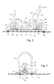
- the folder mechanism comprises a base plate 10 which has a base part 11 , a raised part 12 which is offset upwards in parallel with respect to this and a step part 13 which connects the parts 11 and 12 to one another and runs essentially perpendicular to them.
- the base part 11 of the base plate 10 is connected to the lower folder cover 15 by means of rivets 14 .
- two alignment pins 16 are attached, the upper free ends of which are tapered and, in the closed state of the file mechanism illustrated in FIG. 3, engage in corresponding recesses on the free ends of swivel brackets 17 .
- an essentially right-angled opening lever 28 is mounted, which has a handle part 29 at its other end and carries a rotatable roller 30 in the area of the crank which engages with the transverse lever section 25 stands.
- An intermediate plate 31 is arranged between the base plate 10 and file cover 15 and, like the base plate 10, has a base part 32 , a raised part 33 and a substantially vertical step part 34 connecting the parts 32 and 33 to one another.
- the raised part 33 of the intermediate plate 31 runs slightly obliquely downwards in the front region and forms, together with the raised part 12 of the base plate 10, an insertion slot 35 of the punch part of the arrangement, the depth of the insertion slot 35 forming a stop for the sheets to be punched Step part 13 of the base plate 10 is limited.
- the base part 32 of the intermediate plate 31 is fastened together with the base part 11 of the base plate 10 to the folder cover 15 by means of the rivets 14 .
- the front region of the raised part 33 of the intermediate plate 31 is bent in a U-shape downwards and inwards and is connected to the folder cover 15 by means of rivets 36 .
- a chamber 37 is delimited by the raised part 33 and the step part 34 of the intermediate plate in connection with the folder cover 15 , which is closed on the end face by (not shown) bent parts of the intermediate plate 31 and serves to receive the punched die-cuts.
- a slot-shaped opening formed in the folder cover 15 serves to empty the chamber 37 and is closed by a snap-in plastic cover 38 .
- the punch actuating sections 24 of the wire element 18 engage at the upper ends of punch dies 39 which are guided in bores in the raised part 12 of the base plate 10 and a guide plate 40 arranged above them.
- Each punch 39 is surrounded by a compression coil spring 41 , which is arranged between the raised part 12 of the base plate 10 and a snap ring attached to the punch and biases the punch 39 upwards. Since the upper ends of the pressure rams rest on the underside of the ram actuation sections 24 , the transverse lever section 25 and the pivot brackets 17 are also biased into the open position shown in FIG. 1 via these.
- the folder mechanism is opened from the closed position shown in FIG. 3 by lifting the opening lever 28 into the position shown in FIG. As a result, the pressure exerted by the roller 30 on the transverse lever section 25 is released, so that the compression springs 41 can lift the stamp actuating sections 24 , thereby pivoting the wire element 18 as a whole around the bearing sections 19 and moving the swivel bracket 17 into the position shown in FIG. 1.
- the sheet or sheets to be filed can now be inserted into the insertion slot 35 of the punch part.
- 15 markings for standard sheet formats can be provided on the folder cover for centering.
- the punches 39 are moved downward against the force of the compression springs 41 , their lower punched edges penetrating the inserted leaves and openings in the raised part 33 of the intermediate plate 31 and conveying the parts punched out of the leaves into the chamber 37 .
- the perforated paper sheets can be removed from the hole part and threaded onto the alignment pins 16 .
- the upper ends of the alignment pins 16 are connected to the swivel brackets 17 , whereby the punching and filing process is ended.
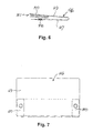
- FIGS. 4 and 5 differs from that according to FIGS. 1 to 3 essentially only in that, instead of the one-piece wire element 18, an actuating plate 42 is provided which is pivotably mounted in bearing elements 43 formed on the raised part 12 of the base plate 10 and the swivel bracket 17 carries.
- the area of the actuating plate 42 opposite the bearing elements 43 has a central area 44 , on which the roller 30 of the opening lever 28 engages.
- This surface area can be curved in order to stiffen and to ensure a good engagement with the roller 30 that is independent of the position of the actuating plate 42 .
- the lateral areas of the actuating plate 42 are cranked upward in a step-like manner and form stamp actuating sections 45 which abut the upper ends of the punch 39 .
- the punch 39 upwardly biasing springs 41 then cause when the opening lever is moved to the position shown in Figure 5 position 28 that the punch 39, the actuating plate pivot 42 to the position shown in Figure 4 inclined position, whereby the swivel bar is open in the 17 Position. If the opening lever 28 is moved downward, the swivel brackets 17 are closed as in the first exemplary embodiment described above and the punch 39 - optionally for punching sheets inserted into the insertion slot 35 - is moved downward.
- the punch part shown in FIGS. 6 and 7 consists of a U-shaped leaf spring 46 , the lower leg 47 of which carries two punch punches 48 and 49 receiving forks 50 are attached to the upper leg.
- the receiving forks of the leaf spring 46 mounted 50 on displaced parts of the upper leg 49 so that the punching edge having a generally planar upper surface on which a conventional file mechanism can (shown not) be established, while the lower leg 47 of the leaf spring 46 is used for attachment to the respective folder cover (not shown).
- the front area of the upper leg 49 and the lower leg of the respective receiving fork 50 form an insertion slot 51 . Introduced sheets are punched in that the folder mechanism attached to the upper leg 49 is pivoted while compressing the U-shaped leaf spring 46 , the punch 48 passing through corresponding holes in the receiving forks 50 . This punching process can be carried out regardless of the open state of the folder mechanism.
Landscapes
- Perforating, Stamping-Out Or Severing By Means Other Than Cutting (AREA)
- Mounting, Exchange, And Manufacturing Of Dies (AREA)
Abstract
Description
- Figur 1
- eine Seitenansicht einer Ordnermechanik mit integriertem Locher im geöffneten Zustand,
- Figur 2
- eine Rückansicht der Mechanik nach Figur 1,
- Figur 3
- eine Seitenansicht der Mechanik nach Figur 1 und 2 im geschlossenen Zustand,
- Figur 4
- eine der Figur 1 ähnliche Seitenansicht einer weiteren Ausführungsform der Ordnermechanik mit integriertem Locher in geöffneter Stellung,
- Figur 5
- eine der Figur 2 entsprechende Darstellung der Mechanik nach Figur 1,
- Figur 6
- eine Seitenansicht eines zur Integration mit einer Ordnermechanik geeigneten Locherteils gemäß einer dritten Ausführungsform, und
- Figur 7
- eine Draufsicht auf den Locherteil nach Figur 6.
- zwei miteinander fluchtende Lagerabschnitte 19, deren jeder von dem betreffenden Schwenkbügel 17 rechtwinklig nach außen gekröpft ist und eine Lagerbuchse 20 durchsetzt, die von einer aus dem erhabenen Teil 12 der Grundplatte 10 freigeschnittenen und herausgebogenen Blechzunge gebildet ist;
- zwei Übergangsabschnitte 21, deren jeder einen im geschlossenen Zustand (Figur 3) der Ordnermechanik parallel zu dem erhabenen Teil 12 der Grundplatte 10 verlaufenden ersten Abschnitt 22 und einen von diesem rechtwinklig nach oben gekröpften zweiten Abschnitt 23 (vergl. insbesondere Figur 1) umfaßt;
- zwei miteinander fluchtende Stempelbetätigungsabschnitte 24, deren jeder gegenüber dem zweiten Abschnitt 23 des betreffenden Übergangsabschnitts 21 rechtwinklig gekröpft ist und parallel zu der Grundplatte 10 verläuft; und
- einen Querhebelabschnitt 25, der parallel zur Grundplatte 10 verläuft, sich gegenüber den Stempelbetätigungsabschnitten 24 näher an dem erhabenen Teil 12 der Grundplatte 10 befindet und mit den Stempelbetätigungsabschnitten 24 jeweils über einen schräg verlaufenden Verbindungsabschnitt 26 verbunden ist.
- 10
- Grundplatte
- 11
- Basisteil
- 12
- erhabener Teil
- 13
- Stufenteil
- 14
- Nieten
- 15
- Ordnerdeckel
- 16
- Aufreihstifte
- 17
- Schwenkbügel
- 18
- Drahtelement
- 19
- Lagerabschnitte
- 20
- Lagerbuchse
- 21
- Übergangsabschnitte
- 22
- erster Abschnitt von 21
- 23
- zweiter Abschnitt von 21
- 24
- Stempelbetätigungsabschnitt
- 25
- Querhebelabschnitt
- 26
- Verbindungsabschnitt
- 27
- Stütze
- 28
- Öffnungshebel
- 29
- Griffteil
- 30
- Rolle
- 31
- Zwischenplatte
- 32
- Basisteil
- 33
- erhabener Teil
- 34
- Stufenteil
- 35
- Einführschlitz
- 36
- Nieten
- 37
- Kammer
- 38
- Deckel
- 39
- Lochstempel
- 40
- Führungsplatte
- 41
- Druckfeder
- 42
- Betätigungsplatte
- 43
- Lagerelemente
- 44
- mittlerer Bereich von 42
- 45
- Stempelbetätigungsabschnitt
- 46
- Blattfeder
- 47
- unterer Schenkel von 46
- 48
- Lochstempel
- 49
- oberer Schenkel von 46
- 50
- Aufnahmegabeln
- 51
- Einführschlitz
Claims (15)
- Ordnermechanik mit einer Grundplatte (10; 46) zur Befestigung am Ordner, dadurch gekennzeichnet, daß die Grundplatte (10; 46) Teil eines Lochers ist.
- Mechanik nach Anspruch 1, wobei die Lochstempel (39) des Lochers mit den Schwenkbügeln (17) der Ordnermechanik bewegungsgekoppelt sind.
- Mechanik nach Anspruch 2, wobei mindestens einer der Lochstempel (39) von einer Schraubenfeder (41) umgeben ist, die die Rückstellkraft für die Lochstempel (39) und die Öffnungskraft für die Schwenkbügel (17) liefert.
- Mechanik nach Anspruch 2 oder 3, wobei die Grundplatte (10) einen die Aufreihstifte (16) der Ordnermechanik tragenden Basisteil (11) und einen gegenüber diesem nach oben versetzten erhabenen Teil (12) aufweist, an dessen Oberseite die Schwenkbügel (17) gelagert sind.
- Mechanik nach Anspruch 4, wobei der erhabene Teil (12) der Grundplatte (10) mit dem Basisteil (11) über einen im wesentlichen senkrechten Stufenteil (13) verbunden ist, der eine Anschlagfläche für zu lochende Blätter bildet.
- Mechanik nach Anspruch 5, wobei der Stufenteil (13) von den Aufreihstiften (16) einen größeren Abstand hat als von den Lochstempeln (39).
- Mechanik nach einem der Ansprüche 4 bis 6, wobei auf der dem Ordner zugewandten Seite der Grundplatte (10) eine Zwischenplatte (31) mit einem Basisteil (32) und einem diesem gegenüber nach oben versetzten erhabenen Teil (33) angeordnet ist, der mit dem erhabenen Teil (12) der Grundplatte (10) einen Einführschlitz (35) für zu lochende Blätter bildet.
- Mechanik nach Anspruch 7, wobei die Zwischenplatte (31) Wände einer Auffangkammer (37) für Locher-Stanzlinge bildet.
- Mechanik nach einem der Ansprüche 2 bis 8, wobei die Schwenkbügel (17) über ein Bauteil (18; 42) miteinander verbunden sind, das einen mittleren Bereich (25; 44) zum Eingriff mit einem Öffnungshebel (28) und seitliche Bereich (24; 45) zur Betätigung der Lochstempel (39) aufweist.
- Mechanik nach Anspruch 9, wobei das Bauteil (18) an den äußeren Enden der die Lochstempel (39) betätigenden seitlichen Bereiche (24) jeweils zurückgebogen ist, so daß zwei koaxial aufeinander zu verlaufende Lagerbereiche (19) entstehen, die an ihren einander zugewandten Enden unter Bildung jeweils eines der Schwenkbügel (17) gekröpft sind.
- Mechanik nach Anspruch 9, wobei das Bauteil eine Betätigungsplatte (42) umfaßt, an der die Schwenkbügel (17) fixiert sind.
- Mechanik nach Anspruch 11, wobei die die Lochstempel (39) betätigenden seitlichen Bereiche (45) der Betätigungsplatte (42) gegenüber dem mit dem Öffnungshebel (28) in Eingriff stehenden mittleren Bereich (44) von der Grundplatte (10) weg versetzt sind.
- Mechanik nach Anspruch 1, wobei die Grundplatte von einer U-förmig gebogenen Blattfeder (46) gebildet ist, deren einer Schenkel (47) mit Lochstempeln (48) und deren anderer Schenkel (49) mit einer Aufnahmegabel (50) für zu lochende Blätter versehen ist.
- Mechanik nach Anspruch 13, wobei die Blattfeder (46) mit ihrem unteren Schenkel (47) am Ordner fixierbar ist und an ihrem oberen Schenkel (49) die übrigen Bestandteile der Ordnermechanik trägt.
- Mechanik nach Anspruch 13 oder 14, wobei die Lochstempel (48) am unteren Schenkel (47) der Blattfeder (46) vorgesehen sind.
Applications Claiming Priority (2)
| Application Number | Priority Date | Filing Date | Title |
|---|---|---|---|
| DE19955813 | 1999-11-19 | ||
| DE1999155813 DE19955813C2 (de) | 1999-11-19 | 1999-11-19 | Ordnermechanik mit integriertem Locher |
Publications (2)
| Publication Number | Publication Date |
|---|---|
| EP1103388A2 true EP1103388A2 (de) | 2001-05-30 |
| EP1103388A3 EP1103388A3 (de) | 2002-01-16 |
Family
ID=7929690
Family Applications (1)
| Application Number | Title | Priority Date | Filing Date |
|---|---|---|---|
| EP00125153A Withdrawn EP1103388A3 (de) | 1999-11-19 | 2000-11-17 | Ordnermechanik |
Country Status (2)
| Country | Link |
|---|---|
| EP (1) | EP1103388A3 (de) |
| DE (1) | DE19955813C2 (de) |
Cited By (2)
| Publication number | Priority date | Publication date | Assignee | Title |
|---|---|---|---|---|
| WO2004052658A1 (en) * | 2002-12-08 | 2004-06-24 | Lap-Institute For Advanced Surgery Ltd. | A combined document binder and paper punch |
| WO2008155577A1 (en) * | 2007-06-21 | 2008-12-24 | Jabar Hussain | Punch file |
Families Citing this family (1)
| Publication number | Priority date | Publication date | Assignee | Title |
|---|---|---|---|---|
| DE102011001419A1 (de) * | 2011-03-18 | 2012-09-20 | Klaus Hager | Heftmechanismus mit einem Stanzelement |
Family Cites Families (7)
| Publication number | Priority date | Publication date | Assignee | Title |
|---|---|---|---|---|
| DE368462C (de) * | 1923-02-06 | Giuseppe Tonelli | Briefordnermechanik mit einer beim Schliessen der Aufreihbuegel in Taetigkeit tretenden Lochvorrichtung | |
| DE2241185A1 (de) * | 1972-08-22 | 1974-03-07 | Ulrich Lammers | Ordner mit locher |
| DE2751359A1 (de) * | 1977-11-17 | 1979-05-23 | Georg Fendt | Ordner mit locher |
| DE2810955A1 (de) * | 1978-03-14 | 1979-09-27 | Georg Fendt | Ordner mit locher |
| DE2947367A1 (de) * | 1979-11-24 | 1981-05-27 | Bessey & Sohn Gmbh & Co, 7000 Stuttgart | Ablagevorrichtung zum ablegen losen gelochten schriftgutes |
| NO893875L (no) * | 1989-09-29 | 1991-04-02 | Inge Wengstad | Anordning ved ringperm. |
| DE29811943U1 (de) * | 1998-06-30 | 1998-09-03 | Manjah, Tony, Dipl.-Ing., 17033 Neubrandenburg | Aktenordner |
-
1999
- 1999-11-19 DE DE1999155813 patent/DE19955813C2/de not_active Expired - Fee Related
-
2000
- 2000-11-17 EP EP00125153A patent/EP1103388A3/de not_active Withdrawn
Cited By (2)
| Publication number | Priority date | Publication date | Assignee | Title |
|---|---|---|---|---|
| WO2004052658A1 (en) * | 2002-12-08 | 2004-06-24 | Lap-Institute For Advanced Surgery Ltd. | A combined document binder and paper punch |
| WO2008155577A1 (en) * | 2007-06-21 | 2008-12-24 | Jabar Hussain | Punch file |
Also Published As
| Publication number | Publication date |
|---|---|
| DE19955813C2 (de) | 2002-02-07 |
| EP1103388A3 (de) | 2002-01-16 |
| DE19955813A1 (de) | 2001-06-07 |
Similar Documents
| Publication | Publication Date | Title |
|---|---|---|
| DE102004021411B4 (de) | Papierschneidevorrichtung und Halteeinrichtung hierfür | |
| DE19526385B4 (de) | Vorrichtung zum Klemmen von Papierblättern während des Perforierens und zum Binden derselben in einem Ringbinder | |
| DE2422023A1 (de) | Brieflocher | |
| EP0446702B1 (de) | Vorrichtung zum Entfernen von ausbrechteilen aus einem Werkstoffbogen od.dgl. | |
| DE4429775A1 (de) | Ringbinder mit Papierlochungsmechanismus | |
| DE20118242U1 (de) | Papierlocher mit mehreren Stanzgliedern | |
| DE3117088C2 (de) | Vorrichtung zum Erzeugen eines kuppelgliederfreien Bereichs in zwei Reißverschlußbändern | |
| EP0067973B1 (de) | Locher für Blatt- und Folienförmiges Material | |
| DE102004039040B4 (de) | Lochstanze | |
| EP0314664B1 (de) | Bodenplatte für Aktenordner | |
| DE20118241U1 (de) | Papierlocher | |
| EP1103388A2 (de) | Ordnermechanik | |
| DE3814000C2 (de) | ||
| DE19518500A1 (de) | Bindevorrichtung zum Binden von Papierstapeln | |
| DE3534805A1 (de) | Locher, insbesondere buerolocher | |
| DE2947367A1 (de) | Ablagevorrichtung zum ablegen losen gelochten schriftgutes | |
| DE1018841B (de) | Lochstanze, insbesondere zum Lochen von Papierlagen | |
| DE3016168C2 (de) | Gesamtverbundschneid- und Biegewerkzeug | |
| DE3225776C2 (de) | Locher | |
| DE3029057A1 (de) | Locher fuer papier- und pappwaren | |
| DE4447256C2 (de) | Locher zur Ausbildung einer Mehrzahl von Löchern | |
| DE3339742A1 (de) | Vorrichtung zum lochen von duennen folien, insbesondere papier | |
| DE4312993C2 (de) | Kartenleser | |
| AT404699B (de) | Verschlussmechanik | |
| DE3326479C2 (de) | Brieflocher |
Legal Events
| Date | Code | Title | Description |
|---|---|---|---|
| PUAI | Public reference made under article 153(3) epc to a published international application that has entered the european phase |
Free format text: ORIGINAL CODE: 0009012 |
|
| AK | Designated contracting states |
Kind code of ref document: A2 Designated state(s): AT BE CH CY DE DK ES FI FR GB GR IE IT LI LU MC NL PT SE TR |
|
| AX | Request for extension of the european patent |
Free format text: AL;LT;LV;MK;RO;SI |
|
| PUAL | Search report despatched |
Free format text: ORIGINAL CODE: 0009013 |
|
| AK | Designated contracting states |
Kind code of ref document: A3 Designated state(s): AT BE CH CY DE DK ES FI FR GB GR IE IT LI LU MC NL PT SE TR |
|
| AX | Request for extension of the european patent |
Free format text: AL;LT;LV;MK;RO;SI |
|
| RIC1 | Information provided on ipc code assigned before grant |
Free format text: 7B 42F 13/24 A, 7B 42F 13/40 B |
|
| AKX | Designation fees paid | ||
| REG | Reference to a national code |
Ref country code: DE Ref legal event code: 8566 |
|
| STAA | Information on the status of an ep patent application or granted ep patent |
Free format text: STATUS: THE APPLICATION IS DEEMED TO BE WITHDRAWN |
|
| 18D | Application deemed to be withdrawn |
Effective date: 20020717 |