EP1103396B1 - Système de réglage de roulis de véhicule - Google Patents
Système de réglage de roulis de véhicule Download PDFInfo
- Publication number
- EP1103396B1 EP1103396B1 EP00203972A EP00203972A EP1103396B1 EP 1103396 B1 EP1103396 B1 EP 1103396B1 EP 00203972 A EP00203972 A EP 00203972A EP 00203972 A EP00203972 A EP 00203972A EP 1103396 B1 EP1103396 B1 EP 1103396B1
- Authority
- EP
- European Patent Office
- Prior art keywords
- fluid
- housing
- hydraulic actuator
- control system
- arm
- Prior art date
- Legal status (The legal status is an assumption and is not a legal conclusion. Google has not performed a legal analysis and makes no representation as to the accuracy of the status listed.)
- Expired - Lifetime
Links
- 239000012530 fluid Substances 0.000 claims description 122
- 238000007789 sealing Methods 0.000 claims description 6
- 230000001419 dependent effect Effects 0.000 claims description 3
- 238000007373 indentation Methods 0.000 claims description 3
- 238000001514 detection method Methods 0.000 claims 2
- 230000035939 shock Effects 0.000 description 5
- 239000006096 absorbing agent Substances 0.000 description 4
- 238000010586 diagram Methods 0.000 description 4
- 230000006835 compression Effects 0.000 description 3
- 238000007906 compression Methods 0.000 description 3
- 230000001133 acceleration Effects 0.000 description 2
- 230000004048 modification Effects 0.000 description 2
- 238000012986 modification Methods 0.000 description 2
- 230000000694 effects Effects 0.000 description 1
Images





Classifications
-
- B—PERFORMING OPERATIONS; TRANSPORTING
- B60—VEHICLES IN GENERAL
- B60G—VEHICLE SUSPENSION ARRANGEMENTS
- B60G17/00—Resilient suspensions having means for adjusting the spring or vibration-damper characteristics, for regulating the distance between a supporting surface and a sprung part of vehicle or for locking suspension during use to meet varying vehicular or surface conditions, e.g. due to speed or load
- B60G17/015—Resilient suspensions having means for adjusting the spring or vibration-damper characteristics, for regulating the distance between a supporting surface and a sprung part of vehicle or for locking suspension during use to meet varying vehicular or surface conditions, e.g. due to speed or load the regulating means comprising electric or electronic elements
- B60G17/0152—Resilient suspensions having means for adjusting the spring or vibration-damper characteristics, for regulating the distance between a supporting surface and a sprung part of vehicle or for locking suspension during use to meet varying vehicular or surface conditions, e.g. due to speed or load the regulating means comprising electric or electronic elements characterised by the action on a particular type of suspension unit
-
- B—PERFORMING OPERATIONS; TRANSPORTING
- B60—VEHICLES IN GENERAL
- B60G—VEHICLE SUSPENSION ARRANGEMENTS
- B60G17/00—Resilient suspensions having means for adjusting the spring or vibration-damper characteristics, for regulating the distance between a supporting surface and a sprung part of vehicle or for locking suspension during use to meet varying vehicular or surface conditions, e.g. due to speed or load
- B60G17/015—Resilient suspensions having means for adjusting the spring or vibration-damper characteristics, for regulating the distance between a supporting surface and a sprung part of vehicle or for locking suspension during use to meet varying vehicular or surface conditions, e.g. due to speed or load the regulating means comprising electric or electronic elements
- B60G17/016—Resilient suspensions having means for adjusting the spring or vibration-damper characteristics, for regulating the distance between a supporting surface and a sprung part of vehicle or for locking suspension during use to meet varying vehicular or surface conditions, e.g. due to speed or load the regulating means comprising electric or electronic elements characterised by their responsiveness, when the vehicle is travelling, to specific motion, a specific condition, or driver input
- B60G17/0162—Resilient suspensions having means for adjusting the spring or vibration-damper characteristics, for regulating the distance between a supporting surface and a sprung part of vehicle or for locking suspension during use to meet varying vehicular or surface conditions, e.g. due to speed or load the regulating means comprising electric or electronic elements characterised by their responsiveness, when the vehicle is travelling, to specific motion, a specific condition, or driver input mainly during a motion involving steering operation, e.g. cornering, overtaking
-
- B—PERFORMING OPERATIONS; TRANSPORTING
- B60—VEHICLES IN GENERAL
- B60G—VEHICLE SUSPENSION ARRANGEMENTS
- B60G21/00—Interconnection systems for two or more resiliently-suspended wheels, e.g. for stabilising a vehicle body with respect to acceleration, deceleration or centrifugal forces
- B60G21/02—Interconnection systems for two or more resiliently-suspended wheels, e.g. for stabilising a vehicle body with respect to acceleration, deceleration or centrifugal forces permanently interconnected
- B60G21/04—Interconnection systems for two or more resiliently-suspended wheels, e.g. for stabilising a vehicle body with respect to acceleration, deceleration or centrifugal forces permanently interconnected mechanically
- B60G21/05—Interconnection systems for two or more resiliently-suspended wheels, e.g. for stabilising a vehicle body with respect to acceleration, deceleration or centrifugal forces permanently interconnected mechanically between wheels on the same axle but on different sides of the vehicle, i.e. the left and right wheel suspensions being interconnected
- B60G21/055—Stabiliser bars
- B60G21/0551—Mounting means therefor
- B60G21/0553—Mounting means therefor adjustable
- B60G21/0555—Mounting means therefor adjustable including an actuator inducing vehicle roll
-
- B—PERFORMING OPERATIONS; TRANSPORTING
- B60—VEHICLES IN GENERAL
- B60G—VEHICLE SUSPENSION ARRANGEMENTS
- B60G2202/00—Indexing codes relating to the type of spring, damper or actuator
- B60G2202/10—Type of spring
- B60G2202/13—Torsion spring
- B60G2202/135—Stabiliser bar and/or tube
-
- B—PERFORMING OPERATIONS; TRANSPORTING
- B60—VEHICLES IN GENERAL
- B60G—VEHICLE SUSPENSION ARRANGEMENTS
- B60G2202/00—Indexing codes relating to the type of spring, damper or actuator
- B60G2202/40—Type of actuator
- B60G2202/41—Fluid actuator
- B60G2202/413—Hydraulic actuator
-
- B—PERFORMING OPERATIONS; TRANSPORTING
- B60—VEHICLES IN GENERAL
- B60G—VEHICLE SUSPENSION ARRANGEMENTS
- B60G2202/00—Indexing codes relating to the type of spring, damper or actuator
- B60G2202/40—Type of actuator
- B60G2202/41—Fluid actuator
- B60G2202/414—Fluid actuator using electrohydraulic valves
-
- B—PERFORMING OPERATIONS; TRANSPORTING
- B60—VEHICLES IN GENERAL
- B60G—VEHICLE SUSPENSION ARRANGEMENTS
- B60G2400/00—Indexing codes relating to detected, measured or calculated conditions or factors
- B60G2400/10—Acceleration; Deceleration
- B60G2400/104—Acceleration; Deceleration lateral or transversal with regard to vehicle
-
- B—PERFORMING OPERATIONS; TRANSPORTING
- B60—VEHICLES IN GENERAL
- B60G—VEHICLE SUSPENSION ARRANGEMENTS
- B60G2400/00—Indexing codes relating to detected, measured or calculated conditions or factors
- B60G2400/20—Speed
- B60G2400/204—Vehicle speed
-
- B—PERFORMING OPERATIONS; TRANSPORTING
- B60—VEHICLES IN GENERAL
- B60G—VEHICLE SUSPENSION ARRANGEMENTS
- B60G2400/00—Indexing codes relating to detected, measured or calculated conditions or factors
- B60G2400/40—Steering conditions
- B60G2400/41—Steering angle
-
- B—PERFORMING OPERATIONS; TRANSPORTING
- B60—VEHICLES IN GENERAL
- B60G—VEHICLE SUSPENSION ARRANGEMENTS
- B60G2400/00—Indexing codes relating to detected, measured or calculated conditions or factors
- B60G2400/50—Pressure
-
- B—PERFORMING OPERATIONS; TRANSPORTING
- B60—VEHICLES IN GENERAL
- B60G—VEHICLE SUSPENSION ARRANGEMENTS
- B60G2800/00—Indexing codes relating to the type of movement or to the condition of the vehicle and to the end result to be achieved by the control action
- B60G2800/01—Attitude or posture control
- B60G2800/012—Rolling condition
Definitions
- the present invention relates to a roll control system for a motor vehicle.
- GB-A-2230237 discloses a roll control system comprising a torsion bar, a first arm fixedly connected to one end of the torsion bar, and a second arm rotatably connected to the other end of the torsion bar by way of a rotary actuator.
- the rotary actuator is operable to effect relative angular movement between the second arm and the said other end of the torsion bar. This arrangement is such that the actuator has to generate a large amount of force in order to provide the required roll control.
- GB-A-2284184 describes a roll control system in which a hydraulic cylinder is used to prevent or allow rotation of an arm attached to a torsion bar between the torsion bar and an axle of a wheel. This arrangement provides a limited amount of roll control.
- EP-A-0783986 describes an arrangement which is similar in layout to GB-A-2284184 but in which the hydraulic actuators are powered to provided active roll control for the vehicle.
- EP-A-0512358 describes a twin-axle roll control system which makes use of an attitude sensor for controlling roll.
- the aim of the present invention is to provide a roll control system which is an improvement to the above mentioned arrangements.
- a vehicle roll control system in accordance with the present invention for a vehicle having a pair of wheels each rotatable on an axle is characterised by the features specified in Claim 1.
- the present invention provides active roll control with reduced hydraulic fluid flow and/or improved ride comfort.
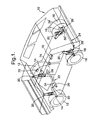
- a vehicle 10 is shown schematically and comprises a pair of front wheels 12 each rotatably mounted on an axle 14, a pair of rear wheels 16 each rotatably mounted on an axle 18, and a shock absorbing system 20 associated with each wheel.
- a portion 22 of a vehicle roll control system in accordance with the present invention is associated with the front wheels 12, and a portion 24 of the vehicle roll control system in accordance with the present invention is associated with the rear wheels 16.
- the portions 22, 24 are substantially the same but with modifications made solely to allow fitting to the vehicle 10.
- the portion 22 of the vehicle roll control system for the front of the vehicle comprises a torsion bar 26, a first arm 28, a second arm 30, a lever arm 32, and a hydraulic actuator 34.
- the torsion bar 26 is mounted on the vehicle by a pair of resilient mounts 36 in conventional manner to extend longitudinally between the wheels 12.
- the first arm 28 ( Figure 3 ) is fixed at one end 38 by a splined connection 40 to the torsion bar 26.
- the other end 42 of the first arm 28 is connected to the axle 14 of one of the front wheels 12 by a tie rod 43.
- the second arm 30 ( Figure 4 ) is rotatably mounted at one end 44 on the torsion bar 26 by way of a bearing 46.
- the other end 48 of the second arm 30 is connected to the axle 14 of the other front wheel 12 by a tie rod 49.
- the first and second arms 28,30 extend substantially parallel to one another when the vehicle is stationary, and substantially perpendicular to the torsion bar 26.
- the lever arm 32 ( Figure 4 ) is fixed at one end 50 to the torsion bar 26 by a splined connection 52 substantially adjacent the one end 44 of the second arm 30 and the bearing 46.
- the lever arm 32 extends substantially perpendicular to the torsion bar 26 to a free end 54.
- the hydraulic actuator 34 ( Figure 4 ) extends between, and is connected to, the free end 54 of the lever arm 32 and the other end 48 of the second arm 30.
- the hydraulic actuator 34 comprises a housing 56 which defines first and second fluid chambers 58,60 separated by a piston 62 which makes a sealing sliding fit with the housing.
- the housing 56 is connected to the other end 48 of the second arm 30, and the piston 62 is connected to the free end 54 of the lever arm 34 by a piston rod 64 which extends through the second fluid chamber 60. It will be appreciated that these connections may be reversed.
- the fluid chambers 58,60 contain hydraulic fluid and are fluidly connected to fluid lines 66, 68 respectively.
- the portion 24 of the vehicle roll control for the rear of the vehicle is substantially the same, but with the components (which are primed) having a different layout.
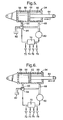
- the hydraulic and electrical control circuit of the vehicle roll control system is shown in Figures 5 and 6 .
- the hydraulic circuit includes a fluid pump 80, a fluid reservoir 82, and a directional valve 84.
- the fluid line 66, and hence the first fluid chamber 58, is connected to the directional valve 84.
- the fluid line 68, and hence the second fluid chamber 60, is connected to the fluid pump 80.
- the directional valve 84 is connected to the fluid pump 80 and to the reservoir 82.
- the directional valve 84 is operable between a first position ( Figure 5 ) in which the fluid pump 80 is connected to the first fluid chamber 58, and the reservoir 82 is isolated; and a second position ( Figure 6 ) in which the first fluid chamber is connected to the reservoir, and the fluid pump is isolated.
- the electrical control circuit includes an electronic and/or computerised control module 70.
- the control module 70 operates the fluid pump 80 and the directional valve 84 when required.
- the control module 70 operates the pump 80 and the valve 84 dependent on predetermined vehicle conditions which are determined by signals from one or more sensors, such as a pressure sensor 76 (which detects the presence of fluid pressure in the hydraulic circuit), a lateral g sensor 74 (which monitors the sideways acceleration of the vehicle), a steering sensor 72 (which monitors the steering angle of the front wheels 12), a vehicle speed sensor 78, and/or any other relevant parameter.
- sensors such as a pressure sensor 76 (which detects the presence of fluid pressure in the hydraulic circuit), a lateral g sensor 74 (which monitors the sideways acceleration of the vehicle), a steering sensor 72 (which monitors the steering angle of the front wheels 12), a vehicle speed sensor 78, and/or any other relevant parameter.
- control module 70 If the control module 70 detects that roll control is not required (that is, the vehicle is travelling in a straight line), the control module switches off the pump 80. Fluid can freely flow within the hydraulic system including between the two fluid chambers 58,60, of each hydraulic actuator 34, 34' allowing free movement of the piston 62 relative to the housing 56 thereby allowing free rotation of each second arm 30, 30' relative to its associated torsion bar 26, 26'.
- control module 70 determines if the motion will generate a force F which acts on the piston rod 64 to extend the actuator 34, or to compress the actuator, in an axial direction. If the former case, the control module 70 actuates the pump 80 and sets the directional valve 84 in the first position as shown in Figure 5 , so that the same fluid pressure is generated in each of the fluid chambers 58,60. If the latter case, the control module 70 actuates the pump 80 and sets the directional valve 84 in the second position as shown in Figure 6 , so that the fluid in the second fluid chamber 60 is pressurised, but the first fluid chamber 58 is connected to the reservoir 82.
- the actuator 34 By restricting connection of the first fluid chamber 58 to the reservoir 82 only during compression of the actuator 34, the amount of fluid flow within the hydraulic circuit is reduced during roll control.
- the output force from the actuator can be made substantially the same irrespective of the direction of motion of the piston 62.
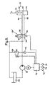
- the hydraulic circuit includes a fluid pump 80, a fluid reservoir 82, a single directional valve 184, and a pressure control valve 188.
- the directional valve 184 has a first port 90 fluidly connected to the output of the pump 80, a second port 92 fluidly connected to input to the reservoir 82, a third port 94 fluidly connected to the fluid line 66 and the first fluid chamber 58 of each hydraulic actuator 34,34', and a fourth port 96 fluidly connected to the fluid line 68 and the second fluid chamber 60 of each hydraulic actuator.
- the directional valve 184 is solenoid actuated and has a de-energised state (shown in Figure 7 ) in which the first and second ports 90,92 are fluidly connected and the third and fourth ports 94, 96 are isolated from all the other ports.
- the directional valve 184 has a first energised or actuated state in which the first port 90 is fluidly connected with the third and fourth ports 94,96, and in which the second port 92 is closed or isolated.
- the directional valve 184 has a second energised or actuated state in which the first port 90 is fluidly connected with the fourth port 96 and the second port 92 is fluidly connected with the third port 94.
- the pressure control valve 188 is fluidly connected between the output of the pump 80 and the input of the reservoir 82.
- the pump 80 is driven by the vehicle engine and hence continuously actuated, and the pressure control valve 188 is actuated to adjust the fluid pressure in the hydraulic system between a predetermined minimum pressure and a predetermined maximum pressure.
- the pump 80 may be driven by an electric motor or any other suitable means, either continuously, or variably (in which case the pressure control valve may be omitted).
- the electrical control circuit includes an electronic and/or computerised control module 70.
- the control module 70 operates the fluid pump 80, the directional valve 184, and the pressure control valve 188, when required.
- the control module 70 actuates the valves 184,188 dependent on predetermined vehicle conditions which are determined by signals from one or more sensors, such as a pressure sensor 76 (which detects the presence of fluid pressure in the hydraulic circuit), a lateral g sensor 74 (which monitors the sideways acceleration of the vehicle), a steering sensor 72 (which monitors the steering angle of the front wheels 12), a vehicle speed sensor 78, and/or any other relevant parameter.
- a pressure sensor 76 which detects the presence of fluid pressure in the hydraulic circuit
- a lateral g sensor 74 which monitors the sideways acceleration of the vehicle
- a steering sensor 72 which monitors the steering angle of the front wheels 12
- vehicle speed sensor 78 and/or any other relevant parameter.
- control module 70 If the control module 70 detects that roll control is not required (that is, the vehicle is travelling in a straight line), the control module actuates the pressure control valve 188 to provide the predetermined minimum pressure, and de-energises the directional valve 184. Fluid can freely flow within the hydraulic system between the pump 80 and the reservoir 82. As the directional valve 184 is closed, the actuators 34,34' are effectively locked.
- control module 70 determines if the motion will generate a force F which acts on the piston rod 64 to extend the actuators 34,34', or to compress the actuators, in an axial direction. If the former case, the control module 70 actuates the pressure control valve 188 to provide a fluid pressure in the hydraulic system which correlates with the force F, and sets the directional valve 184 in the first actuated position, so that the same fluid pressure is generated in each of the fluid chambers 58,60 of each actuator 34,34'.
- the control module 70 actuates the pressure control valve 188 to provide a fluid pressure in the hydraulic system which correlates with the force F, and sets the directional valve 184 in the second actuated position, so that the fluid in the second fluid chamber 60 of each actuator 34,34' is pressurised, but the first fluid chamber 58 of each actuator is connected to the reservoir 82.
- the amount of fluid flow within the hydraulic circuit is reduced during roll control.
- FIG. 8 A further alternative arrangement for the hydraulic and electrical control circuit is shown in Figure 8 .
- This further alternative embodiment is a modification of the arrangement shown in Figure 7 , for use with a single hydraulic actuator 34.
- the single directional valve 184' has a de-actuated state (as shown in Figure 8 ) in which the first port 90 is connected to the third and fourth ports 94,96, and the second port is isolated, and an actuated state in which the first port is fluidly connected to the fourth port, and the second port is fluidly connected to the third port.
- the directional valve 184' is de-actuated and the pressure control valve 188 is set to the predetermined minimum pressure, and fluid can freely flow between the fluid chambers 58,60.
- the direction valve 184' When roll control is required which requires the actuator 34 to extend in an axial direction, the direction valve 184' is de-actuated and the pressure control valve 188 is set to provide a fluid pressure in the system and in each fluid chamber 58,60 which correlates with the required force F for extension of the actuator.
- the direction valve 184' When roll control is required which requires the actuator 34 to compress in an axial direction, the direction valve 184' is actuated and the pressure control valve 188 is set to provide a fluid pressure in the system and in the second fluid chamber 60 (the first fluid chamber 58 is connected with the reservoir 82) which correlates with the required force F for compression of the actuator.
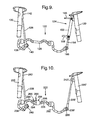
- the present invention is also applicable for use with a vehicle roll control system as shown in Figure 9 .
- the system 122 comprises a torsion bar 126, a first arm 128, and a hydraulic actuator 134.
- the first arm 128 is fixed at one end 138 to one end 140 of the torsion bar 126.
- the other end 142 of the first arm 128 is connected to one of the shock absorbers 120.
- the hydraulic actuator 134 has a piston rod 164 which is fixed to the other end 186 of the torsion bar 126.
- the housing 156 of the actuator 134 is connected to the other shock absorber 120.
- the hydraulic actuator 134 is substantially the same as the actuator 34 described above with reference to Figure 1 to 6 , and has a fluid line 166 connected to a first fluid chamber inside the housing, and another fluid line 168 connected to a second fluid chamber inside the housing.
- the first and second fluid chambers inside the housing 156 are separated by a piston secured to the piston rod 164.
- the fluid lines 166,168 are connected to a hydraulic circuit as shown in Figures 5 and 6 , which is controlled by a control circuit as shown in Figures 5 and 6 , or either of the arrangements shown in Figure 7 or Figure 8 .
- the roll control system 122 is operated in substantially the same manner as that described above with reference to Figures 1 to 6 , Figure 7 , or Figure 8 .
- the system 222 comprises a torsion bar 226, a first arm 228, a second arm 228', and a hydraulic actuator 234.
- the first arm 228 is fixed at one end 238 to one end 240 of the torsion bar 226.
- the other end 242 of the first arm 228 is connected to one of the shock absorbers 220.
- the second arm 228' is fixed at one end 238' to the other end 286 of the torsion bar 226.
- the other end 242' of the second arm 228' is connected to the other shock absorber 220'.
- the torsion bar 226 is split into first and second parts 290,292, respectively.
- the first and second parts 290,292 of the torsion bar 226 have portions 294,296, respectively, which are axially aligned.
- the axially aligned portions 294,296 are connected by a hydraulic actuator 234.
- the hydraulic actuator 23 comprises a cylindrical housing 256 which is connected at one end 239 to the portion 294 of the first part 290 of the torsion bar 226.
- the actuator 234 further comprises a rod 241 positioned inside the housing 256, extending out of the other end 243 of the housing, and connectable to the portion 296 of the second part 292 of the torsion bar 226.
- the rod 241 has an external screw thread 249 adjacent the housing 256.
- Balls 251 are rotatably positioned in hemispherical indentations 253 in the inner surface 255 of the housing 256 adjacent the screw thread 249. The balls 251 extend into the screw thread 249.
- the rod 241 is slidably and rotatably mounted in the housing 256 at the other end 243 by way of a bearing 259 positioned in the other end 243. This arrangement allows the rod 241 to rotate about its longitudinal axis relative to the housing 256, and to slide in an axial direction A relative to the housing.
- a piston chamber 261 is defined inside the housing 256.
- the rod 241 sealing extends into the piston chamber 261 to define a piston rod 264, and a piston 262 is secured to the end of the piston rod inside the piston chamber.
- the piston 262 makes a sealing sliding fit with the housing 256 and divides the chamber 261 into a first fluid chamber 258 and a second fluid chamber 260.
- the first fluid chamber 258 is fluidly connected to fluid line 266, and the second fluid chamber 260 is fluidly connected to fluid line 268.
- the fluid lines 266,268 are connected to a hydraulic circuit as shown in Figures 5 and 6 , which is controlled by a control circuit as shown in Figures 5 and 6 , or either of the arrangements shown in Figure 7 or Figure 8 .
- the roll control system 222 is operated in substantially the same manner as that described above with reference to Figures 1 to 6 , Figure 7 , or Figure 8 .
- the actuator 334 comprises a cylindrical housing 356 which is connected at one end 339 to the portion 294 of the first part 290 of the torsion bar 226.
- the actuator 334 further comprises a rod 341 positioned inside the housing 356, extending out of the other end 343 of the housing, and connectable to the portion 296 of the second part 292 of the torsion bar 226.
- the rod 341 has an external screw thread 349 adjacent the housing 356.
- Balls 351 are rotatably positioned in hemispherical indentations 353 in the inner surface 355 of the housing 356 adjacent the screw thread 349. The balls 351 extend into the screw thread 349.
- the rod 341 is slidably and rotatably mounted in the housing 356 at the other end 343 of the housing by way of a bearing 359 positioned in the other end.
- the rod 341 makes a sliding guiding fit with the inner surface 355 of the housing 356 at its end 341' remote from the second part 292 of the torsion bar 226. This arrangement allows the rod 341 to rotate about its longitudinal axis relative to the housing 356, and to slide in an axial direction A relative to the housing.
- First and second fluid chambers 358,360 are defined inside the housing 356.
- the rod 341 makes a sealing fit with the inner surface 355 of the housing 356 by way of seal 371 to define a piston 362.
- the first fluid chamber 358 is positioned on one side of the piston 362, and the second fluid chamber 360 is positioned on the other side of the piston.
- a seal 369 is positioned adjacent the bearing 359.
- a portion 364 of the rod 341 defines a piston rod which extends through the second fluid chamber 360.
- the first fluid chamber 358 is fluidly connected to fluid line 366, and the second fluid chamber 360 is fluidly connected to fluid line 368.
- the fluid lines 366,368 are fluidly connected with one of the hydraulic circuits shown in Figures 5 to 8 to actuate the actuator 334.
- FIG. 13 A further alternative arrangement of hydraulic actuator 334' is shown in Figure 13 .
- the actuator 334' is substantially the same as the actuator 334 shown in Figure 12 , but without the sliding guiding fit of the free end 341' of the rod 341 with the housing 356.
- the cross-sectional area of the first fluid chamber of each hydraulic actuator described above is substantially double the cross-sectional area of the piston rod of the hydraulic actuator, when considered on a radial basis.
- Such an arrangement provides the same output force from the hydraulic actuator in either direction, using the same fluid pressure and equal amounts of fluid.
- a hydraulic actuator is provided for both the front of the vehicle and the rear of the vehicle, and these hydraulic actuators are controlled in unison. It will be appreciated that the hydraulic actuators may be controlled individually, and in certain cases the portion of the roll control system at the rear of the vehicle may be omitted. Also, the hydraulic actuator for the front of the vehicle may be a different type to the hydraulic actuator for the rear of the vehicle.
- the hydraulic actuator may include a check valve (not shown, but preferably mounted in the piston) which allows flow of hydraulic fluid from the first fluid chamber to the second fluid chamber only when the fluid pressure in the first fluid chamber is greater than the fluid pressure in the second fluid chamber.
- the second fluid chamber can be connected to a reservoir during servicing of the actuator to bleed air from the hydraulic fluid.
- the presence of the check valve reduces the risk of air being sucked into the second fluid chamber should the fluid pressure in the second fluid chamber fall below the fluid pressure in the first fluid chamber, and provides further improvements in ride comfort.
Landscapes
- Engineering & Computer Science (AREA)
- Mechanical Engineering (AREA)
- Vehicle Body Suspensions (AREA)
Claims (15)
- Système de commande de roulis pour un véhicule (10) ayant une paire de roues chacune en rotation sur un axe, comprenant une barre de torsion (24, 22), un premier bras attaché à la barre de torsion à une extrémité du premier bras et susceptible d'être connecté à l'un des axes à l'autre extrémité du premier bras ; un actionneur hydraulique (34) attaché à la barre de torsion ; et des moyens de commande reliés à l'actionneur hydraulique et commandant le fonctionnement de celui-ci lors de la détection d'une condition prédéterminée du véhicule ; dans lequel l'actionneur hydraulique comprend un boîtier, un piston (34) établissant un engagement étanche et à coulissement à l'intérieur du boîtier pour définir une première chambre à fluide (58) et une seconde chambre à fluide (60), et une tige de piston reliée au piston et s'étendant à travers la seconde chambre à fluide (60) et sortant hors du boîtier ; dans lequel les moyens de commande agissent lors de la détection de la condition prédéterminée du véhicule soit pour appliquer sensiblement la même pression de fluide à la première et à la seconde chambre à fluide (58, 60) quand le piston tend à se déplacer dans une première direction pour mettre en extension l'actionneur hydraulique (34), soit pour appliquer une pression de fluide dans la seconde chambre à fluide (60) supérieure à la pression de fluide dans la première chambre à fluide (58) quand le piston tend à se déplacer dans une seconde direction pour comprimer l'actionneur hydraulique (34) ; dans lequel la première chambre à fluide (58) est connectée sur le plan fluidique à un réservoir de fluide (82) par les moyens de commande quand le piston tend à se déplacer dans la seconde direction ; et dans lequel les moyens de commande (70) comprennent une pompe à fluide (60) et une valve directionnelle (184), la pompe étant connectée sur le plan fluidique à la seconde chambre à fluide (60), et la valve directionnelle (184) étant capable de se déplacer entre une première position dans laquelle la première chambre à fluide (58) et la seconde chambre à fluide (60) sont connectées sur le plan fluidique, et une seconde position dans laquelle la première chambre à fluide (58) est connectée sur le plan fluidique au réservoir de fluide (82).
- Système de commande de roulis selon la revendication 1, dans lequel les moyens de commande comprennent un module de commande électronique qui reçoit des signaux dépendant de la condition prédéterminée du véhicule et qui commande le fonctionnement de la pompe à fluide et de la valve directionnelle.
- Système de commande de roulis selon la revendication 1 ou 2, dans lequel l'aire de section transversale de la première chambre à fluide est sensiblement double de l'aire de section transversale de la tige de piston.
- Système de commande de roulis selon l'une quelconque des revendications 1 à 3, dans lequel l'actionneur hydraulique est attaché à la barre de torsion à une extrémité de l'actionneur hydraulique et est susceptible d'être relié à l'autre axe à l'autre extrémité de l'actionneur hydraulique.
- Système de commande de roulis selon la revendication 4, comprenant en outre un second bras monté en rotation sur la barre de torsion à une extrémité du second bras et étant susceptible d'être relié à l'autre axe à l'autre extrémité du second bras ; dans lequel l'actionneur hydraulique commande la rotation du second bras par rapport à la barre de torsion.
- Système de commande de roulis selon la revendication 5, comprenant en outre un bras de levier fixé à la barre de torsion à une extrémité du bras de levier adjacente à ladite une extrémité du second bras, et ayant une extrémité libre à son autre extrémité ; dans lequel l'actionneur hydraulique s'étend entre le second bras et le bras de levier, le boîtier étant relié à un élément parmi le second bras et l'extrémité libre du bras de levier, et la tige de piston étant reliée à l'autre élément parmi le second bras et l'extrémité libre du bras de levier.
- Système de commande de roulis selon la revendication 5, comprenant en outre un bras de levier fixé à une extrémité du bras de levier à ladite autre extrémité du second bras, et ayant une extrémité libre à son autre extrémité, dans lequel l'actionneur hydraulique s'étend entre la barre de torsion et le bras de levier, le boîtier étant relié à un élément parmi la barre de torsion et l'extrémité libre du bras de levier, la tige de piston étant reliée à l'autre élément parmi la barre de torsion et l'extrémité libre du bras de levier.
- Système de commande de roulis selon l'une quelconque des revendications 1 à 3, dans lequel l'actionneur hydraulique est attaché directement à la barre de torsion à une extrémité de l'actionneur hydraulique.
- Système de commande de roulis selon l'une quelconque des revendications 1 à 3, dans lequel l'actionneur hydraulique est attaché à la barre de torsion entre des portions axialement alignées d'une première et d'une seconde partie de la barre de torsion.
- Système de commande de roulis selon la revendication 9, dans lequel le boîtier de l'actionneur hydraulique est relié à une extrémité du boîtier à la première partie de la barre de torsion ; dans lequel la tige de piston est positionnée à l'intérieur du boîtier, est en rotation autour de son axe longitudinal par rapport au boîtier, s'étend hors de l'autre extrémité du boîtier, et est reliée à la seconde partie de la barre de torsion ; l'actionneur hydraulique comprenant en outre un pas de vis externe sur la tige de piston à l'intérieur du boîtier ; et au moins une bille montée en rotation sur le boîtier et s'étendant dans le pas de vis sur la tige de piston en engageant ce pas de vis.
- Système de commande de roulis selon la revendication 10, dans lequel la bille ou chaque bille est montée en rotation dans un creux hémisphérique correspondant dans le boîtier.
- Système de commande de roulis selon la revendication 11, dans lequel la tige de piston définit le piston qui établit un engagement étanche et en coulissement avec le boîtier pour définir la première et la seconde chambre à fluide à l'intérieur du boîtier.
- Système de commande de roulis selon l'une quelconque des revendications 1 à 12, dans lequel les moyens de commande comprennent en outre une valve de commande de pression connectée sur le plan fluidique entre la pompe et le réservoir, la valve de commande de pression étant actionnée pour ajuster la pression du fluide entre une pression minimum prédéterminée et une pression maximum prédéterminée.
- Système de commande de roulis selon l'une quelconque des revendications 1 à 13, dans lequel l'actionneur hydraulique inclut un clapet anti-retour qui permet au fluide de s'écouler depuis la première chambre à fluide vers la seconde chambre à fluide quand la pression du fluide dans la première chambre à fluide dépasse la pression du fluide dans la seconde chambre à fluide.
- Système de commande de roulis selon la revendication 14, dans lequel le clapet anti-retour est monté dans le piston.
Applications Claiming Priority (4)
| Application Number | Priority Date | Filing Date | Title |
|---|---|---|---|
| GB9927933A GB2356606B (en) | 1999-11-26 | 1999-11-26 | Vehile roll control system |
| GB9927933 | 1999-11-26 | ||
| GB0005745 | 2000-03-10 | ||
| GB0005745A GB0005745D0 (en) | 1999-11-26 | 2000-03-10 | Vehicle roll control system |
Publications (3)
| Publication Number | Publication Date |
|---|---|
| EP1103396A2 EP1103396A2 (fr) | 2001-05-30 |
| EP1103396A3 EP1103396A3 (fr) | 2005-06-01 |
| EP1103396B1 true EP1103396B1 (fr) | 2009-04-22 |
Family
ID=26243834
Family Applications (3)
| Application Number | Title | Priority Date | Filing Date |
|---|---|---|---|
| EP00203972A Expired - Lifetime EP1103396B1 (fr) | 1999-11-26 | 2000-11-13 | Système de réglage de roulis de véhicule |
| EP00203973.3A Expired - Lifetime EP1103397B1 (fr) | 1999-11-26 | 2000-11-13 | Vérin hydraulique pour un système de réglage de roulis de véhicule |
| EP00203971A Expired - Lifetime EP1103395B1 (fr) | 1999-11-26 | 2000-11-13 | Système de réglage de roulis de véhicule |
Family Applications After (2)
| Application Number | Title | Priority Date | Filing Date |
|---|---|---|---|
| EP00203973.3A Expired - Lifetime EP1103397B1 (fr) | 1999-11-26 | 2000-11-13 | Vérin hydraulique pour un système de réglage de roulis de véhicule |
| EP00203971A Expired - Lifetime EP1103395B1 (fr) | 1999-11-26 | 2000-11-13 | Système de réglage de roulis de véhicule |
Country Status (2)
| Country | Link |
|---|---|
| US (2) | US6520510B1 (fr) |
| EP (3) | EP1103396B1 (fr) |
Families Citing this family (61)
| Publication number | Priority date | Publication date | Assignee | Title |
|---|---|---|---|---|
| EP1103396B1 (fr) | 1999-11-26 | 2009-04-22 | Delphi Technologies, Inc. | Système de réglage de roulis de véhicule |
| US6851679B2 (en) * | 2002-05-01 | 2005-02-08 | Meritor Light Vehicle Technology, Llc | Simplifed adaptive suspension |
| GB2388086B (en) * | 2002-05-02 | 2005-06-15 | Delphi Tech Inc | Vehicle roll control system |
| WO2003101768A1 (fr) * | 2002-05-31 | 2003-12-11 | Trw Automotive U.S. Llc | Unite de commande integree de systeme de commande active de roulis pour systeme de suspension de vehicule |
| JP2004136814A (ja) * | 2002-10-18 | 2004-05-13 | Kayaba Ind Co Ltd | 捩り剛性力制御装置 |
| JP4155066B2 (ja) * | 2003-03-12 | 2008-09-24 | トヨタ自動車株式会社 | 車両懸架装置 |
| AU2007202912B2 (en) * | 2003-03-12 | 2010-02-25 | Toyota Jidosha Kabushiki Kaisha | Suspension system of vehicle |
| DE20313104U1 (de) * | 2003-08-25 | 2004-01-15 | Trw Fahrwerksysteme Gmbh & Co Kg | Baugruppe für ein Fahrwerkstabilisierungssystem |
| US7287759B2 (en) * | 2003-09-30 | 2007-10-30 | Kabushiki Kaisha Hitachi Seisakusho | Stabilizer device |
| US7270336B2 (en) | 2003-11-12 | 2007-09-18 | Hiromichi Fujimori | Adjustable stabilizer bar assembly |
| JP2005178472A (ja) * | 2003-12-17 | 2005-07-07 | Nissan Motor Co Ltd | 車両用スタビライザ装置 |
| WO2005070711A1 (fr) * | 2004-01-21 | 2005-08-04 | Continental Teves Ag & Co. Ohg | Systeme de stabilisation d'un vehicule |
| GB0410355D0 (en) * | 2004-05-10 | 2004-06-09 | Delphi Tech Inc | Vehicle roll control system |
| GB0410357D0 (en) | 2004-05-10 | 2004-06-09 | Delphi Tech Inc | Vehicle roll control system |
| DE102004025807B4 (de) * | 2004-05-24 | 2009-01-22 | Zf Friedrichshafen Ag | Stabilisatoranordnung für ein Kraftfahrzeug |
| US7475895B2 (en) * | 2004-06-15 | 2009-01-13 | Delphi Technologies, Inc. | Hydraulic circuit for a stabilizer bar |
| DE202004013017U1 (de) * | 2004-08-19 | 2004-12-30 | Trw Automotive Gmbh | Wankregelungsstellantrieb |
| KR101001267B1 (ko) * | 2004-11-22 | 2010-12-14 | 주식회사 만도 | 에어 서스펜션 및 전자제어 서스펜션 장치 |
| DE102005010239B4 (de) * | 2005-03-05 | 2008-07-10 | Zf Friedrichshafen Ag | Federungssystem für Kraftfahrzeuge |
| DE102005028327A1 (de) * | 2005-06-18 | 2006-12-21 | Daimlerchrysler Ag | Aktive hydraulische Wankstabilisierung mit einer Zylinderkolbeneinheit und Kolbenventilen |
| JP4193819B2 (ja) * | 2005-06-27 | 2008-12-10 | トヨタ自動車株式会社 | 車両用懸架装置 |
| US7494132B2 (en) * | 2005-06-28 | 2009-02-24 | Arvinmeritor Technology, Llc | Roll control actuator with piston assembly |
| US7487973B1 (en) | 2005-08-24 | 2009-02-10 | Kelsey-Hayes Company | Multi-channel hydraulic control unit for an active vehicle suspension |
| US7360771B2 (en) * | 2005-10-04 | 2008-04-22 | Arvinmeritor Technology, Llc | Roll control actuator with rotary mechanism |
| DE602006017790D1 (de) | 2006-01-19 | 2010-12-09 | Delphi Tech Inc | Aktive Radaufhängung für ein Kraftfahrzeug mit Steuerung zur Eingrenzung der Rollbewegung |
| US7543832B2 (en) * | 2006-01-26 | 2009-06-09 | Polaris Industries Inc. | Variable rate stabilizer bar |
| DE102006012173A1 (de) * | 2006-03-16 | 2007-09-20 | Trw Automotive Gmbh | Fahrwerksystem |
| US7665742B2 (en) * | 2006-05-12 | 2010-02-23 | Haerr Timothy A | Vehicle hydraulic system |
| EP1862338A1 (fr) * | 2006-05-29 | 2007-12-05 | Nederlandse Organisatie voor Toegepast-Natuuurwetenschappelijk Onderzoek TNO | Système de suspension pour un véhicule |
| GB0618178D0 (en) | 2006-09-14 | 2006-10-25 | Delphi Tech Inc | Vehicle roll control system |
| GB0618333D0 (en) * | 2006-09-19 | 2006-10-25 | Delphi Tech Inc | Hydraulic control circuit |
| JP2010522112A (ja) * | 2007-03-23 | 2010-07-01 | アーヴィンメリター テクノロジー エルエルスィー | ロール制御デバイス |
| GB0714103D0 (en) | 2007-07-19 | 2007-08-29 | Delphi Tech Inc | Vehicle roll control system |
| GB0714102D0 (en) * | 2007-07-19 | 2007-08-29 | Delphi Tech Inc | Vehicle roll control |
| US7798508B2 (en) * | 2008-01-04 | 2010-09-21 | Altair Engineering, Inc. | Active stabilizer bar system for a vehicle chassis |
| FR2927021A1 (fr) * | 2008-02-04 | 2009-08-07 | Renault Sas | Systeme anti-roulis pour vehicule automobile. |
| WO2010078471A1 (fr) * | 2008-12-30 | 2010-07-08 | Darco Trust | Système de suspension de véhicule |
| US8616351B2 (en) | 2009-10-06 | 2013-12-31 | Tenneco Automotive Operating Company Inc. | Damper with digital valve |
| US9217483B2 (en) | 2013-02-28 | 2015-12-22 | Tenneco Automotive Operating Company Inc. | Valve switching controls for adjustable damper |
| WO2014134500A1 (fr) | 2013-02-28 | 2014-09-04 | Tenneco Automotive Operating Company Inc. | Amortisseur avec électronique intégrée |
| US9884533B2 (en) | 2013-02-28 | 2018-02-06 | Tenneco Automotive Operating Company Inc. | Autonomous control damper |
| US9879746B2 (en) | 2013-03-15 | 2018-01-30 | Tenneco Automotive Operating Company Inc. | Rod guide system and method with multiple solenoid valve cartridges and multiple pressure regulated valve assemblies |
| US9879748B2 (en) | 2013-03-15 | 2018-01-30 | Tenneco Automotive Operating Company Inc. | Two position valve with face seal and pressure relief port |
| EP2971847A4 (fr) | 2013-03-15 | 2016-12-21 | Tenneco Automotive Operating Co Inc | Ensemble guide de tige comportant un ensemble soupape à éléments multiples |
| US9163691B2 (en) | 2013-03-15 | 2015-10-20 | Tenneco Automotive Operating Company Inc. | Rod guide arrangement for electronically controlled valve applications |
| US20160324243A1 (en) * | 2013-09-11 | 2016-11-10 | Davis Graham Jackson | Apparatus for Securing a Mask to a Wearer |
| US9751374B2 (en) * | 2014-09-22 | 2017-09-05 | GM Global Technology Operations LLC | Vehicle and a height adjustment system for the vehicle |
| DE102015205045A1 (de) * | 2015-03-20 | 2016-09-22 | Zf Friedrichshafen Ag | Aktiver Stabilisator für eine Fahrerkabine eines Kraftfahrzeugs |
| US10588233B2 (en) | 2017-06-06 | 2020-03-10 | Tenneco Automotive Operating Company Inc. | Damper with printed circuit board carrier |
| US10479160B2 (en) | 2017-06-06 | 2019-11-19 | Tenneco Automotive Operating Company Inc. | Damper with printed circuit board carrier |
| EP3678667A4 (fr) | 2017-09-08 | 2021-10-20 | Eleszto Genetika, Inc. | Micro-organismes et méthodes pour la fermentation d'alcaloïdes de benzylisoquinoline |
| FR3070901B1 (fr) * | 2017-09-12 | 2021-03-12 | Psa Automobiles Sa | Dispositif anti-devers a moyens d’action pilotes par un circuit de controle hydraulique, pour un train de vehicule automobile |
| US11173767B2 (en) * | 2019-10-22 | 2021-11-16 | Christopher Cox Creative | Hydraulic anti-roll bar link |
| US11634003B2 (en) | 2020-12-17 | 2023-04-25 | Fox Factory, Inc. | Automated control system for an electronically controlled sway bar link |
| FR3120331A1 (fr) | 2021-03-02 | 2022-09-09 | Renault S.A.S | Système suspension active avec mécanisme planétaire différentiel |
| US12311720B2 (en) | 2022-02-23 | 2025-05-27 | Fox Factory, Inc. | Hydraulic cross-linked suspension |
| US12502923B2 (en) | 2022-02-23 | 2025-12-23 | Fox Factory, Inc. | Hydraulic cross-linked suspension |
| US12319109B2 (en) | 2023-03-09 | 2025-06-03 | Schaeffler Technologies AG & Co. KG | Stabilizer bar hydraulic disconnect |
| US12070984B1 (en) | 2023-07-14 | 2024-08-27 | Schaeffler Technologies AG & Co. KG | Stabilizer bar disconnect |
| EP4653284A1 (fr) * | 2024-05-24 | 2025-11-26 | ALSTOM Holdings | Système de suspension pour un bogie et bogie et véhicule associés |
| US12522042B1 (en) | 2024-10-24 | 2026-01-13 | Fox Factory, Inc. | Linked gas chambers for e-sway disconnect |
Family Cites Families (22)
| Publication number | Priority date | Publication date | Assignee | Title |
|---|---|---|---|---|
| US3147671A (en) * | 1962-12-04 | 1964-09-08 | Gen Motors Corp | Hydraulic actuator |
| JPS60169314A (ja) * | 1984-02-14 | 1985-09-02 | Nissan Motor Co Ltd | 車両用スタビライザ |
| JPH0717142B2 (ja) * | 1987-11-19 | 1995-03-01 | 日本電装株式会社 | スタビライザ制御装置 |
| DE3818188A1 (de) * | 1988-05-28 | 1989-12-07 | Daimler Benz Ag | Aktives federungssystem |
| GB8906229D0 (en) | 1989-03-17 | 1989-05-04 | Gkn Technology Ltd | Vehicle suspension systems |
| JPH035224A (ja) * | 1989-05-31 | 1991-01-11 | Chuo Spring Co Ltd | 車輌用スタビライザ装置 |
| US5020826A (en) * | 1989-11-06 | 1991-06-04 | Southwest Research Institute | Vehicle suspension system |
| IT1245804B (it) | 1991-05-06 | 1994-10-18 | Fiat Auto Spa | Sistema per il controllo del carico di una barra stabilizzatrice anti-rollio associata ad una sospensione a ruote indipendenti di un autoveicolo. |
| GB9213178D0 (en) * | 1992-06-22 | 1992-08-05 | Lotus Car | Vehicle suspension system |
| US5362094A (en) * | 1993-06-09 | 1994-11-08 | General Motors Corporation | Hydraulically controlled stabilizer bar system |
| DE4337765A1 (de) * | 1993-11-05 | 1995-05-11 | Fichtel & Sachs Ag | Zweikreishydrauliksystem für eine aktive Fahrwerksregelung zur Unterdrückung der Rollbewegung eines Kraftfahrzeuges |
| GB9324551D0 (en) * | 1993-11-30 | 1994-01-19 | Acg France | Vehicle roll control system |
| US5529324A (en) * | 1994-08-15 | 1996-06-25 | Kelsey-Hayes Company | System and method for vehicle roll control |
| US5630623A (en) * | 1994-08-15 | 1997-05-20 | Kelsey Hayes | Vehicle roll control system |
| US5549328A (en) * | 1995-01-17 | 1996-08-27 | Gabriel Ride Control Products, Inc. | Roll control system |
| GB2304652B (en) | 1995-08-24 | 1999-08-18 | Delphi France Automotive Sys | Vehicle roll control system |
| US5749596A (en) * | 1996-09-16 | 1998-05-12 | General Motors Corporation | Latchable stabilizer bar actuator |
| GB9626045D0 (en) * | 1996-12-14 | 1997-01-29 | Rover Group | A vehicle roll stabilising system |
| DE19735248C1 (de) * | 1997-08-14 | 1999-02-04 | Mannesmann Sachs Ag | Kolben für ein Kolben-Zylinderaggregat |
| DE19755994C2 (de) * | 1997-12-17 | 2003-02-20 | Thyssen Krupp Bilstein Gmbh | Kolben für einen hydraulischen Schwingungsdämpfer |
| GB9812274D0 (en) * | 1998-06-09 | 1998-08-05 | Rover Group | Hydraulic control systems |
| EP1103396B1 (fr) | 1999-11-26 | 2009-04-22 | Delphi Technologies, Inc. | Système de réglage de roulis de véhicule |
-
2000
- 2000-11-13 EP EP00203972A patent/EP1103396B1/fr not_active Expired - Lifetime
- 2000-11-13 EP EP00203973.3A patent/EP1103397B1/fr not_active Expired - Lifetime
- 2000-11-13 EP EP00203971A patent/EP1103395B1/fr not_active Expired - Lifetime
- 2000-11-22 US US09/721,459 patent/US6520510B1/en not_active Expired - Lifetime
- 2000-11-22 US US09/721,446 patent/US6533294B1/en not_active Expired - Lifetime
Also Published As
| Publication number | Publication date |
|---|---|
| EP1103397B1 (fr) | 2014-07-02 |
| EP1103397A3 (fr) | 2005-06-01 |
| EP1103396A3 (fr) | 2005-06-01 |
| EP1103395B1 (fr) | 2009-05-06 |
| EP1103397A2 (fr) | 2001-05-30 |
| US6520510B1 (en) | 2003-02-18 |
| EP1103395A3 (fr) | 2005-06-01 |
| US6533294B1 (en) | 2003-03-18 |
| EP1103395A2 (fr) | 2001-05-30 |
| EP1103396A2 (fr) | 2001-05-30 |
Similar Documents
| Publication | Publication Date | Title |
|---|---|---|
| US6520510B1 (en) | Vehicle roll control system | |
| EP1503913B1 (fr) | Systeme de commande de roulis d'un vehicule | |
| US7862052B2 (en) | Vehicle roll control system | |
| US7694984B2 (en) | Vehicle roll control system | |
| US5597180A (en) | Vehicle roll control apparatus | |
| EP1379399B1 (fr) | Systeme de commande de roulis de vehicule | |
| EP3461663B1 (fr) | Liaison d'amortissement à barre stabilisatrice commandée électroniquement | |
| US5431431A (en) | Vehicle roll control system | |
| EP2017101B1 (fr) | Système de régulation de roulis de véhicule | |
| EP0783986A2 (fr) | Système de réglage de roulis de véhicule | |
| US8065056B2 (en) | Vehicle roll control system | |
| EP1902875B1 (fr) | Circuit de contrôle hydraulique | |
| EP1747106A1 (fr) | Systeme de controle de roulis de vehicule | |
| GB2356606A (en) | Vehicle roll control system having an adjustable torsion bar |
Legal Events
| Date | Code | Title | Description |
|---|---|---|---|
| PUAI | Public reference made under article 153(3) epc to a published international application that has entered the european phase |
Free format text: ORIGINAL CODE: 0009012 |
|
| AK | Designated contracting states |
Kind code of ref document: A2 Designated state(s): AT BE CH CY DE DK ES FI FR GB GR IE IT LI LU MC NL PT SE TR |
|
| AX | Request for extension of the european patent |
Free format text: AL;LT;LV;MK;RO;SI |
|
| PUAL | Search report despatched |
Free format text: ORIGINAL CODE: 0009013 |
|
| AK | Designated contracting states |
Kind code of ref document: A3 Designated state(s): AT BE CH CY DE DK ES FI FR GB GR IE IT LI LU MC NL PT SE TR |
|
| AX | Request for extension of the european patent |
Extension state: AL LT LV MK RO SI |
|
| RIC1 | Information provided on ipc code assigned before grant |
Ipc: 7B 60G 21/067 B Ipc: 7B 60G 17/015 B Ipc: 7B 60G 21/073 B Ipc: 7B 60G 21/055 A |
|
| 17P | Request for examination filed |
Effective date: 20051201 |
|
| AKX | Designation fees paid |
Designated state(s): DE FR GB |
|
| GRAP | Despatch of communication of intention to grant a patent |
Free format text: ORIGINAL CODE: EPIDOSNIGR1 |
|
| GRAS | Grant fee paid |
Free format text: ORIGINAL CODE: EPIDOSNIGR3 |
|
| GRAA | (expected) grant |
Free format text: ORIGINAL CODE: 0009210 |
|
| AK | Designated contracting states |
Kind code of ref document: B1 Designated state(s): DE FR GB |
|
| REG | Reference to a national code |
Ref country code: GB Ref legal event code: FG4D |
|
| REF | Corresponds to: |
Ref document number: 60042053 Country of ref document: DE Date of ref document: 20090604 Kind code of ref document: P |
|
| PLBE | No opposition filed within time limit |
Free format text: ORIGINAL CODE: 0009261 |
|
| STAA | Information on the status of an ep patent application or granted ep patent |
Free format text: STATUS: NO OPPOSITION FILED WITHIN TIME LIMIT |
|
| 26N | No opposition filed |
Effective date: 20100125 |
|
| REG | Reference to a national code |
Ref country code: FR Ref legal event code: PLFP Year of fee payment: 16 |
|
| REG | Reference to a national code |
Ref country code: FR Ref legal event code: PLFP Year of fee payment: 17 |
|
| REG | Reference to a national code |
Ref country code: GB Ref legal event code: 732E Free format text: REGISTERED BETWEEN 20170727 AND 20170802 |
|
| REG | Reference to a national code |
Ref country code: FR Ref legal event code: PLFP Year of fee payment: 18 |
|
| REG | Reference to a national code |
Ref country code: FR Ref legal event code: CA Effective date: 20171124 Ref country code: FR Ref legal event code: TP Owner name: BWI COMPANY LIMITED S.A., LU Effective date: 20171124 |
|
| PGFP | Annual fee paid to national office [announced via postgrant information from national office to epo] |
Ref country code: DE Payment date: 20171108 Year of fee payment: 18 Ref country code: FR Payment date: 20171012 Year of fee payment: 18 |
|
| PGFP | Annual fee paid to national office [announced via postgrant information from national office to epo] |
Ref country code: GB Payment date: 20171108 Year of fee payment: 18 |
|
| REG | Reference to a national code |
Ref country code: DE Ref legal event code: R119 Ref document number: 60042053 Country of ref document: DE |
|
| GBPC | Gb: european patent ceased through non-payment of renewal fee |
Effective date: 20181113 |
|
| PG25 | Lapsed in a contracting state [announced via postgrant information from national office to epo] |
Ref country code: DE Free format text: LAPSE BECAUSE OF NON-PAYMENT OF DUE FEES Effective date: 20190601 Ref country code: FR Free format text: LAPSE BECAUSE OF NON-PAYMENT OF DUE FEES Effective date: 20181130 |
|
| PG25 | Lapsed in a contracting state [announced via postgrant information from national office to epo] |
Ref country code: GB Free format text: LAPSE BECAUSE OF NON-PAYMENT OF DUE FEES Effective date: 20181113 |
|
| REG | Reference to a national code |
Ref country code: DE Ref legal event code: R081 Ref document number: 60042053 Country of ref document: DE Owner name: BWI COMPANY LIMITED S.A., LU Free format text: FORMER OWNER: DELPHI TECHNOLOGIES, INC., TROY, MICH., US Ref country code: DE Ref legal event code: R082 Ref document number: 60042053 Country of ref document: DE |