EP1103410A2 - Ensemble d'ancrage - Google Patents
Ensemble d'ancrage Download PDFInfo
- Publication number
- EP1103410A2 EP1103410A2 EP00310439A EP00310439A EP1103410A2 EP 1103410 A2 EP1103410 A2 EP 1103410A2 EP 00310439 A EP00310439 A EP 00310439A EP 00310439 A EP00310439 A EP 00310439A EP 1103410 A2 EP1103410 A2 EP 1103410A2
- Authority
- EP
- European Patent Office
- Prior art keywords
- anchor
- anchor assembly
- hooks
- lock unit
- lock
- Prior art date
- Legal status (The legal status is an assumption and is not a legal conclusion. Google has not performed a legal analysis and makes no representation as to the accuracy of the status listed.)
- Withdrawn
Links
- 238000003466 welding Methods 0.000 claims description 7
- 230000000717 retained effect Effects 0.000 claims description 6
- 239000011248 coating agent Substances 0.000 description 1
- 238000000576 coating method Methods 0.000 description 1
- 230000001419 dependent effect Effects 0.000 description 1
- 230000014759 maintenance of location Effects 0.000 description 1
- 238000000034 method Methods 0.000 description 1
Images



Classifications
-
- B—PERFORMING OPERATIONS; TRANSPORTING
- B60—VEHICLES IN GENERAL
- B60N—SEATS SPECIALLY ADAPTED FOR VEHICLES; VEHICLE PASSENGER ACCOMMODATION NOT OTHERWISE PROVIDED FOR
- B60N2/00—Seats specially adapted for vehicles; Arrangement or mounting of seats in vehicles
- B60N2/005—Arrangement or mounting of seats in vehicles, e.g. dismountable auxiliary seats
- B60N2/015—Attaching seats directly to vehicle chassis
- B60N2/01508—Attaching seats directly to vehicle chassis using quick release attachments
- B60N2/01516—Attaching seats directly to vehicle chassis using quick release attachments with locking mechanisms
Definitions
- the invention relates to an anchor assembly, in particular, but not exclusively, an anchor assembly for releaseably connecting a vehicle seat to the floor of a vehicle body.
- An aim of the invention is to provide an anchor assembly for a vehicle seat that enables the seat to be slidably adjusted between predetermined fixed positions. It is also an aim of the invention to provide an anchor assembly that enables a vehicle seat to be releaseably connected to the floor of a vehicle body, so allowing the seat to be tilted or folded, or removed completely from the floor of the vehicle.
- an anchor assembly suitable for releaseably and adjustably securing a vehicle seat to the floor of a vehicle, comprising:
- the anchor assembly of the invention provides a mechanism for securing a vehicle seat to the floor of a vehicle in such a manner that the position of the seat may be adjusted, and it may be secured in at least one predetermined adjustment position.
- the anchor assembly also allows the seat to be detached or removed from the floor of the vehicle when required.
- the lock unit that in use is secured to the base of the vehicle seat may be provided with at least two pivotally mounted lock members. In use, such lock members are arranged to co-operate with the anchor member in the anchor unit.
- the anchor member in the anchor unit may be provided with one or a number of recesses.
- the lock unit includes at least two lock members, at least one of these lock members may be pivotal in and out of engagement with the or a recess on the anchor member. This allows the lock unit to be releaseably secured in at least one predetermined adjustment position on the anchor member.
- At least one of the lock members may co-operate with the anchor member to retain the lock unit in co-operation with the anchor member during sliding movement of the lock unit along the anchor member, unless the lock unit is located at a predetermined release position.
- the anchor member is preferably an elongate rod that may be provided with a plurality of recesses equidistantly spaced along the length of the elongate rod.
- the anchor unit that in use is secured to the floor of the vehicle may also include a generally U-shaped elongate channel member provided with a base and upstanding walls.
- the anchor member in the form of an elongate bar may be located so that it extends longitudinally through and along the interior region of the elongate channel member, spaced from the channel's base and upstanding walls.
- the elongate channel member may be secured to the floor of a vehicle by any suitable means.
- Such attachment means include bolts, rivets and/or welding.
- the elongate rod may be secured to the floor of a vehicle by two legs. These legs may be fixedly secured to the floor of the vehicle by means such as bolts or welding.
- At least one lock member may be retained in co-operation with the anchor member during sliding movement of the lock unit along the anchor member in the form of an elongate bar, by at least one upstanding wall of the elongate channel member. In a further embodiment, all of the lock members may be retained in co-operation with the elongate bar by at least one of the upstanding walls of the elongate channel member.
- a predetermined release position may be defined by a cutaway portion in an upstanding wall of the elongate channel member that otherwise retains at least one of the lock members in co-operation with the elongate rod.
- a cutaway portion allows all of the lock members to be pivoted out of co-operation with the elongate rod, releasing the lock member, and hence detaching the vehicle seat to which the lock unit is attached from the floor of the vehicle.
- the upstanding walls of the elongate channel member may be provided with outwardly extending flanges. These flanges provide a bearing support upon which a vehicle seat can be slidably seated.
- the lock unit is provided with at least two lock members, where each lock member is in the form of a hook. These hooks may be mounted on a pivot shaft, the pivot shaft being arranged to lie parallel to the anchor member.
- At least one of the hooks that is releasably engageable within the or a recess on the anchor member, may be provided with a projection so that when the hook is pivoted into engagement with the or a recess the projection engages within the recess.
- the hooks may also be coupled together.
- One of the hooks may include a projection that projects outwardly from a side face of the hook that is adjacent to a side face of another hook, and extends through an arcuate slot through the or each other hook.
- the arcuate slot allows a certain amount of free play in the movement of at least one of the hooks, without causing the at least one other hook to move.
- the lock unit includes four lock members, each in the form of a hook, pivotally mounted on a pivotal axis within a lock unit body housing.
- the lock unit body housing may include hook stops that determine the maximum amount of rotation of the hooks about the pivotal axis.
- the hooks may be spring biased relative to each other.
- a spring bias may be provided by a torsion spring.
- a face of each of the relevant hooks that co-operates with the anchor member may be provided with a negative taper angle.
- the hooks may be mounted on a pivot shaft that has a cross-sectional shape that corresponds to the shape of the apertures through which the pivot shaft extends in two of the hooks.
- the shape of the apertures through which the pivot shaft extends in the other two hooks is preferably circular.
- the cross-sectional shape of the pivot shaft and the correspondingly shaped apertures in the hooks are preferably generally D-shaped. Due to the relative shapes of the pivot shaft's cross-section and the apertures in the hooks, rotation of the pivot shaft causes the two hooks with correspondingly shaped apertures to rotate, whilst the other two hooks remain unaffected.
- a cable puller may be located on the pivot shaft to provide means to rotate the pivot shaft and so pivot the two hooks with correspondingly shaped apertures in and out of engagement with a recess on the anchor member.
- a cable may be attached directly to the other two hooks to provide means to pivot them about the pivot shaft.
- An anchor assembly 10 includes an anchor unit 12 that in use is fixed to the floor 14 of a vehicle body, and a lock unit 30 that in use is mounted on the underside of a vehicle seat.
- FIG. 1 An anchor unit 12 according to a first embodiment of the invention is shown in Figure 1.
- the anchor unit 12 shown in this figure includes a generally U-shaped, elongate channel member 16 having a base 17 and opposed upstanding walls 18, 19.
- the elongate channel member 16 is fixedly secured to the floor 14 of a vehicle. This is preferably achieved by securing the base 17 to the floor 14 by any convenient fixing technique.
- the base 17 may be secured by bolt, rivets and/or welding.
- the anchor unit 12 also includes an anchor member 20.
- the anchor member 20 is located within the elongate channel member 16 and is also fixedly connected to the floor 14.
- the anchor member 20 has an elongate body portion 21 that is secured at each end to the floor 14 via legs 22.
- the legs 22 can be fixedly secured to the floor 14 by any suitable fixing means such as bolts or welding.
- the legs 22 not only fixedly secure the body portion 21 to the floor 14, but they also position the body portion 21 such that it extends longitudinally along an interior region of the elongate channel member 16, being spaced from the base 17 and the side walls 18, 19.
- Each of the upstanding walls 18, 19 of the elongate channel member 16 is provided with an outwardly extending support flange 25, 26.
- These flanges 25, 26 are preferably provided on the upper edges of the upstanding walls 18, 19 to provide a bearing support surface upon which a vehicle seat (not shown) may be slidingly seated. If desired, the upper surfaces of each of the flanges 25, 26 may be provided with a low friction coating to facilitate sliding movement of the seat.
- a lock unit 30 is shown in Figures 2 and 3.
- the lock unit 30 includes a stop hook 31 and a safety hook 32 that are preferably pivotally mounted side-by-side on a common pivot shaft 33.
- the pivot shaft 33 is secured to the vehicle seat.
- both the stop hook 31 and the safety hook 32 are located in active rotary positions. In these rotary positions both the stop hook 31 and the safety hook 32 co-operate with the body portion 21.
- the stop unit 30 (and hence the seat to which it is attached) is prevented from moving longitudinally along the body portion 21 as a projection 36 provided on the stop hook 31 is engaged within one of a number of recesses 38 provided on the body portion 21.
- a predetermined number of recesses 38 are provided at equally spaced intervals on the underside of the body portion 21.
- the safety hook 32 is a similar shape to the stop hook 31, except that it is not provided with a projection corresponding to the projection 36 provided on the stop hook 31. This means that the safety hook 32 co-operates with the body portion 21, without engaging within any of the recesses 38.
- the safety hook 32 is provided with a projection 40 on a surface that abuts an adjacent surface of the stop hook 31. This projection 40 couples the stop hook 31 and the safety hook 32 together, by extending through an arcuate slot 42 provided through the stop hook 31.
- the safety hook 32 In the position shown in Figure 5, the safety hook 32 is in the same position as in Figures 2 and 4, and the stop hook 31 is located in an unlocked position. Due to the unlocked position of the stop hook 31, and the nature of co-operation between the safety hook 32 and the body portion 21, the lock unit 30 is free to move longitudinally in either direction along the body portion 21. The position of a safety hook 32 also ensures that the lock unit 30 can not be removed in the upward direction, away from the body portion 21.
- the stop hook 31 To unlock the stop hook 31, it is rotated about the pivot shaft 33 a distance sufficient to disengage the projection 36 from the relevant recess 38 in the body portion 21.
- the amount of rotation of the stop hook 31 is controlled by the adjacent upstanding wall 18 of the elongate channel member 16.
- the position of the upstanding wall 18 is such that it prevents the stop hook 31 completely disengaging from the body portion 21.
- the arcuate slot 42 provided in the stop hook 31 ensures that rotation of the stop hook 31 about the pivot shaft 33, into an unlocked position, does not cause the safety hook 32 to rotate as well.
- the safety hook 32 remains in the same active rotary position, and, whilst allowing longitudinal movement, it does not allow the lock unit 30 to be removed in the upward direction, away from the body portion 21.
- the safety hook 32 would be prevented from moving out of co-operation with the body portion 21 by the adjacent upstanding wall 18 of the elongate channel member 16. As with the stop hook 31, the adjacent side wall 18 would restrict the amount of rotation of the safety hook 32 about the pivot shaft 33.
- the lock unit 30 can be locked into position to prevent further longitudinal movement.
- the lock unit 30 is locked into position by rotating the stop hook 31 around the pivot shaft 33 so that the projection 36 engages in a suitable recess 38 on the body portion 21.
- both the stop hook 31 and the safety hook 32 are located in release positions.
- the lock unit 30 can be removed in the upward direction, away from the body portion 21.
- the stop hook 31 and the safety hook 32 can only be moved into these release positions when they are positioned at a predetermined point along the body portion 21. At this predetermined point, a portion of the upstanding wall 18 of the elongate channel member 16 is cut away.
- the predetermined point to allow the release of the lock unit from the body portion 21 is at a far end of the body portion 21.
- the safety hook 32 can be rotated about the pivot shaft 33.
- the degree of rotation of the safety hook 32 is not restricted by the adjacent channel wall 18 as described earlier in the rotation of the stop hook 31.
- the safety hook 32 can hence be rotated a sufficient distance about the pivot shaft 33 to release the safety hook 32 from the body portion 21.
- the projection 40 Whilst the safety hook 32 is rotated about the pivot shaft 33, the projection 40 moves along the arcuate slot 42 in the stop hook 31. When the projection reaches the end of the slot 42, continued rotation of the safety hook 32 causes the stop hook 31 to rotate as well.
- the two hooks 31, 32 of the lock unit 30 can thus be disengaged from the body portion 21, releasing the lock unit 30, and the seat to which it is attached, from the floor 14 of the vehicle.
- FIG. 7 An anchor assembly 110 according to a second embodiment of the invention is shown in Figure 7.
- the anchor assembly 110 includes an anchor unit 112 and a lock unit 130.
- the anchor unit 112 includes a generally U-shaped elongate channel member 116 having a base 117 and upstanding walls 118, 119.
- the elongate channel member 116 can be fixedly connected to the floor 114 of a vehicle by any convenient fixing means.
- fixing means may include bolts, rivets and/or welding.
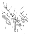
- the anchor unit 112 also includes an anchor member 120 located so that it extends longitudinally through and along the interior region of the elongate channel member 116, being spaced from the base 117 and upstanding walls 118, 119.
- the anchor member 120 shown in Figure 7 is provided with a number of equidistantly spaced recesses 138 extending circumferentially about the anchor member 120.
- the lock unit 130 that is shown in Figure 7 includes an outer housing 128, through which a pivot shaft 136 having a generally D-shaped cross-section extends.
- the lock unit 130 according to this embodiment of the invention is shown more clearly in Figure 8.
- the lock unit 130 includes two stop hooks 131, 132 and two safety hooks 133, 134. These stop and safety hooks 131-134 are pivotally mounted on the pivot shaft 136.
- the apertures 131a, 132a through which the pivot shaft 136 extends in the stop hooks 131, 132 is of generally the same shape as the cross-section of the pivot shaft 136.
- the apertures 133a, 134a through which the pivot shaft extends in the safety hooks 133, 134 is generally circular.
- the stop and safety hooks 131-134 are mounted on the pivot shaft 136 so that the two safety hooks 133, 134 are side-by-side, 'sandwiched' between the two stop hooks 131, 132.
- the orientation of the stop hooks 131, 132 is opposite to the orientation of the safety hooks 133, 134.
- the stop hooks 131, 132 engage about an opposite side of the anchor member 120 to the safety hooks 133, 134.
- a torsion spring 150 is mounted on the pivot shaft 136 along with the stop and safety hooks 131-134. In use a first end of the torsion spring 150 is engaged behind a spring location peg 140 that extends through top corners of the stop hooks 131, 132. The other end of the torsion spring is located behind a spring location peg 142 that extends through corresponding top corners of the safety hooks 133, 134.
- the spring bias of the torsion spring 150 urges the stop and safety hooks 131-134 into engagement around the anchor member 120.
- the outer housing 128 of the lock unit 130 positions over the stop and safety hooks 131-134, the pivot shaft 136 extending through circular apertures 128a, 128b on either side of the housing 128.
- Recesses 142, 144 are but into either side of the outer housing 128 so that in use, the outer housing 128 straddles the anchor member 120.
- a cable puller 146 is shown in Figure 8 that can be used to attach a cable to the pivot shaft 136.
- This cable puller 146 is mounted on the pivot shaft 136 on the outside of a front face of the outer housing 128.
- the aperture 146a through which the pivot shaft extends in this cable puller 146 is generally D-shaped to ensure that when a cable attached to the cable puller 146 is pulled, it causes the pivot shaft 136 to rotate which in turn causes the stop hooks 131, 132 to rotate.
- the cross-section of the pivot shaft 136, the apertures 131a, 132a in the stop hooks 131, 132 and the aperture 146a in the cable puller 146 need not be D-shaped, but could be any suitable shape that allows a driving force to be transferred to each of the components, without affecting the safety hooks 133, 134.
- the safety hooks 133, 134 are a similar shape to the stop hooks 131, 132, except that the safety hooks 133, 134 are shaped to provide a clearance between them and the recesses 138 on the anchor member 120.
- the lock unit 130 is free to move in either direction along the anchor member 120.
- the lock unit 130 is prevented from being removed from the anchor member 120 by the safety hooks 133, 134 that still co-operate with the anchor member 120.
- the safety hooks 133, 134 are prevented from disengaging from the anchor member 120 by the position of the channel wall 118 relative to the safety hooks 133, 134.
- the channel wall 118 prevents the safety hooks 133, 134 from rotating a sufficient distance around the pivot shaft 136 to allow the safety hooks 133, 134 to disengage from the anchor member 120.
- a negative taper angle may be provided on faces of the safety hooks 133, 134, that slidably engage with the outermost surfaces of the anchor member 120. This negative taper angle helps to prevent the safety hooks 133, 134 from disengaging with the anchor member 120.
- the lock unit 130 When the lock unit 130 has been moved along the anchor member 120 to a desired position, the lock unit 130 can be locked into position by releasing the stop hooks 131, 132.
- the stop hooks 131, 132 and the track triggers are released by releasing the cable attached to the cable puller 150.
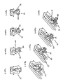
- the stop hooks 131, 132 hence return to a locked position in which they each engage within one of the recesses 138, as shown in Figures 12 and 16.
- the lock unit 130 can be released from the anchor member 120. This is because the lock unit 130 has been moved along the anchor member 120 to a point that is adjacent a cut away portion 152 of the channel wall 18.
- the cable attached to the cable puller 146 can be pulled to rotate the stop hooks 131, 132 out of engagement with the anchor member 120.
- a cable attached directly to the safety hooks can also be pulled to rotate the safety hooks 133, 134 about the pivot shaft 136, and out of engagement with the anchor member 120.
- the safety hooks 133, 134 are not restricted by the channel wall 18, due to the cut away portion 152.
- the maximum distance of rotation of the stop and safety hooks 131-134 is however restricted by hook stops 154, 156 that are engaged through the sides of the outer housing 128 of the lock unit 130.
- the maximum distance is large enough to allow the lock unit 130 to be lifted away from the anchor unit 112, as in Figures 19 and 23.
- the seat to which the lock unit 130 is secured can be released from the floor 114 of the vehicle.
- the lock unit 130 needs to be brought back into contact with the anchor member 120 at the same point along the anchor member 120 as release was achieved. This position is shown in Figures 20 and 24.
- the anchor assembly 110 of this embodiment thus provides an incremental seat adjustment mechanism that allows the occupants of a vehicle to safely adjust the positions of their seats whilst the vehicle is moving.
- the anchor assembly also allows total disengagement of the seat from the floor of the vehicle to provide a tilt and fold capacity, or to remove the seat from the vehicle.
- the cable for rotating the safety hooks 133, 134 can be positioned in a position that is inaccessible by the occupants of a vehicle whilst the vehicle is moving.
- This embodiment of the invention provides an incremental seat adjustment that is suitable for use in ISS applications.
- seat belt anchorage is dependent upon seat integrity, it is essential that during driving, the occupants of a vehicle can adjust their seat whilst retaining a safe condition.
- This embodiment of the invention also provides a seat adjustment mechanism in which the free-play movement of a vehicle seat is reduced when the seat is locked into position, and improved lateral retention of a vehicle seat when a vehicle is involved in a crash.
Landscapes
- Engineering & Computer Science (AREA)
- Aviation & Aerospace Engineering (AREA)
- Transportation (AREA)
- Mechanical Engineering (AREA)
- Seats For Vehicles (AREA)
Applications Claiming Priority (2)
| Application Number | Priority Date | Filing Date | Title |
|---|---|---|---|
| GB9927855 | 1999-11-26 | ||
| GBGB9927855.8A GB9927855D0 (en) | 1999-11-26 | 1999-11-26 | Anchor assembly |
Publications (2)
| Publication Number | Publication Date |
|---|---|
| EP1103410A2 true EP1103410A2 (fr) | 2001-05-30 |
| EP1103410A3 EP1103410A3 (fr) | 2003-09-17 |
Family
ID=10865116
Family Applications (1)
| Application Number | Title | Priority Date | Filing Date |
|---|---|---|---|
| EP00310439A Withdrawn EP1103410A3 (fr) | 1999-11-26 | 2000-11-24 | Ensemble d'ancrage |
Country Status (3)
| Country | Link |
|---|---|
| US (1) | US6405988B1 (fr) |
| EP (1) | EP1103410A3 (fr) |
| GB (1) | GB9927855D0 (fr) |
Cited By (2)
| Publication number | Priority date | Publication date | Assignee | Title |
|---|---|---|---|---|
| WO2006017633A1 (fr) * | 2004-08-05 | 2006-02-16 | Johnson Controls Technology Company | Systeme de verrouillage coulissant |
| DE102006021887A1 (de) * | 2006-05-11 | 2007-11-15 | Keiper Gmbh & Co.Kg | Verriegelungsvorrichtung für einen Fahrzeugsitz |
Families Citing this family (33)
| Publication number | Priority date | Publication date | Assignee | Title |
|---|---|---|---|---|
| FR2829439B1 (fr) * | 2001-09-07 | 2004-01-16 | Faurecia Sieges Automobile | Pietement de siege de vehicule, siege comportant un tel pietement et ensemble d'assise comportant un tel siege |
| DE202006016652U1 (de) * | 2006-10-31 | 2008-03-13 | Brose Fahrzeugteile Gmbh & Co. Kommanditgesellschaft, Coburg | Längsverstellvorrichtung für einen Kraftfahrzeugsitz |
| US7887020B2 (en) * | 2007-03-26 | 2011-02-15 | Ami Industries, Inc. | Seat track locking mechanism |
| DE102012011951B4 (de) * | 2012-06-18 | 2021-08-12 | Adient Luxembourg Holding S.À R.L. | Verriegelungsvorrichtung und Fahrzeugsitz |
| US9899811B2 (en) * | 2015-03-05 | 2018-02-20 | Current Tools, Inc. | Cable pullers |
| WO2016197154A1 (fr) | 2015-06-04 | 2016-12-08 | Milsco Manufacturing Company | Système modulaire d'ajustement de la position d'un siège vers l'avant ou vers l'arrière, muni d'un système intégré d'isolation des vibrations |
| US9990376B2 (en) * | 2015-06-23 | 2018-06-05 | Hunter Engineering Company | Methods for identifying a vehicle from captured image data |
| US9694715B1 (en) * | 2015-12-17 | 2017-07-04 | Fca Us Llc | Removable vehicle seat assembly having angled striker surface |
| US10882420B2 (en) | 2019-03-08 | 2021-01-05 | Lear Corporation | Track assembly |
| US10906431B2 (en) | 2018-05-04 | 2021-02-02 | Lear Corporation | Track assembly |
| US11040638B2 (en) | 2018-05-04 | 2021-06-22 | Lear Corporation | Track assembly |
| US11040639B2 (en) | 2018-05-04 | 2021-06-22 | Lear Corporation | Track assembly |
| US10889208B2 (en) | 2018-05-04 | 2021-01-12 | Lear Corporation | Track assembly |
| US10926667B2 (en) * | 2018-05-04 | 2021-02-23 | Lear Corporation | Track assembly |
| US11506272B2 (en) | 2020-02-21 | 2022-11-22 | Lear Corporation | Track system with a support member |
| US11358497B2 (en) | 2018-05-04 | 2022-06-14 | Lear Corporation | Track system having a rolling member |
| US12233756B2 (en) | 2018-05-04 | 2025-02-25 | Lear Corporation | Track system with a support member |
| US11225201B2 (en) | 2018-12-10 | 2022-01-18 | Lear Corporation | Track assembly |
| US11440482B2 (en) | 2018-12-10 | 2022-09-13 | Lear Corporation | Track assembly |
| US10855037B2 (en) | 2018-12-17 | 2020-12-01 | Lear Corporation | Support assembly with a support member and a track assembly |
| US11613220B2 (en) | 2018-12-17 | 2023-03-28 | Lear Corporation | Electrical assembly |
| US11117538B2 (en) | 2018-12-17 | 2021-09-14 | Lear Corporation | Electrical assembly |
| US10950977B2 (en) | 2018-12-18 | 2021-03-16 | Lear Corporation | Track assembly for a vehicle component |
| US11975665B2 (en) | 2019-02-20 | 2024-05-07 | Lear Corporation | Electrical assembly |
| US11040653B2 (en) | 2019-02-25 | 2021-06-22 | Lear Corporation | Track assembly |
| US11807142B2 (en) | 2019-03-06 | 2023-11-07 | Lear Corporation | Electrical track assembly |
| US11299075B2 (en) | 2019-03-06 | 2022-04-12 | Lear Corporation | Electrical assembly |
| US11323114B2 (en) | 2019-10-04 | 2022-05-03 | Lear Corporation | Electrical system |
| US11463083B2 (en) | 2019-10-04 | 2022-10-04 | Lear Corporation | Electrical system |
| US11634101B2 (en) | 2019-10-04 | 2023-04-25 | Lear Corporation | Removable component system |
| DE102021104018B4 (de) | 2020-02-21 | 2023-11-09 | Lear Corporation | Schienensystem mit einem Stützelement, Verfahren zum Betreiben eines Schienensystems |
| DE102021104016B4 (de) * | 2020-02-21 | 2024-02-01 | Lear Corporation | Anker für ein Stützelement eines Schienensystems, Schienensystem und Verfahren zum Betreiben eines Schienensystems |
| US11505141B2 (en) | 2020-10-23 | 2022-11-22 | Lear Corporation | Electrical system with track assembly and support assembly |
Family Cites Families (10)
| Publication number | Priority date | Publication date | Assignee | Title |
|---|---|---|---|---|
| GB191417226A (en) * | 1914-07-21 | 1915-03-18 | Bastiaan Jacob Arie Veth | Improvement in Motor Car and like Vehicle Bodies. |
| GB261460A (en) * | 1925-08-15 | 1926-11-15 | Arthur William Chapman | Improvements relating to slidable seats for vehicles, and the like |
| GB288010A (en) * | 1926-07-28 | 1928-04-05 | Johannes Tacoma | Improved display rack |
| US3120371A (en) * | 1960-06-23 | 1964-02-04 | Edward D Dall | Seat track mechanism |
| US3259354A (en) * | 1964-09-11 | 1966-07-05 | Beatrice L Dall | Seat track |
| US5372398A (en) | 1993-04-02 | 1994-12-13 | Chrysler Corporation | Vehicle seat assembly with retracting latch/engaging roller seat-to-floor lock |
| JP3356970B2 (ja) * | 1996-10-29 | 2002-12-16 | 本田技研工業株式会社 | 車両用シート取付構造 |
| FR2762815B1 (fr) * | 1997-04-30 | 1999-07-16 | Renault | Agencement pour le reglage de la position longitudinale et la fixation d'un siege de vehicule automobile |
| FR2771348B1 (fr) * | 1997-11-21 | 2000-01-28 | Faure Bertrand Equipements Sa | Ensemble d'assise pour vehicule comportant un siege amovible monte sur glissieres |
| FR2777048B1 (fr) * | 1998-04-06 | 2000-06-02 | Renault | Systeme modulable d'arrimage dans l'habitacle d'un vehicule automobile |
-
1999
- 1999-11-26 GB GBGB9927855.8A patent/GB9927855D0/en not_active Ceased
-
2000
- 2000-11-22 US US09/718,450 patent/US6405988B1/en not_active Expired - Fee Related
- 2000-11-24 EP EP00310439A patent/EP1103410A3/fr not_active Withdrawn
Non-Patent Citations (1)
| Title |
|---|
| None |
Cited By (5)
| Publication number | Priority date | Publication date | Assignee | Title |
|---|---|---|---|---|
| WO2006017633A1 (fr) * | 2004-08-05 | 2006-02-16 | Johnson Controls Technology Company | Systeme de verrouillage coulissant |
| US7819475B2 (en) | 2004-08-05 | 2010-10-26 | Johnson Controls Technology Company | Sliding latching system |
| US8109577B2 (en) | 2004-08-05 | 2012-02-07 | Johnson Controls Technology Company | Sliding latch system |
| DE102006021887A1 (de) * | 2006-05-11 | 2007-11-15 | Keiper Gmbh & Co.Kg | Verriegelungsvorrichtung für einen Fahrzeugsitz |
| DE102006021887B4 (de) * | 2006-05-11 | 2008-08-28 | Keiper Gmbh & Co.Kg | Verriegelungsvorrichtung für einen Fahrzeugsitz |
Also Published As
| Publication number | Publication date |
|---|---|
| EP1103410A3 (fr) | 2003-09-17 |
| GB9927855D0 (en) | 2000-01-26 |
| US6405988B1 (en) | 2002-06-18 |
Similar Documents
| Publication | Publication Date | Title |
|---|---|---|
| US6405988B1 (en) | Anchor assembly | |
| US6776564B1 (en) | Vertically pivoting wheelchair restraint | |
| EP1697161B1 (fr) | Ensemble siege de vehicule et rail de plancher destine au coulissement lateral du siege | |
| US4252206A (en) | Adjustable battery restraint | |
| EP0397333B1 (fr) | Dispositif de verrouillage de siège de véhicule ayant un mécanisme de réception | |
| US5205601A (en) | Ambulance lock | |
| US7100242B2 (en) | Swingable armrest with unlocking element | |
| EP2733014A1 (fr) | Dispositif de coulissement de siège pour véhicule | |
| EP1029733B1 (fr) | Glissiere pour siege d'automobile | |
| GB2400794A (en) | Dual track seat adjustment | |
| JPH11512365A (ja) | 車両シートトラックアセンブリ | |
| CN221873862U (zh) | 用于儿童约束系统的底座以及能联接到该底座的儿童座椅 | |
| US6260917B1 (en) | Dismountable articulation device, seat structure, seat and vehicle equipped with this device | |
| EP0707999B1 (fr) | Ensemble de siège pliable pour véhicules automobiles et ses moyens de fixation | |
| US11059443B2 (en) | Off-highway recreational vehicle | |
| EP0791500A2 (fr) | Siège d'enfants pour véhicules | |
| US6626423B2 (en) | Longitudinal entry clip for use in a vehicle jack system and a vehicle jack system incorporating the same | |
| US5083735A (en) | Vehicle seat | |
| EP4461598A1 (fr) | Dispositif de retenue pour enfant | |
| EP3826884B1 (fr) | Mécanisme de pivot permettant une rotation d'un siège d'un véhicule automobile | |
| US20250042207A1 (en) | Trailer coupler assemblies and related methods | |
| EP1470020B1 (fr) | Glissiere de siege automobile a paliers ajustables verticalement | |
| JPH047017Y2 (fr) | ||
| EP0477032B1 (fr) | Bras-support pour la cargaison | |
| JP3368526B2 (ja) | スライドレール装置 |
Legal Events
| Date | Code | Title | Description |
|---|---|---|---|
| PUAI | Public reference made under article 153(3) epc to a published international application that has entered the european phase |
Free format text: ORIGINAL CODE: 0009012 |
|
| AK | Designated contracting states |
Kind code of ref document: A2 Designated state(s): AT BE CH CY DE DK ES FI FR GB GR IE IT LI LU MC NL PT SE TR |
|
| AX | Request for extension of the european patent |
Free format text: AL;LT;LV;MK;RO;SI |
|
| PUAL | Search report despatched |
Free format text: ORIGINAL CODE: 0009013 |
|
| AK | Designated contracting states |
Kind code of ref document: A3 Designated state(s): AT BE CH CY DE DK ES FI FR GB GR IE IT LI LU MC NL PT SE TR |
|
| AX | Request for extension of the european patent |
Extension state: AL LT LV MK RO SI |
|
| RIC1 | Information provided on ipc code assigned before grant |
Ipc: 7B 60N 2/07 B Ipc: 7B 60N 2/015 A |
|
| 17P | Request for examination filed |
Effective date: 20040317 |
|
| AKX | Designation fees paid |
Designated state(s): DE FR GB IT |
|
| GRAP | Despatch of communication of intention to grant a patent |
Free format text: ORIGINAL CODE: EPIDOSNIGR1 |
|
| GRAS | Grant fee paid |
Free format text: ORIGINAL CODE: EPIDOSNIGR3 |
|
| STAA | Information on the status of an ep patent application or granted ep patent |
Free format text: STATUS: THE APPLICATION IS DEEMED TO BE WITHDRAWN |
|
| 18D | Application deemed to be withdrawn |
Effective date: 20070320 |