EP1103514B1 - Tête de sertissage avec équilibrage dynamique - Google Patents
Tête de sertissage avec équilibrage dynamique Download PDFInfo
- Publication number
- EP1103514B1 EP1103514B1 EP00204089A EP00204089A EP1103514B1 EP 1103514 B1 EP1103514 B1 EP 1103514B1 EP 00204089 A EP00204089 A EP 00204089A EP 00204089 A EP00204089 A EP 00204089A EP 1103514 B1 EP1103514 B1 EP 1103514B1
- Authority
- EP
- European Patent Office
- Prior art keywords
- rolling head
- rod
- external body
- ring
- socket
- Prior art date
- Legal status (The legal status is an assumption and is not a legal conclusion. Google has not performed a legal analysis and makes no representation as to the accuracy of the status listed.)
- Expired - Lifetime
Links
Images


Classifications
-
- B—PERFORMING OPERATIONS; TRANSPORTING
- B67—OPENING, CLOSING OR CLEANING BOTTLES, JARS OR SIMILAR CONTAINERS; LIQUID HANDLING
- B67B—APPLYING CLOSURE MEMBERS TO BOTTLES JARS, OR SIMILAR CONTAINERS; OPENING CLOSED CONTAINERS
- B67B5/00—Applying protective or decorative covers to closures; Devices for securing bottle closures with wire
- B67B5/03—Applying protective or decorative covers to closures, e.g. by forming in situ
-
- B—PERFORMING OPERATIONS; TRANSPORTING
- B67—OPENING, CLOSING OR CLEANING BOTTLES, JARS OR SIMILAR CONTAINERS; LIQUID HANDLING
- B67B—APPLYING CLOSURE MEMBERS TO BOTTLES JARS, OR SIMILAR CONTAINERS; OPENING CLOSED CONTAINERS
- B67B3/00—Closing bottles, jars or similar containers by applying caps
- B67B3/02—Closing bottles, jars or similar containers by applying caps by applying flanged caps, e.g. crown caps, and securing by deformation of flanges
- B67B3/10—Capping heads for securing caps
- B67B3/18—Capping heads for securing caps characterised by being rotatable, e.g. for forming screw threads in situ
Definitions
- the present invention refers to a rolling head with dynamic balancing.
- liquid foodstuffs e.g. wine
- bottles have corked necks on which a seal cap is applied to ensure product hygiene and quality.
- the bottles (already filled and corked) are fed through a sealing machine, provided with an element which deposits a cap onto the cork. Afterwards, rolling heads push and press down the cap until it adheres to and is integral with the cork and the bottle neck.
- a conventional rolling head usually includes a fixed central body which supports an external body.
- the external body can turn in relation to the central body and supports a number of balances, each of which bears a pressure roller at each end, and a spring at the opposite end.
- This spring is interposed between the balancer and a contrast ring inserted, in a sliding manner, on the external body and kept in position by a threaded ring screwed to a threaded portion of the same external body.
- the preloading exerted on the pressure roller may therefore be varied by turning the ring.
- a rolling head having the features of the preamble of claim 1 is known, for example, from EP-A-786 433
- the conventional rolling heads are also of considerable radial bulk, which would need to be limited.
- the aim of the present invention is to eliminate the technical problems experienced, by producing a rolling head with dynamic balancing, through which the operation of preloading adjustment can be performed in a simple and, at the same time, very precise way.
- Another aim of the present invention is to produce a rolling head of simple structure, which is basically easy to assemble and maintain.
- Another aim of the present invention is to produce a rolling head of substantially limited radial bulk.
- Not the least aim of the invention is to produce a rolling head with dynamic balancing, which is basically simple, sure and reliable.
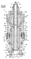
- the head 11 includes an internal body, consisting of a tubular part 12 with a threaded end to which a threaded ring 14 is screwed.
- the ring 14 is set on the ledge of a first end of a fixed support 16, consisting of a bush from which a radial appendix protrudes for connection to a rolling machine (not shown).
- the tubular part 12 also supports two bearings 18.
- the bearings 18 are distanced by a spacer and are set the one on the ledge of a second end of the fixed support 16 and the other set on the ledge of a ring 20.
- the bearings 18 support an external body consisting of a second tubular part. This has a first portion 22a, where the bearings 18 are connected and a second portion or sleeve 22b which protrudes in relation to the tubular part 12.
- the sleeve 22b has a flange 24 at its free end to which an entrance ring 26 is fixed by spacers.
- the sleeve 22b has eight longitudinal grooves 28 into each of which a rod 30 is inserted.
- Each rod 30 has an end connected to the sleeve 22b by an articulated connection 32.
- the rollers 36 are housed in an area between the flange 24 and the entrance ring 26.
- a pusher 38 is placed between the rollers 36.
- the pusher 38 has a portion which is integral with a cup plate 40, with its edge turned towards the sleeve 22b.
- the end of a rod is fixed to the plate 40 opposite to that where the pusher 38 is connected.
- This rod is made up of two portions, the first portion 42a is wider and is fixed to the plate 40, a second portion 42b, instead, is inserted inside the tubular part 12.
- a bush 44 is inserted on the first rod portion 42a, next to plate 40.
- a helical spring 46 is inserted on the bush 44 as elastic part. The spring 46 is locked between the plate 40 and the ring 20.
- the other end of the first portion 42a of the rod is in sliding contact with a raised edge 48 internally protruding from one end of the tubular part 12. In this way, it is the first portion 42a, and never the second portion 42b, which is always in contact with the raised edge 48 for any rod position.
- the end of the portion 42b of the rod is threaded and a nut is fixed to it which locks a striker plate 52 able to set against the ledge end of the tubular part 12.
- a pulley 54 is fixed on the portion 22a of the second tubular part, serving as a drive component on which a drive belt is wound, not shown for purposes of simplicity.
- the pulley 54 has eight dead holes 56 in each of which an arm 58 is connected by a spherical knuckle. Each arm 58 bears a socket 60, which can be inserted into a groove 62 of a ring-shaped part or sleeve 64 of the rolling head 11, which constitutes a support part.
- the socket 60 has a slot which houses a helical spring 66 as elastic part.
- the spring 66 is locked, on the other side, in a slot of a second socket 68 which instead slides in a through hole 70 of the ring-shaped part 64.
- the socket 68 has a hollow rear portion, which encloses the rods 30, and inclined lateral walls, which join with the inclined walls of the grooves 28 .
- a pin 72 is fixed which constitutes a central fulcrum of a lever 74.
- the lever 74 has a hook shaped end 76, able to hook up a pin 78 which is integral with the socket 60.
- a presser component or U-bolt 80 is pivoted at the opposite end of the lever 74, which radially pushes against the rods 30.
- the socket 68 is set on the side of the pulley 54 while the lever 74 is set on the side of the pressure rollers 36.
- the ring-shaped part 64 has locking parts which lock it and prevent its translation along the rolling head 11.
- Such locking parts include two ratchet gears 82, pivoted at 84 each being inside a groove 86.
- the two grooves 86 are made in diametrically opposite positions to the ring-shaped part 64.
- the ends of the ratchet gears 82 are inserted inside notches 88 each being kept in position by a spring 90.
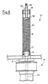
- the rolling head 11, according to the invention, can be also supplied with an external preloading adjustment device 92 of the pusher 38.
- a bush 94 locked by threaded dowels is placed at the end of the tubular part 12.
- the bush 94 has a squared portion where one end of a sleeve 96 is locked.
- the other end of the sleeve 96 is closed by a plate 98 with a threaded through hole.
- a threaded rod 100 bearing a piston 102 at its end.
- a spring 104 is locked between the piston 102 and the plate 52.
- a striker nut 106 is also screwed on rod 100, placed against plate 98 outside sleeve 96.
- the functioning of the rolling head with dynamic balancing is basically as follows.
- the pulley 54, and the second tubular part 22a, 22b integral with it, is previously rotated; thus the bottle neck (complete with cap) is inserted inside the second tubular part 22a, 22b.
- the bottle neck bears the cap beat against the pusher 38 and, overcoming the elastic reaction of the springs 66 and spring 46, moves the pressure rollers 36 radially and the pusher 38 axially, inserting itself inside the sleeve 22b of the second tubular part.
- the rotation of the second tubular part 22a, 22b causes the rotation of rods 30 and, therefore of rollers 36.
- rollers 36 press down the cap making it adhere to the bottle neck and cork, also at the undercuts.
- the centrifugal force tends to move the rods 30 radially outwards.
- the springs 66 are compressed and the sockets 60 are, in turn, pushed radially outwards.
- the levers 74 therefore turn around the respective pins 72 and radially push the U-bolts 80 on rods 30, to balance the head 11 again; in practice, the sockets 60 show a swing motion around the spherical knuckles inserted in the guide holes 56.
- the rolling head 11 is only dynamically balanced at a precise position of the ring-shaped part 64 (preloading on the pressure rollers 36 independent of the rotation speed).
- the rolling head 11 is self-closing, i.e. the load on rollers 36 increases with an increase in the rotation speed of pulley 54.
- the roller head 11 is self-opening, i.e. the load on rollers 36 decreases with an increase in the rotation speed of pulley 54.
- the lever 74 with hook 76, allows the quick release from socket 60. This allows the easy assembly and maintenance of the rolling head 11, in general, and especially of springs 66 and, at the same time, allows the notable radial reduction of the roller head 11 bulk.
- the preloading of the pusher 38 can be adjusted, to adapt it to particular working requirements, by using the device 92 in figure 4, when this is present.
- adjustment proves particularly simple, quick and very accurate. In order to do this, simply screw or unscrew the rod 100 from the plate 98 so as to axially move the rod 100 in relation to the sleeve 96. Since the spring 104 is locked between the piston 102 and the plate 52, this operation alters the preloading on the pusher 38.
Landscapes
- Engineering & Computer Science (AREA)
- Mechanical Engineering (AREA)
- Rolls And Other Rotary Bodies (AREA)
- Coating With Molten Metal (AREA)
- Spinning Or Twisting Of Yarns (AREA)
- Sealing Of Jars (AREA)
- Support Of The Bearing (AREA)
- Manipulator (AREA)
- Buildings Adapted To Withstand Abnormal External Influences (AREA)
- Supporting Of Heads In Record-Carrier Devices (AREA)
Claims (12)
- Tête de sertissage (11) à équilibrage dynamique, comportant un corps intérieur (12, 16) qui supporte un corps extérieur (22a, 22b), au moins une tige (30) étant montée articulée(s) sur ledit corps extérieur qui porte un galet presseur (36), ledit corps extérieur (22a, 22b) comportant également au moins un organe d'entraínement (54) pour son fonctionnement en rotation, ledit corps extérieur (22a, 22b) porte au moins un élément de support (64), d'un seul tenant à rotation avec lui, auquel, pour chaque tige, est fixé un levier (74) autour d'un point d'appui, caractérisé en ce que ledit levier (74) a une extrémité montée articulée sur un élément presseur (80), qui travaille contre ladite tige (30) et une extrémité opposée montée articulée sur une embase (60) qui pousse un élément élastique (66) contre ladite tige (30), ladite embase (60) étant montée articulée sur ladite tête de sertissage (11) par un bras (58) monté articulé sur ledit corps extérieur (22a, 22b), de sorte qu'elle peut s'approcher ou s'éloigner du corps extérieur (22a, 22b).
- Tête de sertissage (11) selon la revendication 1, caractérisée en ce que ledit élément(s) de support (64) comporte au moins un élément annulaire inséré sur ledit corps extérieur (22a, 22b).
- Tête de sertissage (11) selon la revendication 2, caractérisée en ce que ledit élément annulaire (64) coulisse axialement sur ledit corps extérieur (22a, 22b) et comporte des éléments de blocage (82, 84).
- Tête de sertissage (11) selon la revendication 2, caractérisée en ce que ledit élément annulaire (64) comporte des rainures (62) dans lesquelles sont insérées lesdites embases (60).
- Tête de sertissage (11) selon la revendication 2, caractérisée en ce que ledit élément annulaire (64) comporte des trous (70) par lesquels passent lesdits éléments élastiques (66) pour se mettre contre ladite tige (30).
- Tête de sertissage (11) selon la revendication 5, caractérisée en ce que dans lesdits trous (70) et aux extrémités desdits éléments élastiques (66) sont placées des deuxièmes embases (68) qui enferment ladite tige (30).
- Tête de sertissage (11) selon la revendication 1, caractérisée en ce que lesdits leviers (74) comportent un élément presseur (80), au moins à une extrémité de ladite tige (30), qui enferme ladite tige (30).
- Tête de sertissage (11) selon la revendication 1, caractérisée en ce que ladite extrémité dudit levier (74) montée articulée sur ladite embase (60) est en forme de crochet (76) et est en prise avec un axe (78) de ladite embase (60), afin de constituer un dispositif à déblocage rapide.
- Tête de sertissage (11) selon la revendication 1, caractérisée en ce que ledit corps extérieur (22a, 22b) comporte des rainures longitudinales (28) contenant lesdites tiges (30).
- Tête de sertissage (11) selon la revendication 9, caractérisée en ce que lesdites rainures longitudinales (28) ont des parois inclinées afin de rejoindre les parois inclinées d'une deuxième embase (68) reliée auxdites tiges (30).
- Tête de sertissage (11) selon la revendication 3, caractérisée en ce que lesdits éléments de blocage (82, 84) comportent des rochets (82) montés pivotants (en 84) sur ledit élément annulaire (64) et ayant des extrémités qui s'insèrent dans des encoches (88) dudit corps extérieur (22a, 22b).
- Tête de sertissage (11) selon la revendication 1, caractérisée en ce que ladite embase (60) est placée sur le côté de ladite poulie (54) tandis que le levier (74) est placé sur le côté desdits galets presseurs (36).
Applications Claiming Priority (2)
| Application Number | Priority Date | Filing Date | Title |
|---|---|---|---|
| IT1999MI002443A IT1314083B1 (it) | 1999-11-23 | 1999-11-23 | Testa rullatrice a bilanciamento dinamico. |
| ITMI992443 | 1999-11-23 |
Publications (2)
| Publication Number | Publication Date |
|---|---|
| EP1103514A1 EP1103514A1 (fr) | 2001-05-30 |
| EP1103514B1 true EP1103514B1 (fr) | 2003-09-24 |
Family
ID=11384002
Family Applications (1)
| Application Number | Title | Priority Date | Filing Date |
|---|---|---|---|
| EP00204089A Expired - Lifetime EP1103514B1 (fr) | 1999-11-23 | 2000-11-20 | Tête de sertissage avec équilibrage dynamique |
Country Status (4)
| Country | Link |
|---|---|
| EP (1) | EP1103514B1 (fr) |
| AT (1) | ATE250553T1 (fr) |
| DE (1) | DE60005461T2 (fr) |
| IT (1) | IT1314083B1 (fr) |
Families Citing this family (1)
| Publication number | Priority date | Publication date | Assignee | Title |
|---|---|---|---|---|
| ITTO20070791A1 (it) * | 2007-11-07 | 2009-05-08 | Robino & Galandrino Spa | Testa rullante per serrare capsule sigillanti di materiale deformabile su colli di bottiglie di vino, vino spumante, liquore, e simili. |
Family Cites Families (2)
| Publication number | Priority date | Publication date | Assignee | Title |
|---|---|---|---|---|
| IT1266159B1 (it) * | 1994-07-08 | 1996-12-23 | Robino E Calandrino S P A | Testa rullatrice per l'applicazione di capsule di sigillo su bottiglie in genere. |
| ES2128918B1 (es) * | 1996-01-24 | 2000-01-16 | Rivercap S A | Cabezal capsulador. |
-
1999
- 1999-11-23 IT IT1999MI002443A patent/IT1314083B1/it active
-
2000
- 2000-11-20 DE DE60005461T patent/DE60005461T2/de not_active Expired - Lifetime
- 2000-11-20 EP EP00204089A patent/EP1103514B1/fr not_active Expired - Lifetime
- 2000-11-20 AT AT00204089T patent/ATE250553T1/de not_active IP Right Cessation
Also Published As
| Publication number | Publication date |
|---|---|
| ITMI992443A1 (it) | 2001-05-23 |
| IT1314083B1 (it) | 2002-12-04 |
| DE60005461T2 (de) | 2004-06-24 |
| ITMI992443A0 (it) | 1999-11-23 |
| ATE250553T1 (de) | 2003-10-15 |
| DE60005461D1 (de) | 2003-10-30 |
| EP1103514A1 (fr) | 2001-05-30 |
Similar Documents
| Publication | Publication Date | Title |
|---|---|---|
| CA2152701C (fr) | Machine d'assemblage automatique pour flacon pulverisateur | |
| US5467527A (en) | Capping unit for automatically assembling pump-operated spray cap | |
| CN101772466B (zh) | 封盖机 | |
| CN110589732B (zh) | 用于借助容器封盖封闭容器的封盖头 | |
| CN101157432B (zh) | 用于安装预螺纹盖的拧入滚压头 | |
| US7661245B2 (en) | Capping device with bearing mechanism having a plurality of bearing members between a drive member and a capper body | |
| FR2593798A1 (fr) | Appareil reglable pour capsuler des recipients | |
| EP2177472B1 (fr) | Tête pour l'application de capsules filetées sur des conteneurs | |
| US5884450A (en) | Device for rapidly mounting/releasing units for fitting caps or lids to containers, in particular for mandrels of automatic machines | |
| US7836664B2 (en) | Unit for fitting screw caps to the necks of respective containers | |
| US5062917A (en) | Support element for the followers of a cam drive of a drive mechanism and a labelling station equipped with a support element | |
| US4086747A (en) | Headset device for a capping machine | |
| US3878667A (en) | Closure cap applying apparatus | |
| US5062918A (en) | Glue segments which can be attachable to a drive shaft of a labelling machine | |
| EP1273551B1 (fr) | Machine à capsuler avec une tête à capsuler | |
| US4089153A (en) | Capping machine | |
| EP1103514A1 (fr) | Tête de sertissage avec d'équilibrage dynamique | |
| EP0691302B1 (fr) | Tête de sertissage pour appliquer des capsules sur des bouteilles en général | |
| US3470667A (en) | Capping conversion apparatus and method | |
| WO2022071873A1 (fr) | Dispositif de vissage et de dévissage à autopréhension | |
| AU2005338145B2 (en) | Screwing/rolling head for pre-threaded caps | |
| ITPD20090004A1 (it) | Testa di tappatura per l'applicazione di tappi su contenitori | |
| DE60202113T2 (de) | Verschliessmaschine | |
| RU2206493C1 (ru) | Патрон для завальцовки металлического колпачка, в том числе колпачка типа "винт", на горловине сосуда | |
| US20250145439A1 (en) | Capping head for a capping machine, capping method and cap |
Legal Events
| Date | Code | Title | Description |
|---|---|---|---|
| PUAI | Public reference made under article 153(3) epc to a published international application that has entered the european phase |
Free format text: ORIGINAL CODE: 0009012 |
|
| AK | Designated contracting states |
Kind code of ref document: A1 Designated state(s): AT BE CH CY DE DK ES FI FR GB GR IE IT LI LU MC NL PT SE TR |
|
| AX | Request for extension of the european patent |
Free format text: AL;LT;LV;MK;RO;SI |
|
| 17P | Request for examination filed |
Effective date: 20010525 |
|
| AKX | Designation fees paid |
Free format text: AT BE CH CY DE DK ES FI FR GB GR IE IT LI LU MC NL PT SE TR |
|
| 17Q | First examination report despatched |
Effective date: 20020619 |
|
| GRAH | Despatch of communication of intention to grant a patent |
Free format text: ORIGINAL CODE: EPIDOS IGRA |
|
| GRAH | Despatch of communication of intention to grant a patent |
Free format text: ORIGINAL CODE: EPIDOS IGRA |
|
| GRAA | (expected) grant |
Free format text: ORIGINAL CODE: 0009210 |
|
| AK | Designated contracting states |
Kind code of ref document: B1 Designated state(s): AT BE CH CY DE DK ES FI FR GB GR IE IT LI LU MC NL PT SE TR |
|
| PG25 | Lapsed in a contracting state [announced via postgrant information from national office to epo] |
Ref country code: AT Free format text: LAPSE BECAUSE OF FAILURE TO SUBMIT A TRANSLATION OF THE DESCRIPTION OR TO PAY THE FEE WITHIN THE PRESCRIBED TIME-LIMIT Effective date: 20030924 Ref country code: FI Free format text: LAPSE BECAUSE OF FAILURE TO SUBMIT A TRANSLATION OF THE DESCRIPTION OR TO PAY THE FEE WITHIN THE PRESCRIBED TIME-LIMIT Effective date: 20030924 Ref country code: NL Free format text: LAPSE BECAUSE OF FAILURE TO SUBMIT A TRANSLATION OF THE DESCRIPTION OR TO PAY THE FEE WITHIN THE PRESCRIBED TIME-LIMIT Effective date: 20030924 Ref country code: TR Free format text: LAPSE BECAUSE OF FAILURE TO SUBMIT A TRANSLATION OF THE DESCRIPTION OR TO PAY THE FEE WITHIN THE PRESCRIBED TIME-LIMIT Effective date: 20030924 Ref country code: CH Free format text: LAPSE BECAUSE OF FAILURE TO SUBMIT A TRANSLATION OF THE DESCRIPTION OR TO PAY THE FEE WITHIN THE PRESCRIBED TIME-LIMIT Effective date: 20030924 Ref country code: LI Free format text: LAPSE BECAUSE OF FAILURE TO SUBMIT A TRANSLATION OF THE DESCRIPTION OR TO PAY THE FEE WITHIN THE PRESCRIBED TIME-LIMIT Effective date: 20030924 Ref country code: BE Free format text: LAPSE BECAUSE OF FAILURE TO SUBMIT A TRANSLATION OF THE DESCRIPTION OR TO PAY THE FEE WITHIN THE PRESCRIBED TIME-LIMIT Effective date: 20030924 |
|
| REG | Reference to a national code |
Ref country code: GB Ref legal event code: FG4D |
|
| REG | Reference to a national code |
Ref country code: CH Ref legal event code: EP |
|
| REG | Reference to a national code |
Ref country code: IE Ref legal event code: FG4D |
|
| REF | Corresponds to: |
Ref document number: 60005461 Country of ref document: DE Date of ref document: 20031030 Kind code of ref document: P |
|
| PG25 | Lapsed in a contracting state [announced via postgrant information from national office to epo] |
Ref country code: CY Free format text: LAPSE BECAUSE OF FAILURE TO SUBMIT A TRANSLATION OF THE DESCRIPTION OR TO PAY THE FEE WITHIN THE PRESCRIBED TIME-LIMIT Effective date: 20031120 Ref country code: IE Free format text: LAPSE BECAUSE OF NON-PAYMENT OF DUE FEES Effective date: 20031120 Ref country code: LU Free format text: LAPSE BECAUSE OF NON-PAYMENT OF DUE FEES Effective date: 20031120 |
|
| PG25 | Lapsed in a contracting state [announced via postgrant information from national office to epo] |
Ref country code: MC Free format text: LAPSE BECAUSE OF NON-PAYMENT OF DUE FEES Effective date: 20031130 |
|
| PG25 | Lapsed in a contracting state [announced via postgrant information from national office to epo] |
Ref country code: GR Free format text: LAPSE BECAUSE OF FAILURE TO SUBMIT A TRANSLATION OF THE DESCRIPTION OR TO PAY THE FEE WITHIN THE PRESCRIBED TIME-LIMIT Effective date: 20031224 Ref country code: DK Free format text: LAPSE BECAUSE OF FAILURE TO SUBMIT A TRANSLATION OF THE DESCRIPTION OR TO PAY THE FEE WITHIN THE PRESCRIBED TIME-LIMIT Effective date: 20031224 Ref country code: SE Free format text: LAPSE BECAUSE OF FAILURE TO SUBMIT A TRANSLATION OF THE DESCRIPTION OR TO PAY THE FEE WITHIN THE PRESCRIBED TIME-LIMIT Effective date: 20031224 |
|
| PG25 | Lapsed in a contracting state [announced via postgrant information from national office to epo] |
Ref country code: ES Free format text: LAPSE BECAUSE OF FAILURE TO SUBMIT A TRANSLATION OF THE DESCRIPTION OR TO PAY THE FEE WITHIN THE PRESCRIBED TIME-LIMIT Effective date: 20040104 |
|
| NLV1 | Nl: lapsed or annulled due to failure to fulfill the requirements of art. 29p and 29m of the patents act | ||
| REG | Reference to a national code |
Ref country code: CH Ref legal event code: PL |
|
| ET | Fr: translation filed | ||
| PLBE | No opposition filed within time limit |
Free format text: ORIGINAL CODE: 0009261 |
|
| STAA | Information on the status of an ep patent application or granted ep patent |
Free format text: STATUS: NO OPPOSITION FILED WITHIN TIME LIMIT |
|
| REG | Reference to a national code |
Ref country code: IE Ref legal event code: MM4A |
|
| 26N | No opposition filed |
Effective date: 20040625 |
|
| PG25 | Lapsed in a contracting state [announced via postgrant information from national office to epo] |
Ref country code: GB Free format text: LAPSE BECAUSE OF NON-PAYMENT OF DUE FEES Effective date: 20041120 |
|
| GBPC | Gb: european patent ceased through non-payment of renewal fee |
Effective date: 20041120 |
|
| PG25 | Lapsed in a contracting state [announced via postgrant information from national office to epo] |
Ref country code: PT Free format text: LAPSE BECAUSE OF NON-PAYMENT OF DUE FEES Effective date: 20040224 |
|
| PGFP | Annual fee paid to national office [announced via postgrant information from national office to epo] |
Ref country code: FR Payment date: 20101130 Year of fee payment: 11 |
|
| PGFP | Annual fee paid to national office [announced via postgrant information from national office to epo] |
Ref country code: DE Payment date: 20101119 Year of fee payment: 11 |
|
| PGFP | Annual fee paid to national office [announced via postgrant information from national office to epo] |
Ref country code: IT Payment date: 20101124 Year of fee payment: 11 |
|
| REG | Reference to a national code |
Ref country code: FR Ref legal event code: ST Effective date: 20120731 |
|
| PG25 | Lapsed in a contracting state [announced via postgrant information from national office to epo] |
Ref country code: IT Free format text: LAPSE BECAUSE OF NON-PAYMENT OF DUE FEES Effective date: 20111120 |
|
| REG | Reference to a national code |
Ref country code: DE Ref legal event code: R119 Ref document number: 60005461 Country of ref document: DE Effective date: 20120601 |
|
| PG25 | Lapsed in a contracting state [announced via postgrant information from national office to epo] |
Ref country code: FR Free format text: LAPSE BECAUSE OF NON-PAYMENT OF DUE FEES Effective date: 20111130 |
|
| PG25 | Lapsed in a contracting state [announced via postgrant information from national office to epo] |
Ref country code: DE Free format text: LAPSE BECAUSE OF NON-PAYMENT OF DUE FEES Effective date: 20120601 |