EP1103647A2 - Filtereinrichtung für einen Wäschetrockner - Google Patents
Filtereinrichtung für einen Wäschetrockner Download PDFInfo
- Publication number
- EP1103647A2 EP1103647A2 EP00125570A EP00125570A EP1103647A2 EP 1103647 A2 EP1103647 A2 EP 1103647A2 EP 00125570 A EP00125570 A EP 00125570A EP 00125570 A EP00125570 A EP 00125570A EP 1103647 A2 EP1103647 A2 EP 1103647A2
- Authority
- EP
- European Patent Office
- Prior art keywords
- filter
- filter device
- filter body
- dryer according
- clothes dryer
- Prior art date
- Legal status (The legal status is an assumption and is not a legal conclusion. Google has not performed a legal analysis and makes no representation as to the accuracy of the status listed.)
- Granted
Links
- 238000001914 filtration Methods 0.000 title description 2
- 238000007789 sealing Methods 0.000 claims abstract description 15
- 238000000034 method Methods 0.000 claims description 24
- 238000012423 maintenance Methods 0.000 claims description 6
- 238000011144 upstream manufacturing Methods 0.000 claims description 3
- 238000004140 cleaning Methods 0.000 description 7
- 238000013461 design Methods 0.000 description 5
- 239000000428 dust Substances 0.000 description 4
- 239000002245 particle Substances 0.000 description 3
- 238000010438 heat treatment Methods 0.000 description 2
- 238000012549 training Methods 0.000 description 2
- 238000009825 accumulation Methods 0.000 description 1
- 230000015572 biosynthetic process Effects 0.000 description 1
- 238000011161 development Methods 0.000 description 1
- 230000018109 developmental process Effects 0.000 description 1
- 238000001035 drying Methods 0.000 description 1
- 238000009434 installation Methods 0.000 description 1
- 238000005406 washing Methods 0.000 description 1
Images


Classifications
-
- D—TEXTILES; PAPER
- D06—TREATMENT OF TEXTILES OR THE LIKE; LAUNDERING; FLEXIBLE MATERIALS NOT OTHERWISE PROVIDED FOR
- D06F—LAUNDERING, DRYING, IRONING, PRESSING OR FOLDING TEXTILE ARTICLES
- D06F58/00—Domestic laundry dryers
- D06F58/20—General details of domestic laundry dryers
- D06F58/22—Lint collecting arrangements
Definitions
- the invention relates to a filter device for a tumble dryer with a cup-shaped trained filter body with an outer filter surface and an inner arranged therein Filter surface and an upstream side sealing the outer filter surface to the filter housing arranged sealing edge for an air flow directed into the interior of the pot.
- Such a filter device is for a handheld vacuum cleaner from DE 196 53 570 A1 known.
- the filter device is pot-shaped and on the air inlet side Sealed housing so that the air flow is directed into the interior of the filter body.
- the dust particles settle on the inside of the filter surface.
- the cup-shaped filter body has an outer filter surface in the manner of an open bag by a support structure is held.
- the closed lower end of the bag is arched into the inside of the pot arranged and thus forms the inner filter surface arranged inside the filter body. This increases the effective filter area.
- the support structure for the filter bag is designed to be resilient and expands under the influence of the suction air flow. at If the air flow ceases to exist, the supporting frame returns to its original shape. Through this Training, the dust particles deposited on the filter surface are shaken off and in Dust room collected.
- This filter device is for manual cleaning of the filter surface not suitable for the filter bag due to the spring-elastic support structure.
- a filter device for a clothes dryer in which a cup-shaped filter insert is inserted into a receiving body and in Intake air flow for the dry air is arranged.
- the intake air for the dry air flow passed through a filter device to this air for a hygienic drying process rid of dust particles and the like.
- the receiving body is cylindrical and has on its periphery suction openings for one directed into the filter interior Air flow on.
- the filter insert can be removed from the holder body for cleaning become.
- Such an intake air filter is for filtering out the lint from the process air flow not suitable.
- the invention thus addresses the problem of a filter device suitable for manual cleaning for a tumble dryer with a large effective filter area for an optimal To design lint removal from the process air flow.
- the filter device with a dimensionally stable support structure for an outer and one arranged therein inner filter body is formed.
- the filter elements are arranged one inside the other Air flow through the special design of the support structure in parallel and not in succession flows through.
- This configuration makes the effective filter area with a small installation space the filter device enlarged.
- the filter bodies are together in the area of their bottom surfaces connected and removed together for cleaning. Behind the filter device the impeller is arranged, which is easy after removing the filter device is accessible and can also be cleaned.
- a particular advantage is the divisible Design of the filter device.
- the inner and outer filter bodies are made up together removed from the device and can be separated for cleaning. This is in the area of Bottom surfaces of the two filter bodies have a connection arrangement which connects the two filter bodies interlocked, provided.
- FIG. 1 shows the arrangement of the filter device (1) according to the invention in shown a dryer.
- the tumble dryer is rotatable in a housing (2) stored laundry drum (3), the loading opening (4) of the laundry drum (3) closing door (5), a blower (6) for generating a process air flow through the Washing drum (3) and a heating device (7).
- the process air flow is via a Process air duct section (8) with the heating device (7) to the drum inlet (9) through which Laundry drum (3) and via a process air duct section (10) from the drum outlet (11) led to the blower (6).
- the lint filter device (1) is the drum outlet (11) Process air downstream and preferably in the lower part of the process air duct section (10), which is designed as a filter housing (12).
- the control of the process air flow through the clothes dryer is shown with arrows.
- the lint filter device (1) is accessible from the front of the housing (2) and is accessible from the outside via a filter opening (13) inserted into the process air duct section (10).
- the filter device (1) is this first embodiment behind a filter opening (13) in the process air duct section (10) tightly closing maintenance flap (14) in the front of the housing (2) and has a handle (15).
- the design of this filter device (1) is shown in FIG. 2.
- FIG 2 shows the filter device (1) to be arranged behind a maintenance flap (14) as Detail.
- the filter device (1) consists of two columnar filter bodies (16, 17).
- the filter bodies (16, 17) each consist of a dimensionally stable columnar Support structure that support the filter surfaces (18).
- the inner filter body (17) is inside the outer filter body (16) arranged.
- the filter bodies (16, 17) are in the area of their bottom surfaces connected with each other.
- the filter body (16, 17) can be unsolvable or via a releasable connection to be connected.
- the supporting structures of the two filter bodies (16, 17) form a seen in the air flow direction in the embodiment shown annular closed bottom surface (19).
- the webs (20) end on the upper molded part on the upstream side Edge (21).
- This edge (21) is a sealing edge to the filter housing (12) for the filter device (1, see also Figure 1).
- the air flow becomes due to the formation of the sealing edge passed into the pot interior of the filter device (1).
- From the inner ring the ring-shaped trained bottom surface (19) extends the inner filter body (17).
- the In the embodiment shown, webs (22) end on the bottom surface (19) opposite side in a cover surface (23).
- the top surface can be closed be trained.
- the handle (15) is arranged, over which the entire Filter device (1) unlocked and can be removed.
- the top surface (23) can also be used a further screen surface (not shown).
- the inner filter body (17) is at the illustrated embodiment compared to the outer filter body (16) in the area the top surface (23) is elongated in the axial direction.
- the top surface (23) is in the installed state in this variant behind the filter opening (13) in the process air duct (10) sealing final maintenance flap (14).
- the inner and outer filter body (16, 17) are preferably releasably connected to one another so that the filter surfaces (18) are light are to be cleaned by hand.
- the bottom surface is with a handle (24) trained.
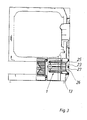
- FIG 3 shows the filter device according to another embodiment with an integrated Filter cover (25), which seals the filter opening (13).
- the filter cover (25) is in the essentially flush in the front of the housing (2) and is with a recessed grip (26), in which is arranged a handle (27). With the handle (27) the entire filter device (1) can be removed from the filter opening (13). Training this Filter device (1) is shown in Figure 4.
- In this version of the filter device (1) carries the top surface (23) of the inner filter body (17) for the integrated filter cover (25) the sealing end of the process air duct (10).
- the filter cover (25) is one of the Filter opening (13) adapted circumferential seal (not shown).
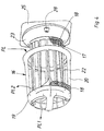
- Figure 4 shows the structure of the filter device according to Figure 3 as a detail.
- the structure differs essentially only in the design of the top surface (23).
- the ring-shaped bottom surface is also with a handle for better handling when separating formed by the inner and outer filter body (16, 17).
- the filter cover (25) has one Locking device (28) for the filter device (1) in the filter opening (13).
- the process air flow through the filter body (16, 17) of the filter device is shown in FIG (1).
- the process air flow occurs in the area of the axially extended area of the inner filter body (17) radially into the filter device (1).
- the air flow is divided into partial air flows in the filter body, in which a part of the process air via the inner filter body (17) in the direction of PL1 and Part is guided over the outer filter body (16) in the direction of PL2.
- the fluff builds up the outside of the inner filter body (17) and on the inside of the outer filter body (16).
- the filter device (1) is removed from the filter opening as a unit for cleaning purposes (13) taken.
- the lint accumulation is located inside the drip of the filter device (1).
- the two filter bodies (16, 17) Cut.
- the lint can well from the outer surface of the inner filter body (17) and Inner surface of the outer filter body (16) can be eliminated.
- the air flow in the filter device (1) according to FIG. 4 is as described for FIG. 2.
- a major difference here is in the top surface (23), with an integrated filter cover (25), which seals the filter opening (13) in the process air duct (10). So that's not it Handle shown for the filter device (1) not in the process air flow.
- the handle for the filter device is arranged on the top surface (23) (1) in the process air flow behind the maintenance flap (14).
- the filter bodies (16, 17) are columnar in the exemplary embodiment shown.
- the columns can have different cross-sectional shapes.
- the preferred The cross-sectional shape is approximately elliptical for the outer filter body (16) and for the inner one Filter body (16) circular.
- Another embodiment is the combination of outer filter body (16) with a circular cross section and inner filter body (17) with elliptical cross section possible.
- Both filter bodies (16, 17) can also be circular or elliptical cross sections.
Landscapes
- Engineering & Computer Science (AREA)
- Textile Engineering (AREA)
- Detail Structures Of Washing Machines And Dryers (AREA)
- Filtering Of Dispersed Particles In Gases (AREA)
- Drying Of Solid Materials (AREA)
Abstract
Description
- Figur 1
- Einen Wäschetrockner mit einer erfindungsgemäß ausgebildeten Filtereinrichtung, die hinter einer Wartungsklappe angeordnet ist,
- Figur 2
- die Filtereinrichtung als Einzelheit gemäß Figur 1,
- Figur 3
- ein weiteres Ausführungsbeispiel für einen Wäschetrockner mit einer erfindungsgemäß ausgebildeten Filtereinrichtung mit integriertem Filterdeckel,
- Figur 4
- die Filtereinrichtung als Einzelheit gemäß Figur 3.
Claims (12)
- Filtereinrichtung für einen Wäschetrockner mit einem topfförmig ausgebildeten von einer Tragstruktur gehaltenen Filterkörper mit einer äußeren Filterfläche und einer darin angeordneten inneren Filterfläche und einem die äußere Filterfläche zum Filtergehäuse abdichtenden anströmseitig angeordneten Dichtrand für eine in das Topfinnere gerichtete Luftströmung,
dadurch gekennzeichnet,
dass die äußere und die innere Filterfläche (18) jeweils von einer säulenförmig ausgebildeten formstabilen Tragstruktur gehalten werden und mit dieser einen äußeren sowie einen inneren Filterkörper (16, 17) bilden, die im Bereich ihrer Bodenflächen miteinander verbunden sind. - Filtereinrichtung für einen Wäschetrockner nach Anspruch 1,
dadurch gekennzeichnet,
dass der innere Filterkörper (17) unlösbar mit dem äußeren Filterkörper (16) verbunden ist. - Filtereinrichtung für einen Wäschetrockner nach Anspruch 1,
dadurch gekennzeichnet,
dass der innere Filterkörper (17) lösbar mit dem äußeren Filterkörper (16) verbunden ist. - Filtereinrichtung für einen Wäschetrockner nach Anspruch 2 oder 3,
dadurch gekennzeichnet,
dass die Tragstruktur des äußeren Filterkörpers (16) mit der Tragstruktur des inneren Filterkörpers (17) im Bodenbereich eine ringförmige Bodenfläche (19) bildet. - Filtereinrichtung für einen Wäschetrockner nach Anspruch 4,
dadurch gekennzeichnet,
dass die Tragstruktur des äußeren Filterkörpers vom äußeren Umfang der ringförmigen Bodenfläche (19) ausgehende, in axialer Richtung erstreckende, Stege (20) aufweist, welche die Filterfläche (18) tragen und wobei die Stege (20) an einem oberen anströmseitig angeformten Rand (21) enden, welcher als Dichtrand zum Filtergehäuse (12) für die Filtereinrichtung ausgebildet ist. - Filtereinrichtung für einen Wäschetrockner nach Anspruch 4,
dadurch gekennzeichnet,
dass die Tragstruktur des inneren Filterkörpers vom inneren Umfang der ringförmigen Bodenfläche (19) ausgehende, in axialer Richtung erstreckende, Stege (22) aufweist, welche die Filterfläche (18) tragen und wobei die Stege (22) auf der der Bodenfläche (19) gegenüberliegenden Seite in einer Deckfläche (23) enden. - Filtereinrichtung für einen Wäschetrockner nach mindestens einem der Ansprüche 1 bis 6,
dadurch gekennzeichnet,
dass der äußere Filterkörper (16) mit dem dichtend abschließenden Rand (21) die Filtereinrichtung (1) zum Filtergehäuse (10') abdichtet und der innere Filterkörper (17) mit einem an der Deckfläche (23) angeordneten Filterdeckel (25) einen dichtenden Abschluss der Filteröffnung (13) im Prozessluftkanal (10) über eine am Filterdeckel (25) angeordnete Dichtung bewirkt. - Filtereinrichtung für einen Wäschetrockner nach mindestens einem der Ansprüche 1 bis 6,
dadurch gekennzeichnet,
dass der äußere Filterkörper (16) mit einem dichtend abschließenden Rand (21) die Filtereinrichtung (1) zum Filtergehäuse (10') abdichtet und die Deckfläche (23) des inneren Filterkörpers (17) hinter einer die Filteröffnung (13) dicht verschließenden Wartungsklappe (14) im Prozessluftstrom liegt. - Filtereinrichtung für einen Wäschetrockner nach mindestens einem der Ansprüche 1 bis 8,
dadurch gekennzeichnet,
dass die Querschnittsform der säulenförmig ausgebildeten Filterkörper (16 oder 17) annähernd elliptisch ist und/oder kreisförmig ist. - Filtereinrichtung für einen Wäschetrockner nach mindestens einem der Ansprüche 1 bis 9,
dadurch gekennzeichnet,
dass der innere Filterkörper (17) gegenüber dem äußeren Filterkörper (16) im Bereich der Deckfläche (23) in axialer Richtung verlängert ausgebildet ist. - Filtereinrichtung für einen Wäschetrockner nach Anspruch 8,
dadurch gekennzeichnet,
dass der Prozessluftstrom PL im Bereich der axialen Verlängerung radial in das Innere der Filtereinrichtung (1) eintritt als Teil-Prozessluftstrom PL1 axial aus dem inneren Filterkörper (17) und als Teil-Prozessluftstrom PL2 radial aus dem äußeren Filterkörper (16) austritt. - Filtereinrichtung für einen Wäschetrockner nach mindestens einem der Ansprüche 1 bis 11,
dadurch gekennzeichnet,
dass die Filtereinrichtung (1) über eine Verriegelungseinrichtung (28) in der Filteröffnung (13) fixiert ist.
Applications Claiming Priority (2)
| Application Number | Priority Date | Filing Date | Title |
|---|---|---|---|
| DE19956897 | 1999-11-26 | ||
| DE19956897 | 1999-11-26 |
Publications (3)
| Publication Number | Publication Date |
|---|---|
| EP1103647A2 true EP1103647A2 (de) | 2001-05-30 |
| EP1103647A3 EP1103647A3 (de) | 2002-06-26 |
| EP1103647B1 EP1103647B1 (de) | 2004-06-02 |
Family
ID=7930393
Family Applications (1)
| Application Number | Title | Priority Date | Filing Date |
|---|---|---|---|
| EP00125570A Expired - Lifetime EP1103647B1 (de) | 1999-11-26 | 2000-11-22 | Wäschetrockner mit einer Filtereinrichtung |
Country Status (3)
| Country | Link |
|---|---|
| EP (1) | EP1103647B1 (de) |
| AT (1) | ATE268404T1 (de) |
| DE (2) | DE10058285C2 (de) |
Cited By (2)
| Publication number | Priority date | Publication date | Assignee | Title |
|---|---|---|---|---|
| EP1655401A1 (de) * | 2004-11-05 | 2006-05-10 | LG Electronics, Inc. | Waschmaschine kombiniert mit einem Trockner |
| EP2403985A4 (de) * | 2009-03-03 | 2016-01-06 | Lg Electronics Inc | Wärmepumpenmodul und wäschebehandlungsvorrichtung damit |
Families Citing this family (3)
| Publication number | Priority date | Publication date | Assignee | Title |
|---|---|---|---|---|
| US9808770B2 (en) | 2013-05-14 | 2017-11-07 | Pall Corporation | High throughput membrane with channels |
| DE102015103884A1 (de) | 2015-03-17 | 2016-09-22 | Miele & Cie. Kg | Flusenfilter für einen Wäschetrockner, Wäschetrockner und Verfahren zum Betreiben eines Wäschetrockners |
| EP3467187B1 (de) | 2017-10-09 | 2021-12-22 | Whirlpool Corporation | Zur verwendung in einer maschine zum trocknen von wäsche konfigurierter filter und mit solch einem filter ausgestattete maschine zum trocknen von wäsche |
Family Cites Families (4)
| Publication number | Priority date | Publication date | Assignee | Title |
|---|---|---|---|---|
| US3568413A (en) * | 1969-07-23 | 1971-03-09 | Dustbane Enterprises Ltd | Suction cleaners |
| US5431706A (en) * | 1993-10-05 | 1995-07-11 | Dry Systems Technologies | Disposable particulate filter |
| US5681363A (en) * | 1996-03-18 | 1997-10-28 | Tucker; Deborah R. | Vacuum cleaner filter shaker |
| DE19644400A1 (de) * | 1996-10-25 | 1998-04-30 | Aeg Hausgeraete Gmbh | Elektrischer Abluft-Wäschetrockner |
-
2000
- 2000-11-22 EP EP00125570A patent/EP1103647B1/de not_active Expired - Lifetime
- 2000-11-22 DE DE10058285A patent/DE10058285C2/de not_active Expired - Fee Related
- 2000-11-22 AT AT00125570T patent/ATE268404T1/de not_active IP Right Cessation
- 2000-11-22 DE DE50006675T patent/DE50006675D1/de not_active Expired - Lifetime
Cited By (2)
| Publication number | Priority date | Publication date | Assignee | Title |
|---|---|---|---|---|
| EP1655401A1 (de) * | 2004-11-05 | 2006-05-10 | LG Electronics, Inc. | Waschmaschine kombiniert mit einem Trockner |
| EP2403985A4 (de) * | 2009-03-03 | 2016-01-06 | Lg Electronics Inc | Wärmepumpenmodul und wäschebehandlungsvorrichtung damit |
Also Published As
| Publication number | Publication date |
|---|---|
| ATE268404T1 (de) | 2004-06-15 |
| DE10058285A1 (de) | 2001-07-05 |
| DE10058285C2 (de) | 2003-04-30 |
| EP1103647B1 (de) | 2004-06-02 |
| EP1103647A3 (de) | 2002-06-26 |
| DE50006675D1 (de) | 2004-07-08 |
Similar Documents
| Publication | Publication Date | Title |
|---|---|---|
| DE10347454B4 (de) | Filteranordnung für eine Staubsammelvorrichtung vom Wirbelungstyp eines Staubsaugers | |
| DE10353321B4 (de) | Filtervorrichtung für eine Staubsammelvorrichtung vom Wirbelungstyp eines Staubsaugers | |
| DE69925157T2 (de) | Stielstaubsauger mit zyklonartiger luftströmung | |
| DE10356156B4 (de) | Wirbelungs-Staubsammelvorrichtung eines Staubsaugers | |
| DE202015008649U1 (de) | Staubsammler für Staubsauger | |
| DE202011000664U1 (de) | Staubsammelbehälter und Staubsauger mit demselben | |
| DE2802369A1 (de) | Filtervorrichtung zum filtern von durch staub und faserabfaelle verunreinigter luft | |
| DE112007001163T5 (de) | Einstufiger Zyklonstaubsauger | |
| DE10222656A1 (de) | Zyklon-Staubsammelvorrichtung für die Verwendung in Staubsaugern | |
| DE1951306A1 (de) | Elektrischer Staubsauger | |
| DE112012000251T5 (de) | Staubbehälter für Staubsauger | |
| DE2234738A1 (de) | Doppelfilterbeutel und verfahren | |
| DE102013108565B4 (de) | Staubsauger mit einem Filterelement | |
| DE3733653A1 (de) | Luftreiniger fuer brennkraftmaschinen | |
| DE102016118806A1 (de) | Staubsauger sowie System aus einem Staubsauger und einer Basisstation | |
| DE10058285C2 (de) | Filtereinrichtung für einen Wäschetrockner | |
| DE202010010313U1 (de) | Abfallfiltervorrichtung für Staubsauger | |
| DE19648561A1 (de) | Absaugeinrichtung an einer Textilmaschine | |
| EP3984430A1 (de) | Abscheidesystem mit einer vergrösserten filterfläche | |
| DE102017208966B4 (de) | Filteranordnung mit einem Flachfilter | |
| EP0848980B1 (de) | Vorrichtung zur Befestigung von Filterschläuchen eines Schlauch-filters an einem Rüttelrahmen | |
| EP3070200A1 (de) | Flusenfilter für einen wäschetrockner, wäschetrockner und verfahren zum betreiben eines wäschetrockners | |
| DE9212226U1 (de) | Wäschetrockner | |
| EP3764861B1 (de) | Sauggerät | |
| DE861175C (de) | Luftreiniger fuer die Ansaugluft von Brennkraftmaschinen, Druckluft-Erzeugungsanlagen u. dgl. fuer Vor- und Feinabscheidung mittels Zyklon und Nassluftfilter in konzentrischer Anordnung |
Legal Events
| Date | Code | Title | Description |
|---|---|---|---|
| PUAI | Public reference made under article 153(3) epc to a published international application that has entered the european phase |
Free format text: ORIGINAL CODE: 0009012 |
|
| AK | Designated contracting states |
Kind code of ref document: A2 Designated state(s): AT BE CH CY DE DK ES FI FR GB GR IE IT LI LU MC NL PT SE TR |
|
| AX | Request for extension of the european patent |
Free format text: AL;LT;LV;MK;RO;SI |
|
| PUAL | Search report despatched |
Free format text: ORIGINAL CODE: 0009013 |
|
| AK | Designated contracting states |
Kind code of ref document: A3 Designated state(s): AT BE CH CY DE DK ES FI FR GB GR IE IT LI LU MC NL PT SE TR |
|
| AX | Request for extension of the european patent |
Free format text: AL;LT;LV;MK;RO;SI |
|
| 17P | Request for examination filed |
Effective date: 20021130 |
|
| AKX | Designation fees paid |
Designated state(s): AT BE CH CY DE DK ES FI FR GB GR IE IT LI LU MC NL PT SE TR |
|
| 17Q | First examination report despatched |
Effective date: 20030328 |
|
| RAP1 | Party data changed (applicant data changed or rights of an application transferred) |
Owner name: MIELE & CIE. KG |
|
| RTI1 | Title (correction) |
Free format text: LAUNDRY DRYER WITH A FILTERING DEVICE |
|
| GRAP | Despatch of communication of intention to grant a patent |
Free format text: ORIGINAL CODE: EPIDOSNIGR1 |
|
| GRAS | Grant fee paid |
Free format text: ORIGINAL CODE: EPIDOSNIGR3 |
|
| GRAA | (expected) grant |
Free format text: ORIGINAL CODE: 0009210 |
|
| AK | Designated contracting states |
Kind code of ref document: B1 Designated state(s): AT BE CH CY DE DK ES FI FR GB GR IE IT LI LU MC NL PT SE TR |
|
| PG25 | Lapsed in a contracting state [announced via postgrant information from national office to epo] |
Ref country code: TR Free format text: LAPSE BECAUSE OF FAILURE TO SUBMIT A TRANSLATION OF THE DESCRIPTION OR TO PAY THE FEE WITHIN THE PRESCRIBED TIME-LIMIT Effective date: 20040602 Ref country code: IE Free format text: LAPSE BECAUSE OF FAILURE TO SUBMIT A TRANSLATION OF THE DESCRIPTION OR TO PAY THE FEE WITHIN THE PRESCRIBED TIME-LIMIT Effective date: 20040602 Ref country code: FI Free format text: LAPSE BECAUSE OF FAILURE TO SUBMIT A TRANSLATION OF THE DESCRIPTION OR TO PAY THE FEE WITHIN THE PRESCRIBED TIME-LIMIT Effective date: 20040602 Ref country code: CY Free format text: LAPSE BECAUSE OF FAILURE TO SUBMIT A TRANSLATION OF THE DESCRIPTION OR TO PAY THE FEE WITHIN THE PRESCRIBED TIME-LIMIT Effective date: 20040602 |
|
| REG | Reference to a national code |
Ref country code: GB Ref legal event code: FG4D Free format text: NOT ENGLISH |
|
| REG | Reference to a national code |
Ref country code: CH Ref legal event code: NV Representative=s name: PA ALDO ROEMPLER Ref country code: CH Ref legal event code: EP |
|
| REF | Corresponds to: |
Ref document number: 50006675 Country of ref document: DE Date of ref document: 20040708 Kind code of ref document: P |
|
| REG | Reference to a national code |
Ref country code: IE Ref legal event code: FG4D Free format text: GERMAN |
|
| PG25 | Lapsed in a contracting state [announced via postgrant information from national office to epo] |
Ref country code: SE Free format text: LAPSE BECAUSE OF FAILURE TO SUBMIT A TRANSLATION OF THE DESCRIPTION OR TO PAY THE FEE WITHIN THE PRESCRIBED TIME-LIMIT Effective date: 20040902 Ref country code: GR Free format text: LAPSE BECAUSE OF FAILURE TO SUBMIT A TRANSLATION OF THE DESCRIPTION OR TO PAY THE FEE WITHIN THE PRESCRIBED TIME-LIMIT Effective date: 20040902 Ref country code: DK Free format text: LAPSE BECAUSE OF FAILURE TO SUBMIT A TRANSLATION OF THE DESCRIPTION OR TO PAY THE FEE WITHIN THE PRESCRIBED TIME-LIMIT Effective date: 20040902 |
|
| PG25 | Lapsed in a contracting state [announced via postgrant information from national office to epo] |
Ref country code: ES Free format text: LAPSE BECAUSE OF FAILURE TO SUBMIT A TRANSLATION OF THE DESCRIPTION OR TO PAY THE FEE WITHIN THE PRESCRIBED TIME-LIMIT Effective date: 20040913 |
|
| GBT | Gb: translation of ep patent filed (gb section 77(6)(a)/1977) |
Effective date: 20040903 |
|
| PG25 | Lapsed in a contracting state [announced via postgrant information from national office to epo] |
Ref country code: LU Free format text: LAPSE BECAUSE OF NON-PAYMENT OF DUE FEES Effective date: 20041122 |
|
| PG25 | Lapsed in a contracting state [announced via postgrant information from national office to epo] |
Ref country code: MC Free format text: LAPSE BECAUSE OF NON-PAYMENT OF DUE FEES Effective date: 20041130 Ref country code: BE Free format text: LAPSE BECAUSE OF NON-PAYMENT OF DUE FEES Effective date: 20041130 |
|
| REG | Reference to a national code |
Ref country code: IE Ref legal event code: FD4D |
|
| ET | Fr: translation filed | ||
| PLBE | No opposition filed within time limit |
Free format text: ORIGINAL CODE: 0009261 |
|
| STAA | Information on the status of an ep patent application or granted ep patent |
Free format text: STATUS: NO OPPOSITION FILED WITHIN TIME LIMIT |
|
| 26N | No opposition filed |
Effective date: 20050303 |
|
| BERE | Be: lapsed |
Owner name: *MIELE & CIE. K.G. Effective date: 20041130 |
|
| REG | Reference to a national code |
Ref country code: GB Ref legal event code: 746 Effective date: 20061019 |
|
| BERE | Be: lapsed |
Owner name: *MIELE & CIE. K.G. Effective date: 20041130 |
|
| PG25 | Lapsed in a contracting state [announced via postgrant information from national office to epo] |
Ref country code: PT Free format text: LAPSE BECAUSE OF NON-PAYMENT OF DUE FEES Effective date: 20041102 |
|
| REG | Reference to a national code |
Ref country code: CH Ref legal event code: PCAR Free format text: ALDO ROEMPLER PATENTANWALT;BRENDENWEG 11 POSTFACH 154;9424 RHEINECK (CH) |
|
| PGFP | Annual fee paid to national office [announced via postgrant information from national office to epo] |
Ref country code: CH Payment date: 20081124 Year of fee payment: 9 Ref country code: NL Payment date: 20081120 Year of fee payment: 9 |
|
| PGFP | Annual fee paid to national office [announced via postgrant information from national office to epo] |
Ref country code: AT Payment date: 20081120 Year of fee payment: 9 |
|
| REG | Reference to a national code |
Ref country code: NL Ref legal event code: V1 Effective date: 20100601 |
|
| REG | Reference to a national code |
Ref country code: CH Ref legal event code: PL |
|
| PG25 | Lapsed in a contracting state [announced via postgrant information from national office to epo] |
Ref country code: AT Free format text: LAPSE BECAUSE OF NON-PAYMENT OF DUE FEES Effective date: 20091122 |
|
| PG25 | Lapsed in a contracting state [announced via postgrant information from national office to epo] |
Ref country code: NL Free format text: LAPSE BECAUSE OF NON-PAYMENT OF DUE FEES Effective date: 20100601 Ref country code: CH Free format text: LAPSE BECAUSE OF NON-PAYMENT OF DUE FEES Effective date: 20091130 Ref country code: LI Free format text: LAPSE BECAUSE OF NON-PAYMENT OF DUE FEES Effective date: 20091130 |
|
| PGFP | Annual fee paid to national office [announced via postgrant information from national office to epo] |
Ref country code: GB Payment date: 20141120 Year of fee payment: 15 |
|
| PGFP | Annual fee paid to national office [announced via postgrant information from national office to epo] |
Ref country code: FR Payment date: 20141118 Year of fee payment: 15 |
|
| PGFP | Annual fee paid to national office [announced via postgrant information from national office to epo] |
Ref country code: IT Payment date: 20141125 Year of fee payment: 15 |
|
| GBPC | Gb: european patent ceased through non-payment of renewal fee |
Effective date: 20151122 |
|
| PG25 | Lapsed in a contracting state [announced via postgrant information from national office to epo] |
Ref country code: IT Free format text: LAPSE BECAUSE OF NON-PAYMENT OF DUE FEES Effective date: 20151122 |
|
| REG | Reference to a national code |
Ref country code: FR Ref legal event code: ST Effective date: 20160729 |
|
| PG25 | Lapsed in a contracting state [announced via postgrant information from national office to epo] |
Ref country code: GB Free format text: LAPSE BECAUSE OF NON-PAYMENT OF DUE FEES Effective date: 20151122 |
|
| PG25 | Lapsed in a contracting state [announced via postgrant information from national office to epo] |
Ref country code: FR Free format text: LAPSE BECAUSE OF NON-PAYMENT OF DUE FEES Effective date: 20151130 |
|
| PGFP | Annual fee paid to national office [announced via postgrant information from national office to epo] |
Ref country code: DE Payment date: 20191130 Year of fee payment: 20 |
|
| REG | Reference to a national code |
Ref country code: DE Ref legal event code: R071 Ref document number: 50006675 Country of ref document: DE |