EP1103720A2 - Procédé et dispositif pour la commande du courant d'un circuit d'allumage de moteur à combustion - Google Patents
Procédé et dispositif pour la commande du courant d'un circuit d'allumage de moteur à combustion Download PDFInfo
- Publication number
- EP1103720A2 EP1103720A2 EP00125290A EP00125290A EP1103720A2 EP 1103720 A2 EP1103720 A2 EP 1103720A2 EP 00125290 A EP00125290 A EP 00125290A EP 00125290 A EP00125290 A EP 00125290A EP 1103720 A2 EP1103720 A2 EP 1103720A2
- Authority
- EP
- European Patent Office
- Prior art keywords
- current
- primary current
- primary
- ignition
- control signal
- Prior art date
- Legal status (The legal status is an assumption and is not a legal conclusion. Google has not performed a legal analysis and makes no representation as to the accuracy of the status listed.)
- Granted
Links
- 238000000034 method Methods 0.000 title claims abstract description 16
- 238000002485 combustion reaction Methods 0.000 title claims abstract description 8
- 230000001105 regulatory effect Effects 0.000 claims abstract description 8
- 238000004804 winding Methods 0.000 claims description 17
- 239000003990 capacitor Substances 0.000 claims description 5
- 230000006698 induction Effects 0.000 claims description 3
- 230000033228 biological regulation Effects 0.000 description 6
- 239000000203 mixture Substances 0.000 description 4
- 238000005259 measurement Methods 0.000 description 3
- 238000001514 detection method Methods 0.000 description 2
- 238000010586 diagram Methods 0.000 description 2
- 230000001629 suppression Effects 0.000 description 2
- XEEYBQQBJWHFJM-UHFFFAOYSA-N Iron Chemical group [Fe] XEEYBQQBJWHFJM-UHFFFAOYSA-N 0.000 description 1
- 230000015556 catabolic process Effects 0.000 description 1
- 230000001276 controlling effect Effects 0.000 description 1
- 238000011161 development Methods 0.000 description 1
- 230000018109 developmental process Effects 0.000 description 1
- 230000000694 effects Effects 0.000 description 1
- 238000011156 evaluation Methods 0.000 description 1
- 239000000446 fuel Substances 0.000 description 1
- 230000011664 signaling Effects 0.000 description 1
Images
Classifications
-
- F—MECHANICAL ENGINEERING; LIGHTING; HEATING; WEAPONS; BLASTING
- F02—COMBUSTION ENGINES; HOT-GAS OR COMBUSTION-PRODUCT ENGINE PLANTS
- F02P—IGNITION, OTHER THAN COMPRESSION IGNITION, FOR INTERNAL-COMBUSTION ENGINES; TESTING OF IGNITION TIMING IN COMPRESSION-IGNITION ENGINES
- F02P17/00—Testing of ignition installations, e.g. in combination with adjusting; Testing of ignition timing in compression-ignition engines
- F02P17/12—Testing characteristics of the spark, ignition voltage or current
Definitions
- spark ignition occurs Air-fuel mixture.
- the electrical spark required for this is generated by a Ignition system that ensures that the fuel-air mixture at all Operating conditions are ignited at the right time.
- Ignition voltage is usually used coil ignition systems through which the Battery voltage, which is usually 12 V, to the ignition voltage, which is in the kV range lies, is transformed. This is done in the ignition coil by a current flow in the Primary winding built up a magnetic field, usually reinforced by an iron core. In this way, electrical energy in the form of a magnetic field is in the primary winding saved.
- the current flow in the primary winding is interrupted at the time of ignition. So the magnetic field breaks down very quickly and is generated by induction in the Secondary winding of the ignition coil the ignition voltage.
- the ignition voltage then leads to the Spark plug for sparking and thus for igniting the fuel-air mixture.
- Closing angle controls or closing angle controls are known, which ensure that the Primary current only flows as long as it builds up the magnetic field in the primary winding is required. This is to ensure that changes in the Speed, the battery voltage or the resistance of the primary winding on the one hand constant ignition voltage is available and on the other hand the heat loss in the Ignition coil is limited at low engine speeds.
- the closing angle is electronically proportional to the Speed changed so that the closing time, d. H. the time during which the primary current flows remains approximately constant.
- closed-angle control there is also an acquisition of the actually flowing primary current, so that when voltage drops or at a Increasing the primary coil resistance of the closing angle can also be increased can.
- the primary winding of the ignition coil is usually dimensioned so that one is possible rapid increase in the primary current and, as a result, the fastest possible Generation of the magnetic field is possible.
- the ignition coil does not affect the this coil dimensioning resulting quiescent current is designed Current limitation made.
- a regulation of the Current limiting system on when a predetermined closing angle and thus a predetermined target primary current is reached.
- Such a regulation can in particular in that the output stage in the control unit increases its resistance or the Primary current is clocking.
- the invention has for its object a method for controlling the current Specify ignition system for an internal combustion engine, which has the aforementioned disadvantage avoids. Furthermore, the invention has for its object a device for To indicate implementation of this procedure.
- the control signal is preferably pulse-width modulated, the pulse duty factor being the signals the desired setpoint of the primary current. This has several advantages. So pulse width modulated signals can be easily generated. Pulse width modulated are also Signals insensitive to faults that can occur in the engine compartment.
- the desired charging time can be particularly advantageous through the duration of the Control signal are signaled.
- the regulation of the primary current can preferably be carried out after the setpoint has been reached mutual switching on and off of the current flow between the battery and the ground respectively.
- a device is characterized in that control means are provided, which limit the primary current to a setpoint, which by a Control signal is reproduced.
- the control signal is preferably pulse-width modulated, the pulse duty factor signals the desired setpoint of the primary current.
- the desired charging time can preferably be signaled by the duration of the control signal become.
- the control means preferably have switching means which are connected to the primary winding of the Ignition coil are connected in series, by opening and closing the switching means charging of the coil is interrupted and continued.
- the switching means have a transistor.
- a diode is connected in parallel to the primary winding, which during a Interrupting the charging process closes the primary circuit.
- a capacitor is preferably provided, which is arranged on the secondary side in this way is that it is charged by an ignition pulse and as a voltage source for a ion current measurement can serve in the discharge.
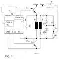
- the engine control unit M supplies the ignition output stage E with a pulse-width-modulated signal PMW in , the pulse duty factor signaling the desired primary current I 1set and the duration of the signal representing the desired charging time.
- a signal in digital form with a corresponding information content can also be fed to the ignition stage.
- the ignition output stage E then regulates the primary current to the value specified by the control signal.
- a charging transistor L is driven, which is arranged on the primary side in front of the ignition coil.
- a further transistor Z is provided, which is also controlled by the ignition output stage E. If the primary current is interrupted by the transistor Z, the primary-side magnetic field collapses very quickly and generates a high voltage by induction in the secondary winding S. If this exceeds the breakdown voltage, a spark jumps over the spark plug and the fuel-air mixture is ignited between the electrodes of the spark plug.
- a capacitor K is also provided on the secondary side, which is provided as a voltage source for an ion current measurement between the electrodes of the spark plug. The capacitor is charged by the ignition pulses.
- the ion current is then tapped via a voltage divider formed from the resistors R1 and R2 and fed to an amplifier V, which can also be arranged on the ignition coil in order to minimize the signal path up to the amplifier V.
- the signals are then amplified to such an extent that they are not noticeably disturbed on the way to the engine control unit M by any interference signals that may occur.
- the evaluation of the ion current signal I ion by the engine control unit M then enables, for example, detection of the knocking of the corresponding engine or detection of misfires.
- the engine control unit M has, inter alia, a characteristic curve which indicates the switch-on time depending on the battery voltage.
- a map is also provided, which indicates the charging current as a function of load and speed.
- a Speed dynamic compensation as is usually provided in engine control units, is provided on the other hand, no longer necessary if the time of regulated operation is long enough. Furthermore, load dynamic compensation is provided as a factor, with one Multiplication by the charging current from the basic map is carried out.
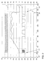
- Fig. 2 are the control signal originating from the engine control unit, the Control signals for the charging transistor L and the ignition transistor Z and the course of the Primary current shown.
- the control signal 1 is pulse-width modulated, the Duty cycle signals the desired primary current and the duration of the signal indicates the desired charging time.
- the primary coil is charged.
- the Charging transistor L temporarily temporarily blocked during the period L1 and switched through.
- the primary current 4 After the primary current 4 is switched on in a damped manner, this initially rises approximately linearly up to a setpoint specified by the control signal 1. After reaching this setpoint, the primary current is then regulated during the Time L2 by suitable control of the charging transistor L. Disables the Charging transistor L, the primary current drops. However, in this case the primary circuit is closed via the diode D, the current can initially according to Lenz's rule continue to flow so that the current drop is dampened. Then the charging transistor L switched through again so that the primary current again up to the predetermined setpoint can increase. With this regulation, the primary current until the ignition at the time Z2 limited to the specified setpoint.
- the invention has several advantages. So can by regulating the primary current Power loss can be significantly reduced. Furthermore, the switch-on spark suppression possible without using an HV diode. This in turn makes it easy to and way to make an ion current measurement. Finally, the charging current Independent of battery voltage, and there is no need for speed dynamic compensation.
Landscapes
- Engineering & Computer Science (AREA)
- Chemical & Material Sciences (AREA)
- Combustion & Propulsion (AREA)
- Mechanical Engineering (AREA)
- General Engineering & Computer Science (AREA)
- Ignition Installations For Internal Combustion Engines (AREA)
Applications Claiming Priority (2)
| Application Number | Priority Date | Filing Date | Title |
|---|---|---|---|
| DE19957350 | 1999-11-29 | ||
| DE19957350 | 1999-11-29 |
Publications (3)
| Publication Number | Publication Date |
|---|---|
| EP1103720A2 true EP1103720A2 (fr) | 2001-05-30 |
| EP1103720A3 EP1103720A3 (fr) | 2002-06-05 |
| EP1103720B1 EP1103720B1 (fr) | 2007-05-16 |
Family
ID=7930687
Family Applications (1)
| Application Number | Title | Priority Date | Filing Date |
|---|---|---|---|
| EP00125290A Expired - Lifetime EP1103720B1 (fr) | 1999-11-29 | 2000-11-27 | Procédé et dispositif pour la commande du courant d'un circuit d'allumage de moteur à combustion |
Country Status (2)
| Country | Link |
|---|---|
| EP (1) | EP1103720B1 (fr) |
| DE (1) | DE50014331D1 (fr) |
Cited By (2)
| Publication number | Priority date | Publication date | Assignee | Title |
|---|---|---|---|---|
| US6837230B2 (en) * | 2002-07-22 | 2005-01-04 | Mitsubishi Denki Kabushiki Kaisha | Ignition device for an internal combustion engine |
| WO2011113431A1 (fr) * | 2010-03-17 | 2011-09-22 | Motortech Gmbh | Procédé d'allumage et installation d'allumage pour ce procédé |
Family Cites Families (3)
| Publication number | Priority date | Publication date | Assignee | Title |
|---|---|---|---|---|
| JPS59171219A (ja) * | 1983-03-17 | 1984-09-27 | Nec Corp | レベル検出回路 |
| JPH02245478A (ja) * | 1989-03-20 | 1990-10-01 | Mitsubishi Electric Corp | 内燃機関点火装置 |
| US5723916A (en) * | 1996-05-17 | 1998-03-03 | Delco Electronics Corporation | Electrical load driving device including load current limiting circuitry |
-
2000
- 2000-11-27 EP EP00125290A patent/EP1103720B1/fr not_active Expired - Lifetime
- 2000-11-27 DE DE50014331T patent/DE50014331D1/de not_active Expired - Lifetime
Cited By (3)
| Publication number | Priority date | Publication date | Assignee | Title |
|---|---|---|---|---|
| US6837230B2 (en) * | 2002-07-22 | 2005-01-04 | Mitsubishi Denki Kabushiki Kaisha | Ignition device for an internal combustion engine |
| WO2011113431A1 (fr) * | 2010-03-17 | 2011-09-22 | Motortech Gmbh | Procédé d'allumage et installation d'allumage pour ce procédé |
| US8893692B2 (en) | 2010-03-17 | 2014-11-25 | Motortech Gmbh | Ignition method and ignition system therefor |
Also Published As
| Publication number | Publication date |
|---|---|
| DE50014331D1 (de) | 2007-06-28 |
| EP1103720A3 (fr) | 2002-06-05 |
| EP1103720B1 (fr) | 2007-05-16 |
Similar Documents
| Publication | Publication Date | Title |
|---|---|---|
| DE2340865C3 (de) | Zündvorrichtung für eine Brennkraftmaschine | |
| EP0790406B1 (fr) | Système d'allumage électronique pour moteurs à combustion interne | |
| DE4234847C2 (de) | Verfahren zur Zündungssteuerung einer Brennkraftmaschine und Kondensator-Zündvorrichtung zur Durchführung des Verfahrens | |
| DE2606890C2 (de) | Hochleistungszündanlage für Brennkraftmaschinen | |
| EP0640761B2 (fr) | Dispositif d'allumage commandable | |
| EP1254313B1 (fr) | Procede pour produire une serie d'etincelles d'allumage haute tension et dispositif d'allumage haute tension | |
| EP0034787A1 (fr) | Système d'allumage pour moteurs à combustion interne | |
| WO2012130649A1 (fr) | Procédé et dispositif de prolongement de la durée de combustion d'une étincelle allumée par une bougie d'allumage dans un moteur à combustion interne | |
| DE2747819A1 (de) | Verfahren und schaltungsanordnung zum steuern des primaerstromes in spulenzuendanlagen von kraftfahrzeugen | |
| DE2753255C2 (de) | Zündanlage für Brennkraftmaschinen | |
| DE1920884C3 (de) | Zündeinrichtung für eine Brennkraftmaschine | |
| EP0489264B1 (fr) | Système d'allumage électronique | |
| DE3924985C2 (fr) | ||
| DE2619556A1 (de) | Zuendanlage, insbesondere fuer brennkraftmaschinen | |
| DE2700676C2 (de) | Zündanlage für Brennkraftmaschinen | |
| DE2736576C2 (de) | Zündanlage mit einer mechanisch nicht bewegten Hochspannungsverteilung für Brennkraftmaschinen | |
| EP1103720B1 (fr) | Procédé et dispositif pour la commande du courant d'un circuit d'allumage de moteur à combustion | |
| DE2417878B2 (de) | Zuendanordnung fuer brennkraftmaschinen | |
| DE2424896A1 (de) | Zuendeinrichtung fuer eine brennkraftmaschine | |
| DE2527725B2 (de) | Schaltungsanordnung für Brennkraftmaschinen-Zündeinrichtungen | |
| DE102012218698B3 (de) | Vorrichtung und Verfahren zum Zünden einer Zündkerze eines Kraftfahrzeugs | |
| EP1280993A2 (fr) | Systeme d'allumage pour moteur a combustion interne | |
| DE2531302A1 (de) | Zuendeinrichtung fuer brennkraftmaschinen | |
| DE19927960A1 (de) | Zündvorrichtung und Zündverfahren für Brennkraftmaschinen | |
| DE3040509A1 (de) | Zuendeinrichtung fuer brennkraftmaschinen |
Legal Events
| Date | Code | Title | Description |
|---|---|---|---|
| PUAI | Public reference made under article 153(3) epc to a published international application that has entered the european phase |
Free format text: ORIGINAL CODE: 0009012 |
|
| AK | Designated contracting states |
Kind code of ref document: A2 Designated state(s): AT BE CH CY DE DK ES FI FR GB GR IE IT LI LU MC NL PT SE TR |
|
| AX | Request for extension of the european patent |
Free format text: AL;LT;LV;MK;RO;SI |
|
| PUAL | Search report despatched |
Free format text: ORIGINAL CODE: 0009013 |
|
| AK | Designated contracting states |
Kind code of ref document: A3 Designated state(s): AT BE CH CY DE DK ES FI FR GB GR IE IT LI LU MC NL PT SE TR |
|
| AX | Request for extension of the european patent |
Free format text: AL;LT;LV;MK;RO;SI |
|
| RIC1 | Information provided on ipc code assigned before grant |
Free format text: 7F 02P 17/12 A, 7F 02P 3/05 B |
|
| 17P | Request for examination filed |
Effective date: 20021205 |
|
| AKX | Designation fees paid |
Designated state(s): DE ES FR GB IT |
|
| GRAP | Despatch of communication of intention to grant a patent |
Free format text: ORIGINAL CODE: EPIDOSNIGR1 |
|
| GRAS | Grant fee paid |
Free format text: ORIGINAL CODE: EPIDOSNIGR3 |
|
| GRAA | (expected) grant |
Free format text: ORIGINAL CODE: 0009210 |
|
| AK | Designated contracting states |
Kind code of ref document: B1 Designated state(s): DE ES FR GB IT |
|
| REG | Reference to a national code |
Ref country code: GB Ref legal event code: FG4D Free format text: NOT ENGLISH |
|
| REF | Corresponds to: |
Ref document number: 50014331 Country of ref document: DE Date of ref document: 20070628 Kind code of ref document: P |
|
| PG25 | Lapsed in a contracting state [announced via postgrant information from national office to epo] |
Ref country code: ES Free format text: LAPSE BECAUSE OF FAILURE TO SUBMIT A TRANSLATION OF THE DESCRIPTION OR TO PAY THE FEE WITHIN THE PRESCRIBED TIME-LIMIT Effective date: 20070827 |
|
| GBV | Gb: ep patent (uk) treated as always having been void in accordance with gb section 77(7)/1977 [no translation filed] |
Effective date: 20070516 |
|
| EN | Fr: translation not filed | ||
| PLBE | No opposition filed within time limit |
Free format text: ORIGINAL CODE: 0009261 |
|
| STAA | Information on the status of an ep patent application or granted ep patent |
Free format text: STATUS: NO OPPOSITION FILED WITHIN TIME LIMIT |
|
| 26N | No opposition filed |
Effective date: 20080219 |
|
| PG25 | Lapsed in a contracting state [announced via postgrant information from national office to epo] |
Ref country code: GB Free format text: LAPSE BECAUSE OF FAILURE TO SUBMIT A TRANSLATION OF THE DESCRIPTION OR TO PAY THE FEE WITHIN THE PRESCRIBED TIME-LIMIT Effective date: 20070516 Ref country code: IT Free format text: LAPSE BECAUSE OF FAILURE TO SUBMIT A TRANSLATION OF THE DESCRIPTION OR TO PAY THE FEE WITHIN THE PRESCRIBED TIME-LIMIT Effective date: 20070516 |
|
| PG25 | Lapsed in a contracting state [announced via postgrant information from national office to epo] |
Ref country code: FR Free format text: LAPSE BECAUSE OF FAILURE TO SUBMIT A TRANSLATION OF THE DESCRIPTION OR TO PAY THE FEE WITHIN THE PRESCRIBED TIME-LIMIT Effective date: 20080111 |
|
| PGFP | Annual fee paid to national office [announced via postgrant information from national office to epo] |
Ref country code: DE Payment date: 20161130 Year of fee payment: 17 |
|
| REG | Reference to a national code |
Ref country code: DE Ref legal event code: R119 Ref document number: 50014331 Country of ref document: DE |
|
| REG | Reference to a national code |
Ref country code: DE Ref legal event code: R082 Ref document number: 50014331 Country of ref document: DE |
|
| PG25 | Lapsed in a contracting state [announced via postgrant information from national office to epo] |
Ref country code: DE Free format text: LAPSE BECAUSE OF NON-PAYMENT OF DUE FEES Effective date: 20180602 |