EP1103729A1 - Vorrichtung zum Verbinden von länglichen Profilen - Google Patents
Vorrichtung zum Verbinden von länglichen Profilen Download PDFInfo
- Publication number
- EP1103729A1 EP1103729A1 EP99123429A EP99123429A EP1103729A1 EP 1103729 A1 EP1103729 A1 EP 1103729A1 EP 99123429 A EP99123429 A EP 99123429A EP 99123429 A EP99123429 A EP 99123429A EP 1103729 A1 EP1103729 A1 EP 1103729A1
- Authority
- EP
- European Patent Office
- Prior art keywords
- pressure element
- joint
- sleeve
- sleeves
- outer sleeve
- Prior art date
- Legal status (The legal status is an assumption and is not a legal conclusion. Google has not performed a legal analysis and makes no representation as to the accuracy of the status listed.)
- Withdrawn
Links
- 230000000295 complement effect Effects 0.000 claims description 2
- 238000010276 construction Methods 0.000 claims description 2
- 230000000694 effects Effects 0.000 description 3
- 229920002430 Fibre-reinforced plastic Polymers 0.000 description 2
- 239000013013 elastic material Substances 0.000 description 2
- 239000011151 fibre-reinforced plastic Substances 0.000 description 2
- 230000006835 compression Effects 0.000 description 1
- 238000007906 compression Methods 0.000 description 1
- 230000007423 decrease Effects 0.000 description 1
- 230000002542 deteriorative effect Effects 0.000 description 1
- 239000000463 material Substances 0.000 description 1
- 230000003068 static effect Effects 0.000 description 1
Images

Classifications
-
- F—MECHANICAL ENGINEERING; LIGHTING; HEATING; WEAPONS; BLASTING
- F16—ENGINEERING ELEMENTS AND UNITS; GENERAL MEASURES FOR PRODUCING AND MAINTAINING EFFECTIVE FUNCTIONING OF MACHINES OR INSTALLATIONS; THERMAL INSULATION IN GENERAL
- F16B—DEVICES FOR FASTENING OR SECURING CONSTRUCTIONAL ELEMENTS OR MACHINE PARTS TOGETHER, e.g. NAILS, BOLTS, CIRCLIPS, CLAMPS, CLIPS OR WEDGES; JOINTS OR JOINTING
- F16B2/00—Friction-grip releasable fastenings
- F16B2/02—Clamps, i.e. with gripping action effected by positive means other than the inherent resistance to deformation of the material of the fastening
- F16B2/14—Clamps, i.e. with gripping action effected by positive means other than the inherent resistance to deformation of the material of the fastening using wedges
-
- F—MECHANICAL ENGINEERING; LIGHTING; HEATING; WEAPONS; BLASTING
- F16—ENGINEERING ELEMENTS AND UNITS; GENERAL MEASURES FOR PRODUCING AND MAINTAINING EFFECTIVE FUNCTIONING OF MACHINES OR INSTALLATIONS; THERMAL INSULATION IN GENERAL
- F16B—DEVICES FOR FASTENING OR SECURING CONSTRUCTIONAL ELEMENTS OR MACHINE PARTS TOGETHER, e.g. NAILS, BOLTS, CIRCLIPS, CLAMPS, CLIPS OR WEDGES; JOINTS OR JOINTING
- F16B2/00—Friction-grip releasable fastenings
- F16B2/02—Clamps, i.e. with gripping action effected by positive means other than the inherent resistance to deformation of the material of the fastening
- F16B2/04—Clamps, i.e. with gripping action effected by positive means other than the inherent resistance to deformation of the material of the fastening internal, i.e. with spreading action
-
- E—FIXED CONSTRUCTIONS
- E04—BUILDING
- E04B—GENERAL BUILDING CONSTRUCTIONS; WALLS, e.g. PARTITIONS; ROOFS; FLOORS; CEILINGS; INSULATION OR OTHER PROTECTION OF BUILDINGS
- E04B1/00—Constructions in general; Structures which are not restricted either to walls, e.g. partitions, or floors or ceilings or roofs
- E04B1/38—Connections for building structures in general
- E04B1/58—Connections for building structures in general of bar-shaped building elements
- E04B1/5825—Connections for building structures in general of bar-shaped building elements with a closed cross-section
- E04B2001/5856—Connections for building structures in general of bar-shaped building elements with a closed cross-section using the innerside thereof
-
- E—FIXED CONSTRUCTIONS
- E04—BUILDING
- E04B—GENERAL BUILDING CONSTRUCTIONS; WALLS, e.g. PARTITIONS; ROOFS; FLOORS; CEILINGS; INSULATION OR OTHER PROTECTION OF BUILDINGS
- E04B1/00—Constructions in general; Structures which are not restricted either to walls, e.g. partitions, or floors or ceilings or roofs
- E04B1/38—Connections for building structures in general
- E04B1/58—Connections for building structures in general of bar-shaped building elements
- E04B2001/5868—Hinged connections
Definitions
- the invention relates to a device for connecting elongated, bored profiles, in particular for trade fair and shop construction, with two connected by a joint essentially cylindrical parts by means of driven wedges generated forces spread apart are, each with a pull rod that has a first Pressure element on a side of the cylindrical adjacent to the joint Partly a pressure force, and a second pressure element, that exerts pressure on the other side when a wedge is driven, each cylindrical part being one inner sleeve that can be energized by a thrust washer and has an outer sleeve.
- Devices of this type are in large numbers for connection of tubes and hollow profiles known, each a cylindrical Part inserted into a tube or hollow profile and then is spread apart (EP 0 501 148 A1, DE 37 37 171 C2, DE 38 27 142 C2). But it is also what an unusual use such devices, known, represents a device of the type mentioned above for connecting profiles to use that are provided with holes that are vertical are aligned to the longitudinal extent of the profiles (EP 0 870 879 A2).
- the rubber-elastic material can tire or wear out over time deteriorate in quality. It also allows because its elasticity is not a particularly stable connection Profiles.
- the object of the invention is to provide a device on possibly deteriorating rubber elastic Materials dispensed and a safe positive Allows connection between the profiles.
- the solution according to the invention is that the inner Sleeve several adjoining, frustoconical Surface sections and the outer sleeve one or more Hollow cylinder segments with complementary frustoconical Has inner surfaces and held together by one or more rings is, and both sleeves when a wedge is driven is acted upon by a pressure element with pressure force become.
- the frustoconical surface sections of the inner Sleeve can move outwards (towards the joint) rejuvenate or expand.
- the first printing element on the inner sleeve and the second pressure element on the outer sleeve In the other case it is the other way around.
- the rings are expediently O-rings.
- the device can be easily released again when the profiles are to be separated from one another is expedient provided that the sleeves against the direction in which they can be acted upon by spring force are biased.
- This spring force is ineffective when the Wedges are driven in and the outer sleeves spread outwards are. But if the wedges are removed, they press Spring the sleeves back to their rest position in the axial direction, which reduces the diameter of the outer sleeve, so that the direction is easy from the holes of the profiles can be removed.
- the sleeves are expediently made of fiber-reinforced plastic, where it has proven to be particularly useful if only the outer sleeves made of fiber-reinforced plastic are.
- the opening angle of the truncated cones depends on the material determined according to the limit of static friction so that the Device can also be detached from the profiles. It is advisable to choose an opening angle for the truncated cones, which is approximately 4 ° to 30 ° (i.e. an angle from 2 ° to 15 ° between the cylinder axis and the truncated cone surface). However, it has proven to be particularly useful that the opening angle of the truncated cones is approximately 8 ° to Amount to 12 °.
- both tie rods are connected to a joint part are and the first pressure element of a cylindrical part with Game is arranged and can be pressed against the other joint part is. If the wedges are then driven in, it will not just spread the outer sleeve to anchor to the Effect profiles. Rather, the two joint parts pressed against each other and thereby in the current Angular position locked.
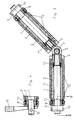
- Fig. 1 consists essentially of two cylindrical parts, each a tie rod 1, one inner sleeve 2 slidably disposed thereon and an outer sleeve Have sleeve 3.
- the outer sleeve 3 consists of a or more, in particular three or more hollow cylinder segments, so that it can expand radially.
- the inner one Sleeve 2 is with frustoconical surface sections, which connect directly to each other. Corresponding frustoconical Sections faces on their inner surface the outer sleeve 3.
- On the left in Fig. 1 is a first disc-shaped pressure element 4 with an axial Game attached.
- the pull rod 1 is on the pin 5 of the joint attached, with which the two parts are connected are.
- the first pressure element 6 is firmly on the pull rod 1 attached.
- the pull rod 1 of the right part and the first pressure element 6 of this part are rigid with the Joint eye 7 of the central joint connected.
- On the two There are second disc-shaped pressure elements 8 at the ends, that can slide on the relevant drawbar 1.
- This second pressure elements 8 can be in the direction of the joint 5, 7 are pressed by as shown in FIG the ends fork-shaped wedges 9 are driven, the support on a pin 10. This creates a pulling force the corresponding tie rod 1 and the first pressure elements 4 or 6 pulled out while the second Pressure elements 8 are pressed inwards.
- the first printing elements 4, 6 move the outer sleeves 3 outwards, while the second pressure elements 8 follow the inner sleeves 2 Press inside, the frustoconical surface sections slide on each other, causing the outer sleeves 3 be expanded. This allows the profiles to be attached to each other become. Should the profiles be separated from each other again the wedges 9 are removed. Press compression springs 11 the inner sleeves 2 and the outer sleeves 3 counter the direction in which they were energized back so that the diameter of the outer sleeves 3 decreases, so that the device from the holes of the profiles can be pulled out again. Through 0-rings 12 will finally ensured that the hollow cylinder segments the sleeve 3 can not detach from the device.
- the first pressure element (4) of the left part sits axially movable on the pull rod 1. If the wedge 9 on the left side is driven by the pull of the pull rod 1 pressed the pressure element 4 against the hinge part 7 and therefore locks the joint in this position. As from the It can be seen that there is an angle with this embodiment from 0 ° to 45 ° between the two parts of the device possible.
- FIGS. 3 and 4 corresponds essentially the embodiment of FIGS. 1 and 2 with the difference that the first pressure elements 4, 6 are somewhat different are so that swivel angle of 30 ° to 90 ° between the two profile parts are possible.
Landscapes
- Engineering & Computer Science (AREA)
- General Engineering & Computer Science (AREA)
- Mechanical Engineering (AREA)
- Mutual Connection Of Rods And Tubes (AREA)
Abstract
Description
- Fig. 1
- eine erste Ausführungsform der Erfindung im Querschnitt;
- Fig. 2
- einen Schnitt entlang der Linie II-II von Fig. 1;
- Fig. 3
- eine zweite Ausführungsform der Erfindung im Querschnitt; und
- Fig. 4
- einen Schnitt entlang der Linie IV-IV von Fig. 3.
Claims (10)
- Vorrichtung zum Verbinden von länglichen, mit Bohrungen versehenen Profilen, insbesondere für den Messe- und Ladenbau, mit zwei durch ein Gelenk (5, 7) verbundenen im wesentlichen zylindrischen Teilen, die durch mittels eingetriebenen Keilen (9) erzeugten Kräften auseinanderspreizbar sind, mit je einer Zugstange (1), die über ein erstes Druckelement (4) auf einer dem Gelenk (5, 7) benachbarten Seite des zylindrischen Teils eine Druckkraft, und einem zweiten Druckelement (8), das auf die andere Seite eine Druckkraft ausübt, wenn ein Keil (9) eingetrieben ist, wobei jeder zylindrische Teil eine innere Hülse (2) und eine äußere Hülse (3) aufweist, dadurch gekennzeichnet, daß die innere Hülse (2) mehrere aneinander anschließende kegelstumpfförmige Oberflächenabschnitte aufweist und die äußere Hülse (3) ein oder mehrere Hohlzylindersegmente mit komplementären kegelstumpfförmigen Innenflächen aufweist und durch einen oder mehrere Ringe (12) zusammengehalten ist und beide Hülsen (2, 3), wenn ein Keil (9) eingetrieben ist, durch je ein Druckelement (4, 6, 8) mit Druckkraft beaufschlagt werden.
- Vorrichtung nach Anspruch 1, dadurch gekennzeichnet, daß die kegelstumpfförmigen Oberflächenabschnitte der inneren Hülse (2) sich nach der vom Gelenk (5, 7) entfernten Seite im Durchmesser verringern und die innere Hülse (2) vom ersten Druckelement (4, 6) und die äußere Hülse (3) vom zweiten Druckelement (8) mit Druckkraft beaufschlagbar ist.
- Vorrichtung nach Anspruch 1, dadurch gekennzeichnet, daß die kegelstumpfförmigen Oberflächenabschnitte der inneren Hülse (2) sich nach der vom Gelenk (5, 7) entfernten Seite im Durchmesser vergrößern und die äußere Hülse (3) vom ersten Druckelement (4, 6) und die innere Hülse (2) vom zweiten Druckelement (8) mit Druckkraft beaufschlagbar ist.
- Vorrichtung nach einem der Ansprüche 1-3, dadurch gekennzeichnet, daß die Ringe (12) O-Ringe sind.
- Vorrichtung nach einem der Ansprüche 1-4, dadurch gekennzeichnet, daß die Hülsen (2, 3) entgegen der Richtung in der sie mit Kraft beaufschlagbar sind, durch Federkraft (11) vorgespannt sind.
- Vorrichtung nach einem der Ansprüche 1 bis 5, dadurch gekennzeichnet, daß die Hülsen (2, 3) aus faserverstärktem Kunststoff sind.
- Vorrichtung nach einem der Ansprüche 1 bis 5, dadurch gekennzeichnet, daß die äußeren Hülsen (3) aus faserverstärktem Kunststoff sind.
- Vorrichtung nach einem der Ansprüche 1 bis 7, dadurch gekennzeichnet, daß der Öffnungswinkel der Kegelstümpfe ungefähr 4° bis 30° beträgt.
- Vorrichtung nach einem der Ansprüche 1 bis 8, dadurch gekennzeichnet, daß der Öffnungswinkel der Kegelstümpfe ungefähr 8° bis 12° beträgt.
- Vorrichtung nach einem der Ansprüche 1 bis 8, dadurch gekennzeichnet, daß beide Zugstangen (1) mit je einem Gelenkteil (5, 7) verbunden sind und die erste Druckelement (4) eines zylindrischen Teils mit Spiel angeordnet ist und gegen den anderen Gelenkteil (7) drückbar ist.
Priority Applications (2)
| Application Number | Priority Date | Filing Date | Title |
|---|---|---|---|
| EP99123429A EP1103729A1 (de) | 1999-11-24 | 1999-11-24 | Vorrichtung zum Verbinden von länglichen Profilen |
| DE29924517U DE29924517U1 (de) | 1999-11-24 | 1999-11-24 | Vorrichtung zum Verbinden von länglichen Profilen |
Applications Claiming Priority (1)
| Application Number | Priority Date | Filing Date | Title |
|---|---|---|---|
| EP99123429A EP1103729A1 (de) | 1999-11-24 | 1999-11-24 | Vorrichtung zum Verbinden von länglichen Profilen |
Publications (1)
| Publication Number | Publication Date |
|---|---|
| EP1103729A1 true EP1103729A1 (de) | 2001-05-30 |
Family
ID=8239456
Family Applications (1)
| Application Number | Title | Priority Date | Filing Date |
|---|---|---|---|
| EP99123429A Withdrawn EP1103729A1 (de) | 1999-11-24 | 1999-11-24 | Vorrichtung zum Verbinden von länglichen Profilen |
Country Status (1)
| Country | Link |
|---|---|
| EP (1) | EP1103729A1 (de) |
Citations (6)
| Publication number | Priority date | Publication date | Assignee | Title |
|---|---|---|---|---|
| BE525461A (de) * | ||||
| DE2711845A1 (de) * | 1977-03-18 | 1978-09-21 | Fritz Thoma | Duebel |
| DE3737171C2 (de) | 1987-11-03 | 1989-11-09 | Klaus Dipl.-Ing. 4800 Bielefeld De Westerheide | |
| EP0501148A1 (de) | 1991-02-26 | 1992-09-02 | Hewi Heinrich Wilke Gmbh | Verbindungssystem für zwei als Rohr- oder Stangen- und/oder Knotenelemente ausgebildete Bauteile |
| DE3827142C2 (de) | 1988-08-10 | 1995-03-09 | Ulrich Kreusel | Gelenkverbindung für Rohre |
| EP0870879A2 (de) | 1997-04-07 | 1998-10-14 | Preuss Messebaugesellschaft mbH | Bausatz für den Messe- und Ladenbau |
-
1999
- 1999-11-24 EP EP99123429A patent/EP1103729A1/de not_active Withdrawn
Patent Citations (6)
| Publication number | Priority date | Publication date | Assignee | Title |
|---|---|---|---|---|
| BE525461A (de) * | ||||
| DE2711845A1 (de) * | 1977-03-18 | 1978-09-21 | Fritz Thoma | Duebel |
| DE3737171C2 (de) | 1987-11-03 | 1989-11-09 | Klaus Dipl.-Ing. 4800 Bielefeld De Westerheide | |
| DE3827142C2 (de) | 1988-08-10 | 1995-03-09 | Ulrich Kreusel | Gelenkverbindung für Rohre |
| EP0501148A1 (de) | 1991-02-26 | 1992-09-02 | Hewi Heinrich Wilke Gmbh | Verbindungssystem für zwei als Rohr- oder Stangen- und/oder Knotenelemente ausgebildete Bauteile |
| EP0870879A2 (de) | 1997-04-07 | 1998-10-14 | Preuss Messebaugesellschaft mbH | Bausatz für den Messe- und Ladenbau |
Similar Documents
| Publication | Publication Date | Title |
|---|---|---|
| DE1750663C3 (de) | Ankerschraube | |
| DE69302685T2 (de) | Schwenkverbindungsglied | |
| DE3732628C1 (de) | Aufweitewerkzeug fuer hohle Werkstuecke | |
| DE4030978C2 (de) | Verbindungseinrichtung für Rohre | |
| EP0752230A2 (de) | Putzgerät | |
| EP0475216A1 (de) | Schraubverbindung zwischen Stäben und Knotenstücken eines Raumfachwerkes oder dergleichen | |
| DE2630891C3 (de) | Vorrichtung zum Verbinden eines mit einem Aufweitkonus versehenen Erdverdrängungshammers mit einem Nachziehrohr | |
| DE3300227A1 (de) | Vorrichtung zur loesbaren verbindung von greiferschienenteilen der greiferschienen in einer transfer-presse | |
| DE3611617C1 (de) | Vorrichtung zur Ioesbaren Arretierung eines Bolzens | |
| DE2425800B2 (de) | Vorrichtung zur Befestigung einer Elektrodenhalterung einer Funkenerosionsmaschine | |
| EP0215771B1 (de) | Zusammenlegbarer Gehstock | |
| DE9316464U1 (de) | Spannvorrichtung zum Dehnen von Schrauben | |
| DE19806965B4 (de) | Klemm- und Trennvorrichtung, insb. zum Abziehen von Lagerschalen dienende Vorrichtung | |
| DE10245235B4 (de) | Spannsatz | |
| EP2110208B1 (de) | Teleskopstiel mit Arretiereinrichtung | |
| DE3408863C1 (de) | Druckaufbaudorn zum Befestigen eines Rohres in einem Rohrboden od. dgl. | |
| DE3539612C1 (de) | Vorrichtung zur Erzielung eines loesbaren Presssitzes zwischen einem Bauteil mit zylindrischer Bohrung und einem in diese Bohrung eingefuehrten Bauteil | |
| DE8904751U1 (de) | Aufweitvorrichtung für geschlitzte Klemmbohrungen | |
| DE2852420C2 (de) | Futterwürfelpresse | |
| DE3910644C2 (de) | ||
| DE4018042C2 (de) | Vorrichtung zum Verbinden von zwei stumpf gestoßenen Bewehrungsstäben mittels einer Muffe | |
| DE69502863T2 (de) | Radial aufweitbares Befestigungselement | |
| DE29924517U1 (de) | Vorrichtung zum Verbinden von länglichen Profilen | |
| DE3317146A1 (de) | Keilgetriebe | |
| DE102022118953B4 (de) | Springseil mit Seilkupplungen |
Legal Events
| Date | Code | Title | Description |
|---|---|---|---|
| PUAI | Public reference made under article 153(3) epc to a published international application that has entered the european phase |
Free format text: ORIGINAL CODE: 0009012 |
|
| AK | Designated contracting states |
Kind code of ref document: A1 Designated state(s): AT BE CH CY DE DK ES FI FR GB GR IE IT LI LU MC NL PT SE |
|
| AX | Request for extension of the european patent |
Free format text: AL;LT;LV;MK;RO;SI |
|
| 17P | Request for examination filed |
Effective date: 20010530 |
|
| AKX | Designation fees paid |
Free format text: AT BE CH CY DE DK ES FI FR GB GR IE IT LI LU MC NL PT SE |
|
| 17Q | First examination report despatched |
Effective date: 20030227 |
|
| STAA | Information on the status of an ep patent application or granted ep patent |
Free format text: STATUS: THE APPLICATION HAS BEEN WITHDRAWN |
|
| 18W | Application withdrawn |
Effective date: 20030527 |