EP1103731A1 - Dispositif pour pour montage dans une ouverture de un panneau - Google Patents
Dispositif pour pour montage dans une ouverture de un panneau Download PDFInfo
- Publication number
- EP1103731A1 EP1103731A1 EP00650199A EP00650199A EP1103731A1 EP 1103731 A1 EP1103731 A1 EP 1103731A1 EP 00650199 A EP00650199 A EP 00650199A EP 00650199 A EP00650199 A EP 00650199A EP 1103731 A1 EP1103731 A1 EP 1103731A1
- Authority
- EP
- European Patent Office
- Prior art keywords
- hinged
- body portion
- panel
- operative position
- aperture
- Prior art date
- Legal status (The legal status is an assumption and is not a legal conclusion. Google has not performed a legal analysis and makes no representation as to the accuracy of the status listed.)
- Withdrawn
Links
- 230000001419 dependent effect Effects 0.000 claims abstract description 4
- 229920003023 plastic Polymers 0.000 claims description 3
- 239000004033 plastic Substances 0.000 claims description 3
- 239000012530 fluid Substances 0.000 claims 1
- 239000002184 metal Substances 0.000 description 3
- 230000014509 gene expression Effects 0.000 description 1
- 239000000463 material Substances 0.000 description 1
- 238000000465 moulding Methods 0.000 description 1
Images

Classifications
-
- F—MECHANICAL ENGINEERING; LIGHTING; HEATING; WEAPONS; BLASTING
- F16—ENGINEERING ELEMENTS AND UNITS; GENERAL MEASURES FOR PRODUCING AND MAINTAINING EFFECTIVE FUNCTIONING OF MACHINES OR INSTALLATIONS; THERMAL INSULATION IN GENERAL
- F16B—DEVICES FOR FASTENING OR SECURING CONSTRUCTIONAL ELEMENTS OR MACHINE PARTS TOGETHER, e.g. NAILS, BOLTS, CIRCLIPS, CLAMPS, CLIPS OR WEDGES; JOINTS OR JOINTING
- F16B5/00—Joining sheets or plates, e.g. panels, to one another or to strips or bars parallel to them
- F16B5/06—Joining sheets or plates, e.g. panels, to one another or to strips or bars parallel to them by means of clamps or clips
-
- E—FIXED CONSTRUCTIONS
- E06—DOORS, WINDOWS, SHUTTERS, OR ROLLER BLINDS IN GENERAL; LADDERS
- E06B—FIXED OR MOVABLE CLOSURES FOR OPENINGS IN BUILDINGS, VEHICLES, FENCES OR LIKE ENCLOSURES IN GENERAL, e.g. DOORS, WINDOWS, BLINDS, GATES
- E06B7/00—Special arrangements or measures in connection with doors or windows
- E06B7/14—Measures for draining-off condensed water or water leaking-in frame members for draining off condensation water, throats at the bottom of a sash
-
- E—FIXED CONSTRUCTIONS
- E06—DOORS, WINDOWS, SHUTTERS, OR ROLLER BLINDS IN GENERAL; LADDERS
- E06B—FIXED OR MOVABLE CLOSURES FOR OPENINGS IN BUILDINGS, VEHICLES, FENCES OR LIKE ENCLOSURES IN GENERAL, e.g. DOORS, WINDOWS, BLINDS, GATES
- E06B7/00—Special arrangements or measures in connection with doors or windows
- E06B7/28—Other arrangements on doors or windows, e.g. door-plates, windows adapted to carry plants, hooks for window cleaners
-
- F—MECHANICAL ENGINEERING; LIGHTING; HEATING; WEAPONS; BLASTING
- F16—ENGINEERING ELEMENTS AND UNITS; GENERAL MEASURES FOR PRODUCING AND MAINTAINING EFFECTIVE FUNCTIONING OF MACHINES OR INSTALLATIONS; THERMAL INSULATION IN GENERAL
- F16B—DEVICES FOR FASTENING OR SECURING CONSTRUCTIONAL ELEMENTS OR MACHINE PARTS TOGETHER, e.g. NAILS, BOLTS, CIRCLIPS, CLAMPS, CLIPS OR WEDGES; JOINTS OR JOINTING
- F16B37/00—Nuts or like thread-engaging members
- F16B37/04—Devices for fastening nuts to surfaces, e.g. sheets, plates
- F16B37/041—Releasable devices
- F16B37/043—Releasable devices with snap action
Definitions
- This invention relates to a device for fitting to a panel having at least one aperture.
- a device for fitting to a panel having at least one aperture comprising a body portion having a base for placing against one surface of the panel adjacent to the aperture and at least two dependent retaining elements for extending downwardly through the aperture and laterally under the edge thereof to bear against the panel, wherein at least one of the retaining elements is hinged to the body portion for rotation from an inoperative position in which the hinged element is retracted inwardly to allow the retaining elements to be inserted into the aperture to an operative position in which the hinged element bears against the panel as aforesaid, the hinged element having means for engaging the said one surface of the panel as the base of the body portion is brought towards the said one surface such that the hinged element is automatically rotated from the inoperative to the operative position, the device further including means for latching the hinged element to the body portion in the operative position of the hinged element.
- the hinged retaining element depends from an enlarged root portion which rotates into a cavity in the body portion as the element is rotated from the inoperative to the operative position, the said engaging means being a surface formed at the junction of the root portion and the hinged element.
- orientation such as “top”, “bottom”, “base”, “downwardly”, etc., are used for convenience of description and do not limit the orientation of the device in use.
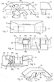
- the device 100 is a one-piece plastics moulding and includes an elongate body portion 10 having a flat base 12 and two dependent retaining elements 14, 16 each adjacent a respective opposite end of the body portion.
- the element 16 is fixed relative to the body portion and extends downwardly and laterally outwardly therefrom.
- the element 14 depends from an enlarged root portion 18 having a part-cylindrical outer surface 20.
- the root portion 18 is integrally joined to the base 12 of the body portion 10 by a narrow flexible web 22 of the plastics material which acts as a hinge so that the element 14 is rotatable from an inoperative position (shown in solid lines in Fig. 1) where the element 14 is retracted inwardly towards the centre of the body portion, to an operative position (shown in dashed lines in Figs. 1 and 3 and in solid lines in Figs. 4 to 6) where the element 14, like the element 16, extends downwardly and laterally outwardly from the body portion 10.
- the root portion 18 rotates into a cavity 24 in the body portion, the cavity 24 having a part-cylindrical inner surface 26 along which the outer surface 20 of the root portion slides.
- the root portion has a surface 28 having portions 28a, 28b extending laterally on each side of the element 14.
- the surface 28 is flush with the base 12 of the body portion 10.
- the element 14 has a downwardly and outwardly inclined outer surface 15; the element 16 has a downwardly and outwardly inclined outer surface 17.
- the elements 14, 16 have respective feet 14a, 16a which extend, when the element 14 is in its operative position, mutually away from one another and at least whose upper surfaces, i.e. those surfaces closest to the body 10, are substantially parallel to the base 12 of the body 10.
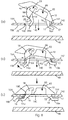
- Figs. 7(a) to 7(c) illustrate how the device is fitted to an aperture 40 in a first thickness of panel 42 (the aperture 40 is also shown in plan view in dashed lines in Fig. 4).
- the aperture 40 has opposite end walls 50, 52.
- the panel 42 has an upper surface 54 and a lower surface 56.
- the aperture 40 is a slot having a width just greater than the width of the elements 14 and 16, to allow them to pass through, but not as wide as the surface 28.
- Fig. 7(a) the hinged element 14 is rotated to its inoperative retracted position and, holding the body portion 10, the fixed element 16 is manually manoeuvred around and under one end of the slot 40, i.e. the right hand end in the view shown.
- the left hand end of the body portion 10 is pushed down and at some point, Fig. 7(b), the lateral portions 28a, 28b of the surface 28 will engage the upper surface 54 of the panel 42 on the opposite edges of the slot 40 since, as stated, the width of the surface 28 is greater than the width of the slot 40.
- Fig. 7(c) the surface 28 is flush with the base 12 of the body portion 10, the base 12 is flush with the upper surface 54 of the panel 42, and the element 14 is in its operative position.
- the elements 14, 16 extend downwardly through the slot 40 and mutually away from one another laterally under the edge of the slot 40 at opposite ends thereof.
- the depth of the retaining elements 14, 16 is so chosen in relation to the thickness of the panel 42 that in the final operative position of the device 100 the upper surfaces of the feet 14a, 16a of the elements 14, 16 come to bear against the lower surface 56 of the panel 42, so holding the device firmly in place on the panel.
- a projection 44 on the root portion 18 snap-engages a corresponding recess 46 in the cavity surface 26 just as the element 14 reaches its operative position.
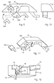
- Figs. 8(a) to 8(c), which correspond to those of Figs. 7(a) to 7(c), illustrate how the device 100 is fitted to an aperture 140 in a second panel 142 having a thickness less than the first panel 42.
- the aperture 140 has opposite end walls 150, 152.
- the panel 142 has an upper surface 154 and a lower surface 156.
- the end wall 150 and the lower surface 156 define an arris 70; the end wall 152 and the lower surface 156 define an arris 72.
- the aperture 140 is a slot having a width just greater than the width of the elements 14 and 16, to allow them to pass through, but not as wide as the surface 28.
- the manner of fitting the device 100 to the panel 142 is the same as previously described for the panel 42, except that since the thickness of the panel 142 is less than that of the panel 42 the feet 14a, 14b cannot come to bear on the lower surface 56 of the panel 142 in the final operative position of the device 100 because the distance between the upper surfaces of the feet 14a, 16a and the base 12 of the body 10 is greater than the thickness of the panel 142. Consequently, in this case the length of the aperture 140, i.e. the distance between its end walls 150 and 152, is made less than the corresponding length of the aperture 40 so that, in the final operative position of the device 100, Fig.
- the described device is capable of being securely fitted to the slot 40 in the panel 42 even where a second panel 48 is close to the first panel 40 and prevents access to the rear of the first panel.
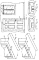
- a typical application for the device is to cover a drainage slot 62, Fig. 13, in a hollow metal window frame 64.
- the body portion 10 has a cavity 66 (Figs. 1 to 12) which is open both at the base 12 and the side 60 of the body portion 10, the device being fitted to the window frame with the side 60 facing down.
- a hook 70 to the body portion 10, Fig. 15, or to provide the body portion 10 with a threaded bore 72, Fig. 16, to receive some other fitting.
- Such devices could be used, for example, to fit a hook to a hollow metal door 74, Fig. 17, or to fit a curtain rail 76.
- the device has been described for use with a single aperture or slot 40, it is evident that the device could be fitted to a panel having two apertures, the element 16 being inserted in one of the apertures and the element 14 in the other. Further, it is not necessary that the aperture 40 be a slot, provided that the aperture is so shaped as to present, in the vicinity of the element 14, an edge or edges capable of catching the surface 28 (or any equivalent surface) and thereby rotating the element 14 to its operative position. It is also envisaged that the device could have two or more hinged elements 14, again provided that the aperture was suitably shaped to catch the surface 28 and rotate the element 14 to its operative position.
- the device may also have more than one fixed element 16, or all the retaining elements of the device may be hinged elements 14. For example, it is clear that the device described herein would work effectively if the element 16 were a hinged element constructed similarly to the element 14.
Landscapes
- Engineering & Computer Science (AREA)
- General Engineering & Computer Science (AREA)
- Civil Engineering (AREA)
- Structural Engineering (AREA)
- Mechanical Engineering (AREA)
- Hinges (AREA)
- Connection Of Plates (AREA)
Applications Claiming Priority (2)
| Application Number | Priority Date | Filing Date | Title |
|---|---|---|---|
| IE990991 | 1999-11-26 | ||
| IE990991 | 1999-11-26 |
Publications (1)
| Publication Number | Publication Date |
|---|---|
| EP1103731A1 true EP1103731A1 (fr) | 2001-05-30 |
Family
ID=11042169
Family Applications (1)
| Application Number | Title | Priority Date | Filing Date |
|---|---|---|---|
| EP00650199A Withdrawn EP1103731A1 (fr) | 1999-11-26 | 2000-11-23 | Dispositif pour pour montage dans une ouverture de un panneau |
Country Status (2)
| Country | Link |
|---|---|
| EP (1) | EP1103731A1 (fr) |
| IE (1) | IES20000959A2 (fr) |
Cited By (2)
| Publication number | Priority date | Publication date | Assignee | Title |
|---|---|---|---|---|
| EP1518987A1 (fr) * | 2003-09-27 | 2005-03-30 | Roto Frank Ag | Fenêtre, porte ou similaire avec un accessoire muni de dispositif de fixation |
| EP1519057A1 (fr) | 2003-09-25 | 2005-03-30 | Scania CV AB (publ) | Dispositif de fixation |
Citations (4)
| Publication number | Priority date | Publication date | Assignee | Title |
|---|---|---|---|---|
| US4579478A (en) * | 1984-12-24 | 1986-04-01 | Nifco Inc. | Sheet part fixing device |
| GB2168419A (en) * | 1984-12-13 | 1986-06-18 | Tucker Fasteners Ltd | Plastics clip |
| US4850773A (en) * | 1987-05-27 | 1989-07-25 | Nifco, Inc. | Clip |
| EP0837252A1 (fr) * | 1996-09-23 | 1998-04-22 | MAGNA EXTERIOR SYSTEMS GmbH | Elément de fixation |
-
2000
- 2000-11-23 EP EP00650199A patent/EP1103731A1/fr not_active Withdrawn
- 2000-11-23 IE IE20000959A patent/IES20000959A2/en not_active IP Right Cessation
Patent Citations (4)
| Publication number | Priority date | Publication date | Assignee | Title |
|---|---|---|---|---|
| GB2168419A (en) * | 1984-12-13 | 1986-06-18 | Tucker Fasteners Ltd | Plastics clip |
| US4579478A (en) * | 1984-12-24 | 1986-04-01 | Nifco Inc. | Sheet part fixing device |
| US4850773A (en) * | 1987-05-27 | 1989-07-25 | Nifco, Inc. | Clip |
| EP0837252A1 (fr) * | 1996-09-23 | 1998-04-22 | MAGNA EXTERIOR SYSTEMS GmbH | Elément de fixation |
Cited By (2)
| Publication number | Priority date | Publication date | Assignee | Title |
|---|---|---|---|---|
| EP1519057A1 (fr) | 2003-09-25 | 2005-03-30 | Scania CV AB (publ) | Dispositif de fixation |
| EP1518987A1 (fr) * | 2003-09-27 | 2005-03-30 | Roto Frank Ag | Fenêtre, porte ou similaire avec un accessoire muni de dispositif de fixation |
Also Published As
| Publication number | Publication date |
|---|---|
| IES20000959A2 (en) | 2001-05-30 |
Similar Documents
| Publication | Publication Date | Title |
|---|---|---|
| US4235465A (en) | Burglarproof guard for window lock | |
| US6250730B1 (en) | Safety device for drawers | |
| US3997205A (en) | Cabinet door clip | |
| US6311935B1 (en) | Cable clamp | |
| US4471981A (en) | Personal security lock | |
| US20080295285A1 (en) | Hinge pin for enclosure | |
| EP1103731A1 (fr) | Dispositif pour pour montage dans une ouverture de un panneau | |
| US5709422A (en) | Security device for double doors | |
| CA1165372A (fr) | Pince a ressort en resine synthetique | |
| ES2065250A2 (es) | Charnela de ala base de fijacion rapida para la misma. | |
| US5297829A (en) | Security lock for door | |
| EP0400189A1 (fr) | Couvercle de protection pour porte d'enceinte | |
| ES2239183T3 (es) | Herraje para un elemento de cierre de una abertura en un muro. | |
| FR2783550B1 (fr) | Serrure a decondamnation automatique a l'ouverture | |
| WO2001033128A1 (fr) | Dispositif de support | |
| EP0804662B1 (fr) | Structure de moule pour tubes noyes | |
| SK282756B6 (sk) | Vyklápacie zariadenie na okná, dvere alebo podobne | |
| FR2475107A1 (fr) | Dispositif de fixation d'un chassis de porte, notamment pour une porte de garage | |
| US1061866A (en) | Keyhole-closer. | |
| JPH047296Y2 (fr) | ||
| WO1999027217A1 (fr) | Dispositif de calage de battant en position d'ouverture utilisable comme patere et comme cale traditionnelle | |
| IES83284Y1 (en) | A device for fitting to a panel | |
| JPS5829228Y2 (ja) | 手掛け | |
| IES20010976A2 (en) | A Device for Fitting to a Panel | |
| KR100892550B1 (ko) | 절단 방지가 가능한 셔트용 체결구 |
Legal Events
| Date | Code | Title | Description |
|---|---|---|---|
| PUAI | Public reference made under article 153(3) epc to a published international application that has entered the european phase |
Free format text: ORIGINAL CODE: 0009012 |
|
| AK | Designated contracting states |
Kind code of ref document: A1 Designated state(s): AT BE CH CY DE DK ES FI FR GB GR IE IT LI LU MC NL PT SE TR |
|
| AX | Request for extension of the european patent |
Free format text: AL;LT;LV;MK;RO;SI |
|
| 17P | Request for examination filed |
Effective date: 20011130 |
|
| AKX | Designation fees paid |
Free format text: AT BE CH CY DE DK ES FI FR GB GR IE IT LI LU MC NL PT SE TR |
|
| STAA | Information on the status of an ep patent application or granted ep patent |
Free format text: STATUS: THE APPLICATION IS DEEMED TO BE WITHDRAWN |
|
| 18D | Application deemed to be withdrawn |
Effective date: 20030603 |