EP1103748B1 - Aufblasventil - Google Patents
Aufblasventil Download PDFInfo
- Publication number
- EP1103748B1 EP1103748B1 EP00125245A EP00125245A EP1103748B1 EP 1103748 B1 EP1103748 B1 EP 1103748B1 EP 00125245 A EP00125245 A EP 00125245A EP 00125245 A EP00125245 A EP 00125245A EP 1103748 B1 EP1103748 B1 EP 1103748B1
- Authority
- EP
- European Patent Office
- Prior art keywords
- valve
- piston
- actuator
- housing
- inflation valve
- Prior art date
- Legal status (The legal status is an assumption and is not a legal conclusion. Google has not performed a legal analysis and makes no representation as to the accuracy of the status listed.)
- Expired - Lifetime
Links
- 230000001105 regulatory effect Effects 0.000 claims description 9
- 239000012530 fluid Substances 0.000 claims description 5
- 238000004891 communication Methods 0.000 claims description 4
- 238000007789 sealing Methods 0.000 claims 1
- 230000007246 mechanism Effects 0.000 description 12
- 230000001276 controlling effect Effects 0.000 description 2
- 230000004913 activation Effects 0.000 description 1
- 238000007792 addition Methods 0.000 description 1
- 230000008859 change Effects 0.000 description 1
- 238000010276 construction Methods 0.000 description 1
- 230000007423 decrease Effects 0.000 description 1
- 238000004519 manufacturing process Methods 0.000 description 1
- 238000012986 modification Methods 0.000 description 1
- 230000004048 modification Effects 0.000 description 1
- 230000004044 response Effects 0.000 description 1
Images

Classifications
-
- F—MECHANICAL ENGINEERING; LIGHTING; HEATING; WEAPONS; BLASTING
- F16—ENGINEERING ELEMENTS AND UNITS; GENERAL MEASURES FOR PRODUCING AND MAINTAINING EFFECTIVE FUNCTIONING OF MACHINES OR INSTALLATIONS; THERMAL INSULATION IN GENERAL
- F16K—VALVES; TAPS; COCKS; ACTUATING-FLOATS; DEVICES FOR VENTING OR AERATING
- F16K15/00—Check valves
- F16K15/20—Check valves specially designed for inflatable bodies, e.g. tyres
-
- B—PERFORMING OPERATIONS; TRANSPORTING
- B63—SHIPS OR OTHER WATERBORNE VESSELS; RELATED EQUIPMENT
- B63C—LAUNCHING, HAULING-OUT, OR DRY-DOCKING OF VESSELS; LIFE-SAVING IN WATER; EQUIPMENT FOR DWELLING OR WORKING UNDER WATER; MEANS FOR SALVAGING OR SEARCHING FOR UNDERWATER OBJECTS
- B63C9/00—Life-saving in water
- B63C9/02—Lifeboats, life-rafts or the like, specially adapted for life-saving
- B63C9/04—Life-rafts
- B63C2009/042—Life-rafts inflatable
-
- B—PERFORMING OPERATIONS; TRANSPORTING
- B63—SHIPS OR OTHER WATERBORNE VESSELS; RELATED EQUIPMENT
- B63C—LAUNCHING, HAULING-OUT, OR DRY-DOCKING OF VESSELS; LIFE-SAVING IN WATER; EQUIPMENT FOR DWELLING OR WORKING UNDER WATER; MEANS FOR SALVAGING OR SEARCHING FOR UNDERWATER OBJECTS
- B63C9/00—Life-saving in water
- B63C9/24—Arrangements of inflating valves or of controls thereof
Definitions
- the present invention relates to valves and, more particularly, to an inflation valve for controlling the flow of pressurized gas in the inflation of inflatable devices such as aircraft emergency evacuation slides and rafts.
- Inflation valves find extensive use in controlling the flow of a stored pressurized gas to a variety of inflatable devices such as emergency evacuation slides for aircraft, life rafts, crash bags, and the like.
- U.S. Patent No. 5,009,249 to Fisher et al. discloses a pressure regulator for regulating an inflatable member such as a slide.
- the pressure regulator includes a spool valve balanced between a trigger mechanism on one end and a spring on the other. Actuating the trigger mechanism on one end causes the spool valve to be unseated by a first spring and thereby placed in a pressure regulating position by a second spring in opposition to the escaping fluid pressure acting on the valve.
- the first spring biases the spool valve to interconnect the outlet with the gas storage, and the second spring regulates the gas flow from storage to outlet in response to pressure change at the outlet.
- U.S. Patent No. 4,549,870 to Wass discloses a raft inflation valve having a pin that provides a stop at one end of a spool valve and a spring at the other. Removing the pin allows the spring to urge the spool valve into an open position, thereby enabling inflation of the raft.
- the piston remains in the open position regardless of the pressure present within the valve during raft inflation.
- the raft inflation valve does not include integral means to return the piston in its closed position.
- US-3.204.926 discloses an inflation valve, a piston of which is biased towards a valve seat. As long as that inflation valve should remain closed, the piston is mechanically arrested as regards its movements away from the valve seat. For opening that inflation valve, the mechanical arrest of the piston is removed and the piston is allowed to move away from the valve seat. The movement of the piston away from the valve seat is effected by pressure within the inflation valve, which pushes the piston away from the valve seat.
- FR-A-2.088.830 discloses an inflation valve having a piston.
- the piston For opening that inflation valve, the piston is moved away from a valve seat thereby opening an outlet port.
- This movement of the piston is effected by pressures originating from a pyrotechnical cartridge.
- the pyrotechnical cartridge Upon activation, the pyrotechnical cartridge builds up pressure acting on one end of the piston thereby pushing the piston in a direction away from the valve seat.
- valve openings are based on forces provided and generated internally within the inflation valves.
- forces for opening these inflation valves are provided by springs within the valves or pressure built up within the valves effecting piston movements away from valve seats. In case, these forces cannot be provided internally within the valves, it is not possible to open these valves.
- opening of an inflation valve is required in an emergency case, such a failure can represent a severe problem.
- the approach of the above inflation valves to employ internally provided forces for valve openings requires respective valve components, which lead to complex designs, increased fabrication costs and itself represents possible failure sources.
- an inflation valve inflation valve comprising a valve housing having an inner wall, a cylindrical inner chamber, a gas outlet, and a gas inlet bore providing fluid communication between the inner chamber and a pressurized gas source, a piston enclosed in the inner chamber comprises at one end a head directed toward the gas outlet and at the opposite end a valve actuator connector, a gas inlet seal, positioned between the head and the actuator connector, that releasably seals the gas inlet bore from the inner chamber when the piston is in a normal non-actuated position and a valve actuator connected to the actuator connector is provided, wherein, according to the present invention, a regulating spring contacts the piston close to the actuator connector is compressible by the force of pressure exerted by gas contained within the inner chamber and gas inlet bore and operates to position the piston to control or regulate the outlet pressure, the cylindrical inner chamber terminates in the gas outlet and the valve actuator operates to pull the piston, thereby moving the gas inlet seal away from the gas inlet bore and putting the inner chamber in fluid communication with the gas
- an inflation valve 100 of the present invention includes a valve housing 101 having an inner wall 102 and a cylindrical inner chamber 103.
- a gas inlet bore 104 leading from a compressed gas source (not shown) intersects inner chamber 103.
- a piston 105 is enclosed by inner wall 102 of valve housing 101.
- Piston 105 includes at one end an actuator connector 106, to which is attached a valve actuator 107.
- At the other end of the piston 105 is a piston head 108 that engages with an outlet bore 109 at a gas outlet 110 that is disposed at one end of valve housing 101.
- Gas outlet 110 is connected to an inflatable device such as an aircraft emergency slide (not shown).
- Piston 105 is also provided with a gas inlet seal land 111 positioned between actuator connector 106 and piston head 108 and equipped with two O-ring seals 112a and 112b. If desired, O-ring seal 112a can be mounted at a corresponding position on piston 105 rather than on inner wall 102.
- gas seal land 111 and O-ring seals 112a and 112b prevent the flow of gas from gas inlet bore 104 to inner chamber 103. Operation of valve actuator 107 by pulling causes piston 105 to move within inner wall 102 of housing 101, unsealing gas inlet bore 104 and allowing gas to flow into the inner chamber 103 and thence to outlet 110.
- valve housing 101 The end of valve housing 101 opposite gas outlet 110 is closed by an actuator housing 113 that guides valve actuator 107.
- Regulating spring 114 connects actuator housing 113 and the end of piston 105 nearest actuator 107.
- spring 114 When gas is discharged into inner chamber 103 by operation of actuator 107 to move piston 105, spring 114 is compressed.
- the force of the pressure on piston 105 which diminishes as the discharged gas exits outlet 110, is counteracted by a substantially equal opposing force from compressed spring 114, causing piston 105 to return towards its original non-actuated position as the gas pressure at inlet bore 104 is reduced.
- inflation valve 100 can be provided with a safety lock mechanism that includes a detent 115 and a safety release pin 116. Before valve actuator 107 can be operated, pin 116 must be removed, which allows piston 105 to move within housing 101.
- valve actuator 107 can comprise a cable or rod 117 terminated by a ball 118, and actuator connector 106 can be a socket for retaining ball 118.
- the term "pulling" as applied to operating valve actuator 107 is employed to describe the mechanical moving of piston 105 toward actuator housing 113 and away from gas outlet 110.
- a handle (not shown) could be connected to actuator 107 in a way that would cause an individual operating valve 100 to exert a "pushing" force that nonetheless results in “pulling” of piston 105 toward housing 113 and away from outlet 110, as described.
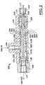
- FIG. 2 is a front cross-sectional view of a valve 200 in accordance with the present invention.
- Valve 200 differs from the previously described valve 100 in having a piston comprising two components and a positive lock mechanism. However most of the elements of valve 100 are also contained for the same respective purposes in valve 200, including valve housing 101 having inner wall 102 and inner chamber 103, gas inlet bore 104, actuator connector 106, valve actuator 107, piston head 108, outlet bore 109 at gas outlet 110, gas seal land 111, O-ring seals 112a and 112b, actuator housing 113, regulating spring 114, cable or rod 117, and ball 118.
- valve 200 further includes a piston 201 that comprises two interconnecting components 202 and 203.
- First piston component 202 includes piston head 108, gas seal land 111, and O-ring seals 112a and 112b, while second piston component 203 includes actuator connector 106, valve actuator 107, regulating spring 114, cable or rod 117, and ball 118.
- Piston components 202 and 203 are interconnected by corresponding flanges 204 and 205, respectively.
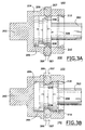
- Piston component 203 further includes at its juncture with component 202 a positive lock mechanism comprising detents 206 that, in their non-actuated, i.e., locked position, are disposed in a groove 207 in inner wall 102 of valve housing 101. The elements and operation of the lock mechanism will be described with reference to FIGS. 3A and 3B.
- FIG. 3A is shown the lock mechanism in its non-actuated, i.e., locked position, wherein detents 206 are held in place by piston second component 203 and thus prevent movement of piston first component 202.
- Pulling operation of valve actuator 107 which is connected to second component 203 as shown in FIG. 2, causes component 203 to move away from first component 202 and allows detents 206, which preferably have rounded surfaces and can be spherical in shape, to exit groove 207 and slide down ramps 208 of flange 205, as shown in FIG. 3B.
- second piston component 203 In its actuated, unlocked position, second piston component 203 is free to move along with interconnected first component 202 as the pulling operation of actuator 107 is continued.
- a snap ring 209 can be inserted in an annular groove 210 in housing inner wall 102 to serve as a stop for the lateral motion of flange 205 when second piston component 203 is caused to move by the pulling operation of valve actuator 107.
- Movement of interconnected components 202 and 203 of piston 201 results in unsealing of gas inlet bore 104, allowing gas to flow into the inner chamber 103 and thence to outlet 110.
- the force of the pressure on piston 205 of valve 200 which diminishes as the discharged gas exits outlet 110, is counteracted by a substantially equal opposing force from compressed spring 114, causing piston 205 to return towards its original non-actuated position as the gas pressure at inlet bore 104 decreases.
- the inflation valve of the present invention is desirably simple in its construction and operation.
- the trigger mechanism is kept to a minimum, including at one end a cable or rod that pulls directly on the valve piston, which is held in its normal, inactuated position by O-rings and a safety lock mechanism.
- the cable or rod When the cable or rod is pulled, the pressure from the pressurized tank opens the valve, the flow of gas being regulaled by the inlet pressure from the pressurized gas source and regulating spring at the end of the piston opposite the gas outlet to an inflatable device.
Landscapes
- Engineering & Computer Science (AREA)
- General Engineering & Computer Science (AREA)
- Mechanical Engineering (AREA)
- Preventing Unauthorised Actuation Of Valves (AREA)
- Fluid-Driven Valves (AREA)
- Quick-Acting Or Multi-Walled Pipe Joints (AREA)
Claims (17)
- Aufblasventil (100), mit:gekennzeichnet durcheinem Ventilgehäuse (101) mit einer Innenwand (102), einer zylindrischen Innenkammer (103), einem Gasauslass (110) und einer Gaseinlassbohrung (104), die für eine Fluidverbindung zwischen der Innenkammer (103) und einer unter Druck gesetzten Gasquelle sorgt;einem in der Innenkammer (103) eingeschlossenen Kolben (105), wobei der Kolben (105) an einem Ende einen in Richtung zu dem Gasauslass (110) gerichteten Boden (108) und an dem gegenüberliegenden Ende einen Ventilaktuatoranschluss (106) umfasst, wobei der Kolben (105) ferner eine Gaseinlassdichtung (111) umfasst, die zwischen dem Boden (108) und dem Aktuatoranschluss (106) angeordnet ist, wobei die Dichtung (111) die Gaseinlassbohrung (104) gegenüber der Innenkammer (103) lösbar abdichtet, wenn sich der Kolben (105) in einer normalen nicht betätigten Position befindet; undeinem Ventilaktuator (107), der mit dem Aktuatoranschluss (106) verbunden ist,die zylindrische Innenkammer (103), die in dem Gasauslass (110) endet,wenigstens einer Rückholfeder (114), die den Kolben (105) in der Nähe des Aktuatoranschlusses (106) berührt, wobei die Feder (114) durch die Kraft von Druck zusammendrückbar ist, der von in der Innenkammer (103) enthaltenem Gas ausgeübt wird, und wirkt, um den Kolben (105) in Richtung zu dessen normaler nicht betätigter Position zurückzubringen, undden Ventilaktuator (107), der wirksam ist, den Kolben (105) zu ziehen, wodurch die Gaseinlassdichtung (111) weg von der Gaseinlassbohrung (105) bewegt und die Innenkammer (103) in Fluidverbindung mit der Gaseinlassbohrung (104) und der unter Druck gesetzten Gasquelle gebracht werden.
- Aufblasventil (100) nach Anspruch 1, bei dem der Gasauslass (110) ferner einen Auslasssitz zur Wirkverbindung mit dem Kolbenboden umfasst.
- Aufblasventil (100) nach Anspruch 1, bei dem die Gaseinlassdichtung (111) wenigstens einen an dem Kolben (105) angeordnete O-Ring-Dichtung (112a, 112b) umfasst.
- Aufblasventil (100) nach Anspruch 3, bei dem die Gaseinlassdichtung (111) ferner eine an der Innenwand (102) des Gehäuses (101) angeordnete O-Ring-Dichtung umfasst.
- Aufblasventil (100) nach Anspruch 1, ferner mit einem Aktuatorgehäuse (113), das das Ende des Ventilgehäuses (101) gegenüber dem Gasauslass (110) verschließt.
- Aufblasventil (100) nach Anspruch 5, bei dem Rückholfeder (114) durch das Aktuatorgehäuse (101) gefesselt ist.
- Aufblasventil (100) nach Anspruch 1, bei dem der Ventilaktuator (107) eine mit dem Anschluss (106) verbundene Stange oder Kabel (117) umfasst.
- Aufblasventil (100) nach Anspruch 7, bei dem der Ventilaktuator (106) in einer Kugel (118) endet und der Anschluss (106) eine Kugelaufnahme ist.
- Aufblasventil (100) nach Anspruch 1, ferner mit einer Sicherheitsarretierung, um eine unbeabsichtigte Betätigung des Ventils (100) zu verhindern.
- Aufblasventil (100) nach Anspruch 9, bei dem die Sicherheitsarretierung einen sich durch das Ventilgehäuse (101) erstreckenden Sicherheitsfreigabestift (116) und eine einrückbare Arretierung (115) in dem Gehäuse (101) im Wesentlichen diametral gegenüberliegend dem Sicherheitsfreigabestift (116) umfasst, wobei die einrückbare Arretierung (115) eine Bewegung des Kolbens (105) in dem Gehäuse (101) verhindert, bis der Stift (116) gelöst ist.
- Aufblasventil (100) nach Anspruch 1, bei dem der Kolben (201) erste und zweite miteinander verbindende Komponenten (202, 203) umfasst.
- Aufblasventil (100) nach Anspruch 11, bei dem die ersten und zweiten Kolbenkomponenten (202, 203) durch entsprechende Flansche (204, 205) an den Komponenten (202, 203) miteinander verbunden sind.
- Aufblasventil (100) nach Anspruch 12, bei dem die erste Komponente (202) den Kolbenboden (108) und die Gaseinlassdichtung (111) umfasst, und die zweite Komponente (203) den Aktuatoranschluss (106) umfasst, wobei der Anschluss (106) mit dem Ventilaktuator (107) verbunden ist.
- Aufblasventil (100) nach Anspruch 13, bei dem die zweite Kolbenkomponente (203) ferner eine Sicherheitsarretierung umfasst, um eine unbeabsichtigte Betätigung des Ventils (100) zu verhindern.
- Aufblasventil (100) nach Anspruch 14, bei dem die Arretierung einrückbare Arretierungen (206) umfasst, die an dem Flansch (205) der zweiten Kolbenkomponente (203) angeordnet sind, wobei sich die einrückbaren Arretierungen (206) in Aussparungen (207) in der Innenwand (102) des Gehäuses (101) erstrecken, wenn sich die Arretierung in einer nicht betätigten, arretierten Position befindet.
- Aufblasventil (100) nach Anspruch 15, bei dem der Flansch (205) der zweiten Kolbenkomponente (203) ferner Rampen (208) benachbart zu den einrückbaren Arretierungen (206) umfasst, wobei die einrückbaren Arretierungen (206) bei Betrieb des Ventilaktuators (107) veranlasst werden, die Aussparungen (207) in der Gehäuseinnenwand (102) zu verlassen und sich die Rampen (208) hinter zu bewegen, wodurch die Arretierung in eine betätigte, nicht arretierte Position gebracht wird und die miteinander verbindenden Komponenten (202, 203) des Kolbens (201) in die Lage versetzt werden, sich in dem Gehäuse (101) zu bewegen.
- Aufblasventil (100) nach Anspruch 12, ferner mit einem Sprengring (209), der in einer ringförmigen Nut (210) der Innenwand (102) des Ventilgehäuses (101) angeordnet ist, wobei der Sprengring (209) wirkt, um eine laterale Bewegung des Flansches (205) der zweiten Kolbenkomponente (203) zu beenden, die von einer Ziehwirkung des Ventilaktuators (107) herrührt.
Applications Claiming Priority (2)
| Application Number | Priority Date | Filing Date | Title |
|---|---|---|---|
| US09/448,997 US6467751B1 (en) | 1999-11-24 | 1999-11-24 | Inflation valve |
| US448997 | 1999-11-24 |
Publications (3)
| Publication Number | Publication Date |
|---|---|
| EP1103748A2 EP1103748A2 (de) | 2001-05-30 |
| EP1103748A3 EP1103748A3 (de) | 2002-08-21 |
| EP1103748B1 true EP1103748B1 (de) | 2004-08-18 |
Family
ID=23782467
Family Applications (1)
| Application Number | Title | Priority Date | Filing Date |
|---|---|---|---|
| EP00125245A Expired - Lifetime EP1103748B1 (de) | 1999-11-24 | 2000-11-23 | Aufblasventil |
Country Status (3)
| Country | Link |
|---|---|
| US (1) | US6467751B1 (de) |
| EP (1) | EP1103748B1 (de) |
| DE (1) | DE60013073T2 (de) |
Families Citing this family (18)
| Publication number | Priority date | Publication date | Assignee | Title |
|---|---|---|---|---|
| US7886731B2 (en) * | 2002-03-06 | 2011-02-15 | Kee Action Sports I Llc | Compressed gas gun having reduced breakaway-friction and high pressure dynamic separable seal flow control device |
| US7237545B2 (en) | 2002-03-06 | 2007-07-03 | Aj Acquisition I Llc | Compressed gas-powered projectile accelerator |
| US8413644B2 (en) | 2002-03-06 | 2013-04-09 | Kee Action Sports I Llc | Compressed gas gun having reduced breakaway-friction and high pressure dynamic separable seal and flow control and valving device |
| US6684670B1 (en) * | 2002-08-07 | 2004-02-03 | Inner-Tite Corp. | Lock assembly with self retained barrel lock |
| WO2004038268A1 (en) * | 2002-10-23 | 2004-05-06 | Stopak (Pty) Ltd. | Inflation valve |
| US7258138B2 (en) * | 2005-01-11 | 2007-08-21 | Dale Carpenter | Methods and apparatus for an on-off controller |
| US20080276668A1 (en) | 2005-06-03 | 2008-11-13 | Stachowiak Jr John Edward | Retained lock system and method |
| ITRM20050465A1 (it) * | 2005-09-12 | 2007-03-13 | Aero Sekur S P A | Valvola perfezionata per un contenitore, preferibilmente per una bombola contenente gas ad alta pressione. |
| US20080217573A1 (en) * | 2007-03-06 | 2008-09-11 | Timothy George Pulcini | Poppet cartridge with two-piece poppet and piston coupled by a floating coupler |
| US9452409B2 (en) * | 2011-04-22 | 2016-09-27 | Vanderbilt University | Para-hydrogen polarizer |
| GB201515123D0 (en) * | 2015-08-26 | 2015-10-07 | Smiths Medical Int Ltd | Valves and tubes including valves |
| US9725177B2 (en) | 2015-10-20 | 2017-08-08 | Ami Industries, Inc. | Pneumatic comfort seats |
| US9945488B2 (en) * | 2015-11-10 | 2018-04-17 | Goodrich Corporation | Mechanically-activated inflation valve actuation apparatus |
| US10293949B2 (en) * | 2016-01-20 | 2019-05-21 | Goodrich Corporation | Inflation system pressure regulator with leakage vent |
| CN108591485B (zh) * | 2018-05-31 | 2024-07-02 | 北京万高众业科技股份有限公司 | 一种检测连接阀及具有其的碳滑板流通性检测装置 |
| CN109812606B (zh) * | 2019-04-02 | 2024-02-09 | 威海旭日过滤器股份有限公司 | 一种排气阀 |
| US11162599B2 (en) | 2019-06-14 | 2021-11-02 | Goodrich Corporation | Valve for aircraft inflation system |
| CN116750171B (zh) * | 2023-05-23 | 2026-04-24 | 三峡大学 | 水面下开口筒形件自动上浮回收装置及使用方法 |
Family Cites Families (41)
| Publication number | Priority date | Publication date | Assignee | Title |
|---|---|---|---|---|
| US232008A (en) * | 1880-09-07 | John demaeest | ||
| US1320441A (en) * | 1919-11-04 | baillie | ||
| US184279A (en) * | 1876-11-14 | Improvement in faucets | ||
| US1771122A (en) * | 1928-10-01 | 1930-07-22 | Ted R Jay | Safety gas valve |
| US2749941A (en) * | 1950-06-01 | 1956-06-12 | Evelyn M Gardner | Rotary fluid control valve |
| US2884954A (en) * | 1957-03-25 | 1959-05-05 | Frederick S Roberts | Gasoline economizer valve |
| US3023773A (en) * | 1958-11-10 | 1962-03-06 | Clark Equipment Co | Regulating valve |
| US3204926A (en) * | 1961-12-21 | 1965-09-07 | Specialties Dev Corp | Valve control mechanism |
| US3308850A (en) | 1964-10-01 | 1967-03-14 | Gen Pneumatic Corp | Cable actuated multi-fitting gas valves |
| US3570805A (en) | 1969-01-31 | 1971-03-16 | Switlik Parachute Co Inc | Valve having quick release fluid pressure valve closing means |
| US3559689A (en) * | 1969-07-14 | 1971-02-02 | Bendix Corp | 20 man raft co2 inflation valve |
| GB1276063A (en) * | 1970-02-03 | 1972-06-01 | Kidde Walter Co Ltd | Diversion valve |
| US3602245A (en) * | 1970-02-26 | 1971-08-31 | Abex Corp | Universal detent positioner |
| FR2088830A5 (de) * | 1970-04-27 | 1972-01-07 | Aerazur Constr Aeronaut | |
| US3702623A (en) * | 1970-08-31 | 1972-11-14 | Sargent Industries | Fluid pressure regulation mechanism having upslope regulating characteristics |
| FR2140925A5 (de) * | 1971-06-09 | 1973-01-19 | Citroen Sa | |
| US3790129A (en) * | 1971-07-15 | 1974-02-05 | Cessna Aircraft Co | Valve detent mechanism |
| US3802012A (en) * | 1972-04-19 | 1974-04-09 | W Middleton | Fluid pressure sensing devices |
| US3860984A (en) | 1973-06-25 | 1975-01-21 | Goodrich Co B F | Inflatable life raft escape slide |
| US4168720A (en) | 1976-03-03 | 1979-09-25 | General Pneumatics Corporation | Poppet valve |
| US4061158A (en) * | 1976-11-22 | 1977-12-06 | Musial George J | Valve with combination lock and remote control |
| US4215715A (en) | 1979-02-22 | 1980-08-05 | General Pneumatics Corporation | Poppet valve |
| US4566862A (en) | 1982-02-23 | 1986-01-28 | General Pneumatics Corporation | Fluid apparatus and methods, as for inflating inflatable structures |
| US4549870A (en) | 1983-08-22 | 1985-10-29 | Wass Lloyd G | Raft inflation valve |
| US4595374A (en) * | 1983-04-13 | 1986-06-17 | Wass Lloyd G | Raft inflation valve |
| US4633957A (en) * | 1985-04-15 | 1987-01-06 | Prost Claude D | Soil plugger with plug ejector |
| FR2614669B1 (fr) * | 1987-04-29 | 1989-07-13 | Gratzmuller Claude | Valve hydraulique a trois voies |
| US4860788A (en) * | 1987-06-29 | 1989-08-29 | Kayaba Industry Co. Ltd. | Metering valve |
| US4757840A (en) * | 1987-07-27 | 1988-07-19 | Deere & Company | Multipiece spool valve |
| CA1315324C (en) * | 1988-03-16 | 1993-03-30 | Peter Kooiman | Flow control device |
| US4959034A (en) * | 1988-10-25 | 1990-09-25 | Wass Lloyd G | Puncture disc inflation valve with improved cutting bayonet |
| US5009249A (en) | 1990-04-16 | 1991-04-23 | The B. F. Goodrich Company | Valve for fluid container |
| US5169119A (en) | 1991-03-08 | 1992-12-08 | The Boeing Company | Mechanism for releasing stored gas from a pressure vessel |
| US5131427A (en) * | 1991-08-06 | 1992-07-21 | Flint Hydraulic, Inc. | Pilot operated relief valve |
| US5113891A (en) * | 1991-10-31 | 1992-05-19 | Carney Frederick P | Water freeze guard valve |
| US5205538A (en) * | 1991-12-09 | 1993-04-27 | Caterpillar Inc. | Detent mechanism for a fluid control valve |
| US5190074A (en) * | 1992-04-20 | 1993-03-02 | Christopher Gilman O | Check valve apparatus |
| US5375625A (en) * | 1993-02-25 | 1994-12-27 | Warren Rupp, Inc. | Valve body assembly with detent and locking mechanism |
| US5360186A (en) | 1993-07-26 | 1994-11-01 | The B. F. Goodrich Company | Inflatable slide raft assembly |
| GB9321602D0 (en) * | 1993-10-20 | 1993-12-08 | Neoligaments Ltd | Controller |
| US5738305A (en) | 1995-02-22 | 1998-04-14 | The B.F. Goodrich Company | Inflation system |
-
1999
- 1999-11-24 US US09/448,997 patent/US6467751B1/en not_active Expired - Lifetime
-
2000
- 2000-11-23 EP EP00125245A patent/EP1103748B1/de not_active Expired - Lifetime
- 2000-11-23 DE DE60013073T patent/DE60013073T2/de not_active Expired - Lifetime
Also Published As
| Publication number | Publication date |
|---|---|
| EP1103748A2 (de) | 2001-05-30 |
| US6467751B1 (en) | 2002-10-22 |
| EP1103748A3 (de) | 2002-08-21 |
| DE60013073T2 (de) | 2005-08-18 |
| DE60013073D1 (de) | 2004-09-23 |
Similar Documents
| Publication | Publication Date | Title |
|---|---|---|
| US6467751B1 (en) | Inflation valve | |
| US4946067A (en) | Inflation valve with actuating lever interlock | |
| US6708771B2 (en) | Low pressure electro-pneumatic and gate actuator | |
| US6666277B2 (en) | Low pressure pneumatic and gate actuator | |
| US5009249A (en) | Valve for fluid container | |
| EP0394612A2 (de) | Druckgesteuertes Rückschlagventil | |
| US3048194A (en) | Fire extinguisher head assembly | |
| EP0134447B1 (de) | Ventil für Hochdruckbehälter | |
| EP0803669A3 (de) | Druckentlastungsvorrichtung für Druckbehälter | |
| EP2165099B1 (de) | Flüssigkeitskontollierte betätigungsvorrichtung eines selbstschliessenden absperrventils | |
| US3782413A (en) | Trigger mechanism for gas valving apparatus | |
| GB2303199A (en) | Valve assemblies | |
| EP3597971A1 (de) | Ventilanordnung | |
| EP0807777B1 (de) | Durchflussregelventil mit weicher Öffnungsbewegung | |
| EP1524163A2 (de) | Modulator | |
| EP0599499B1 (de) | Selbständiges Sicherheitsventil für Notfälle | |
| US7444893B2 (en) | Booster actuator | |
| US4549870A (en) | Raft inflation valve | |
| US3559689A (en) | 20 man raft co2 inflation valve | |
| EP0508271A1 (de) | Sanftanlaufventil | |
| US4700925A (en) | Pressure medium operated servomotor arrangement | |
| US11112016B2 (en) | Trigger mechanism for a valve assembly | |
| EP0188048A1 (de) | Servobetätigtes Ventil | |
| US4095614A (en) | Liquid level control system | |
| GB2066422A (en) | Solenoid Operated Shut Off Valve with Manual Reset Valve |
Legal Events
| Date | Code | Title | Description |
|---|---|---|---|
| PUAI | Public reference made under article 153(3) epc to a published international application that has entered the european phase |
Free format text: ORIGINAL CODE: 0009012 |
|
| AK | Designated contracting states |
Kind code of ref document: A2 Designated state(s): AT BE CH CY DE DK ES FI FR GB GR IE IT LI LU MC NL PT SE TR |
|
| AX | Request for extension of the european patent |
Free format text: AL;LT;LV;MK;RO;SI |
|
| PUAL | Search report despatched |
Free format text: ORIGINAL CODE: 0009013 |
|
| AK | Designated contracting states |
Kind code of ref document: A3 Designated state(s): AT BE CH CY DE DK ES FI FR GB GR IE IT LI LU MC NL PT SE TR |
|
| AX | Request for extension of the european patent |
Free format text: AL;LT;LV;MK;RO;SI |
|
| RIC1 | Information provided on ipc code assigned before grant |
Free format text: 7F 16K 15/20 A, 7G 05D 16/10 B, 7F 16K 3/24 B, 7F 16K 35/00 B, 7F 16K 31/56 B, 7B 63C 9/24 B, 7B 63B 7/08 -, 7B 64D 25/14 - |
|
| 17P | Request for examination filed |
Effective date: 20030203 |
|
| AKX | Designation fees paid |
Designated state(s): DE FR GB |
|
| 17Q | First examination report despatched |
Effective date: 20030422 |
|
| GRAP | Despatch of communication of intention to grant a patent |
Free format text: ORIGINAL CODE: EPIDOSNIGR1 |
|
| GRAS | Grant fee paid |
Free format text: ORIGINAL CODE: EPIDOSNIGR3 |
|
| GRAA | (expected) grant |
Free format text: ORIGINAL CODE: 0009210 |
|
| AK | Designated contracting states |
Kind code of ref document: B1 Designated state(s): DE FR GB |
|
| REG | Reference to a national code |
Ref country code: GB Ref legal event code: FG4D |
|
| RIC1 | Information provided on ipc code assigned before grant |
Ipc: 7F 16K 35/00 B Ipc: 7B 64D 25/14 - Ipc: 7G 05D 16/10 B Ipc: 7F 16K 3/24 B Ipc: 7F 16K 15/20 A Ipc: 7F 16K 31/56 B Ipc: 7B 63B 7/08 - |
|
| REG | Reference to a national code |
Ref country code: IE Ref legal event code: FG4D |
|
| REF | Corresponds to: |
Ref document number: 60013073 Country of ref document: DE Date of ref document: 20040923 Kind code of ref document: P |
|
| ET | Fr: translation filed | ||
| PLBE | No opposition filed within time limit |
Free format text: ORIGINAL CODE: 0009261 |
|
| STAA | Information on the status of an ep patent application or granted ep patent |
Free format text: STATUS: NO OPPOSITION FILED WITHIN TIME LIMIT |
|
| 26N | No opposition filed |
Effective date: 20050519 |
|
| REG | Reference to a national code |
Ref country code: FR Ref legal event code: PLFP Year of fee payment: 16 |
|
| REG | Reference to a national code |
Ref country code: FR Ref legal event code: PLFP Year of fee payment: 17 |
|
| REG | Reference to a national code |
Ref country code: FR Ref legal event code: PLFP Year of fee payment: 18 |
|
| PGFP | Annual fee paid to national office [announced via postgrant information from national office to epo] |
Ref country code: DE Payment date: 20191127 Year of fee payment: 20 |
|
| PGFP | Annual fee paid to national office [announced via postgrant information from national office to epo] |
Ref country code: FR Payment date: 20191125 Year of fee payment: 20 |
|
| PGFP | Annual fee paid to national office [announced via postgrant information from national office to epo] |
Ref country code: GB Payment date: 20191127 Year of fee payment: 20 |
|
| REG | Reference to a national code |
Ref country code: DE Ref legal event code: R071 Ref document number: 60013073 Country of ref document: DE |
|
| REG | Reference to a national code |
Ref country code: GB Ref legal event code: PE20 Expiry date: 20201122 |
|
| PG25 | Lapsed in a contracting state [announced via postgrant information from national office to epo] |
Ref country code: GB Free format text: LAPSE BECAUSE OF EXPIRATION OF PROTECTION Effective date: 20201122 |