EP1103761A2 - Leuchte, inbesondere Operationsleuchte, mit wenigstens zwei Lampen - Google Patents
Leuchte, inbesondere Operationsleuchte, mit wenigstens zwei Lampen Download PDFInfo
- Publication number
- EP1103761A2 EP1103761A2 EP00123843A EP00123843A EP1103761A2 EP 1103761 A2 EP1103761 A2 EP 1103761A2 EP 00123843 A EP00123843 A EP 00123843A EP 00123843 A EP00123843 A EP 00123843A EP 1103761 A2 EP1103761 A2 EP 1103761A2
- Authority
- EP
- European Patent Office
- Prior art keywords
- lamp
- reflector
- luminaire according
- concave mirror
- concave
- Prior art date
- Legal status (The legal status is an assumption and is not a legal conclusion. Google has not performed a legal analysis and makes no representation as to the accuracy of the status listed.)
- Withdrawn
Links
- 230000003287 optical effect Effects 0.000 claims abstract description 12
- 229910052736 halogen Inorganic materials 0.000 claims abstract description 7
- 150000002367 halogens Chemical class 0.000 claims abstract description 7
- 230000005855 radiation Effects 0.000 claims description 15
- 238000005286 illumination Methods 0.000 description 6
- 238000000034 method Methods 0.000 description 3
- 208000002847 Surgical Wound Diseases 0.000 description 2
- 206010002091 Anaesthesia Diseases 0.000 description 1
- 206010006784 Burning sensation Diseases 0.000 description 1
- XAGFODPZIPBFFR-UHFFFAOYSA-N aluminium Chemical compound [Al] XAGFODPZIPBFFR-UHFFFAOYSA-N 0.000 description 1
- 229910052782 aluminium Inorganic materials 0.000 description 1
- 230000037005 anaesthesia Effects 0.000 description 1
- 230000009286 beneficial effect Effects 0.000 description 1
- 230000007547 defect Effects 0.000 description 1
- 238000006073 displacement reaction Methods 0.000 description 1
- 230000000694 effects Effects 0.000 description 1
- 230000007774 longterm Effects 0.000 description 1
- 238000002310 reflectometry Methods 0.000 description 1
- 230000002269 spontaneous effect Effects 0.000 description 1
- 238000001356 surgical procedure Methods 0.000 description 1
Images

Classifications
-
- F—MECHANICAL ENGINEERING; LIGHTING; HEATING; WEAPONS; BLASTING
- F21—LIGHTING
- F21V—FUNCTIONAL FEATURES OR DETAILS OF LIGHTING DEVICES OR SYSTEMS THEREOF; STRUCTURAL COMBINATIONS OF LIGHTING DEVICES WITH OTHER ARTICLES, NOT OTHERWISE PROVIDED FOR
- F21V7/00—Reflectors for light sources
- F21V7/04—Optical design
- F21V7/09—Optical design with a combination of different curvatures
-
- F—MECHANICAL ENGINEERING; LIGHTING; HEATING; WEAPONS; BLASTING
- F21—LIGHTING
- F21V—FUNCTIONAL FEATURES OR DETAILS OF LIGHTING DEVICES OR SYSTEMS THEREOF; STRUCTURAL COMBINATIONS OF LIGHTING DEVICES WITH OTHER ARTICLES, NOT OTHERWISE PROVIDED FOR
- F21V19/00—Fastening of light sources or lamp holders
- F21V19/04—Fastening of light sources or lamp holders with provision for changing light source, e.g. turret
-
- F—MECHANICAL ENGINEERING; LIGHTING; HEATING; WEAPONS; BLASTING
- F21—LIGHTING
- F21V—FUNCTIONAL FEATURES OR DETAILS OF LIGHTING DEVICES OR SYSTEMS THEREOF; STRUCTURAL COMBINATIONS OF LIGHTING DEVICES WITH OTHER ARTICLES, NOT OTHERWISE PROVIDED FOR
- F21V19/00—Fastening of light sources or lamp holders
- F21V19/02—Fastening of light sources or lamp holders with provision for adjustment, e.g. for focusing
-
- F—MECHANICAL ENGINEERING; LIGHTING; HEATING; WEAPONS; BLASTING
- F21—LIGHTING
- F21V—FUNCTIONAL FEATURES OR DETAILS OF LIGHTING DEVICES OR SYSTEMS THEREOF; STRUCTURAL COMBINATIONS OF LIGHTING DEVICES WITH OTHER ARTICLES, NOT OTHERWISE PROVIDED FOR
- F21V7/00—Reflectors for light sources
- F21V7/0008—Reflectors for light sources providing for indirect lighting
-
- F—MECHANICAL ENGINEERING; LIGHTING; HEATING; WEAPONS; BLASTING
- F21—LIGHTING
- F21W—INDEXING SCHEME ASSOCIATED WITH SUBCLASSES F21K, F21L, F21S and F21V, RELATING TO USES OR APPLICATIONS OF LIGHTING DEVICES OR SYSTEMS
- F21W2131/00—Use or application of lighting devices or systems not provided for in codes F21W2102/00-F21W2121/00
- F21W2131/20—Lighting for medical use
- F21W2131/205—Lighting for medical use for operating theatres
-
- F—MECHANICAL ENGINEERING; LIGHTING; HEATING; WEAPONS; BLASTING
- F21—LIGHTING
- F21Y—INDEXING SCHEME ASSOCIATED WITH SUBCLASSES F21K, F21L, F21S and F21V, RELATING TO THE FORM OR THE KIND OF THE LIGHT SOURCES OR OF THE COLOUR OF THE LIGHT EMITTED
- F21Y2113/00—Combination of light sources
-
- Y—GENERAL TAGGING OF NEW TECHNOLOGICAL DEVELOPMENTS; GENERAL TAGGING OF CROSS-SECTIONAL TECHNOLOGIES SPANNING OVER SEVERAL SECTIONS OF THE IPC; TECHNICAL SUBJECTS COVERED BY FORMER USPC CROSS-REFERENCE ART COLLECTIONS [XRACs] AND DIGESTS
- Y10—TECHNICAL SUBJECTS COVERED BY FORMER USPC
- Y10S—TECHNICAL SUBJECTS COVERED BY FORMER USPC CROSS-REFERENCE ART COLLECTIONS [XRACs] AND DIGESTS
- Y10S362/00—Illumination
- Y10S362/804—Surgical or dental spotlight
Definitions
- the invention relates to a lamp, in particular an operating lamp, with at least two electrical Lamps in the focal point of at least one concave mirror serving as a reflector are positionable.
- German utility model G 93 11 156.8 is a mutual device Positioning at least two lamps in a predeterminable position, in particular known in a focal point of a concave mirror lamp, the lamps arranged on a device having a bistable mechanical position store are.
- the device operates automatically depending on the occurrence of a signal (lamp failure) adjustable; a first lamp is brought out of focus and a second Lamp moved into the focal point, the device causing an adjustment Circuit arrangement is assigned.
- the object of the invention is to provide a lamp with high reliability, in which one Switching in the event of a lamp defect practically without any time delay and without significant Changing the lighting field is possible; furthermore it should also be possible to obtain an increased light intensity by using two lamps operated in parallel.
- the object is achieved in that at least two concave mirrors along a common optical axis with a common light exit direction are arranged, at least one of which is designed as a ring reflector, the concave mirror on the have optical axes spaced from each other, in each of which a lamp is arranged as a lamp.
- the concave mirrors are essentially axially symmetrical educated.
- At least two concave mirrors advantageously form a common reflector, wherein at least one concave mirror designed as a ring reflector has a central opening which is closed by at least one concave mirror arranged concentrically therein.
- both concave mirrors of the common reflector are each formed as part of an ellipsoid, in which a lamp is used as the illuminant in a first focal point.
- Each in different Lamps in focus are each individual and independent (i.e. separated from each other) switchable.
- both lamps are preferably each concave Counter reflector provided that the frontal along the optical axis Radiation is reflected behind the filament in the direction of the respective concave mirror.
- the reflecting surface is the counter-reflectors serving concave mirror formed as part of a sphere.
- the reflective surface of the Concave mirror for the reserve lamp can also be designed as part of a paraboloid.
- the common reflector preferably has a faceted surface for both concave mirrors on.
- the reflective surface is provided with an interference layer, whereby Heat radiation in the rear part of the reflector or one covering it on the rear Housing (i.e. from the actual lighting field).
- the first lamp which serves as the main lamp, can be displaced along the reflector axis arranged bracket arranged so that its radiation in the direction of the concave mirror for the reserve lamp is blocked by a cover between the two lamps.
- a halogen lamp is preferably used as the main lamp, but it is also possible to to use a discharge lamp; the second lamp serving as a reserve lamp is always on designed as an incandescent lamp or halogen lamp that comes directly from the with emergency function secured low-voltage supply network (24V network) for operating rooms can.
- 24V network emergency function secured low-voltage supply network
- the switching process is carried out by a sensor through which the current of the main lamp flows which triggers the switchover process by triggering a controllable switch - preferably a relay - causes.
- A is preferably used as the sensor Hall generator used.
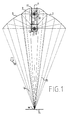
- the reflector 1 consists of two concave mirrors 2 which are firmly connected to one another, 3, as a partial ellipsoid, which is axially symmetrical and with the same direction along an optical axis 4
- Light exit direction are arranged according to arrow 10.
- the reflector is called Blank preferably made by pressing from aluminum sheet, its for reflection intended surface receives a faceting (individual segments).
- the one intended for reflection Surface is - for the purpose of applying heat radiation over the rear part of the reflector - provided with an interference filter layer.
- the lamp 5 serving as back-up lighting while in focus 8 of the lower annular concave mirror 3 lamp 7 is positioned.
- Lamp 7 is used as the main lamp, whereby any radiation in the upper concave mirror through a between two lamps 5, 7 arranged cover plate 12 in the common, slidable Bracket 11 of both lamps is prevented. Both lamps 5, 7 each have one the optical axis 4 arranged in the exit direction according to arrow 10 concave counter reflector 9, 13 in the form of a partial hollow sphere, whereby direct irradiation - i.e. also Heat radiation - on the lighting field is prevented.
- Both concave mirrors 2 and 3 are designed as partial ellipsoids.
- the course of the rays according to FIG. 1 shows that with both concave mirrors 2, 3 acting as partial ellipsoids each have their second focal point 18 in the center of the illumination field 14, one different depth illumination is possible; only the main beam path is mean Beams 15, 16 are shown schematically from the respective center of the lamps.
- the field size results from the natural expansion of the light sources and the scattering structures used, here preferably by faceting the reflector.
- the size of the lighting field 14 is approximately the same for both reflector systems.
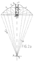
- FIG. 2a It can be seen from FIG. 2a that here - in contrast to FIG. 1 - only the main light provided lamp 7 in focus 8 is in operation, while the other lamp 5 (reserve lamp) is switched off. That about the annular large concave mirror 3 as part of the reflector 1 guided exit radiation 15 is in the second focal point 18 in the plane of the illumination field 14 concentrated, so that there is also good depth illumination of the surgical wound is possible.
- the radiation emerging from lamp 7 frontally in the direction of arrow 10 becomes a concave mirror by the counter reflector 13 designed in the form of a partial hollow sphere 3 reflects, despite a relatively small reflector area, high effectiveness can be achieved.
- a halogen incandescent lamp is preferably used as the lamp 5 used because it is a robust power supply that only depends on the low voltage network in the operating room (24V).
- the switch to a reserve lamp is indicated by an optical signal, see above that the operator or the surgeon is informed that an error is occurring here has and a switch has been made.
- illuminants are preferred Halogen lamps are used, but it is also possible to use discharge lamps or to provide mixed light lighting.
Landscapes
- Engineering & Computer Science (AREA)
- General Engineering & Computer Science (AREA)
- Non-Portable Lighting Devices Or Systems Thereof (AREA)
Abstract
Description
Claims (12)
- Leuchte, insbesondere Operationsleuchte, mit wenigstens zwei elektrischen Lampen, die im Brennpunkt wenigstens eines als Reflektor dienenden Hohlspiegels positionierbar sind, dadurch gekennzeichnet, dass wenigstens zwei Hohlspiegel (2, 3) entlang einer gemeinsamen optischen Achse (4) mit gemeinsamer Lichtaustrittsrichtung angeordnet sind, von denen wenigstens einer als Ring-Reflektor (3) ausgebildet ist, wobei die Hohlspiegel auf der optischen Achse im Abstand zueinander angeordnete Brennpunkte (6, 8) besitzen, in denen jeweils eine Lampe (5, 7) als Leuchtmittel angeordnet ist.
- Leuchte nach Anspruch 1, dadurch gekennzeichnet, dass die Hohlspiegel (2, 3) im wesentlichen axialsymmetrisch ausgebildet sind.
- Leuchte nach Anspruch 1 oder 2, dadurch gekennzeichnet, dass die wenigstens zwei Hohlspiegel (2, 3) einen gemeinsamen Reflektor bilden, wobei wenigstens der als Ringreflektor (3) ausgebildete Hohlspiegel in der der Lichtaustrittsseite entgegengesetzten Richtung mit einem zu ihm konzentrisch angeordneten Hohlspiegel (2) geschlossen ist.
- Leuchte nach Anspruch 2 oder 3, dadurch gekennzeichnet, dass die Fläche wenigstens einer der Hohlspiegel (2, 3) als Teil eines Ellipsoiden ausgebildet ist.
- Leuchte nach einem der Ansprüche 1 bis 4, dadurch gekennzeichnet, dass der Reflektor (1) eine facettierte Oberfläche aufweist.
- Leuchte nach einem der Ansprüche 1 bis 5, dadurch gekennzeichnet, dass der Reflektor (1) mit einer Interferenzschicht zur Abführung von Wärmestrahlung versehen ist.
- Leuchte nach einem der Ansprüche 1 bis 6, dadurch gekennzeichnet, dass eine als Hauptleuchte dienende erste Lampe gegenüber dem Reflektor für eine zweite Lampe als Reserve-Lampe mittels eines Abdeckkörpers (12) abgeschattet ist.
- Leuchte nach Anspruch 7, dadurch gekennzeichnet, dass die Reservelampe als Halogenlampe ausgebildet ist.
- Leuchte nach einem der Ansprüche 1 bis 8, dadurch gekennzeichnet, dass beide Lampen (5, 7) in einer entlang der optischen Achse (4) des Reflektors verschiebbaren Halterung (11) zwecks gleichzeitiger Fokussierung angeordnet sind.
- Leuchte nach einem der Ansprüche 1 bis 9, dadurch gekennzeichnet, dass wenigstens einer der beiden Hohlspiegel (2, 3) des Reflektors 1 mit einem Gegenreflektor (9, 13) versehen ist.
- Leuchte nach einem der Ansprüche 1 bis 10, dadurch gekennzeichnet, das zur Umschaltung auf die Reservelampe eine Umschaltvorrichtung mit einem Strom-Sensor für den Betrieb der als Hauptleuchte dienenden Lampe vorgesehen ist, wobei der Strom-Sensor mit dem Eingang eines steuerbaren Schalters verbunden ist.
- Leuchte nach einem der Ansprüche 1 bis 11, dadurch gekennzeichnet, dass die elektrischen Lampen einzeln und unabhängig voneinander schaltbar sind.
Applications Claiming Priority (2)
| Application Number | Priority Date | Filing Date | Title |
|---|---|---|---|
| DE19956337 | 1999-11-23 | ||
| DE19956337A DE19956337B4 (de) | 1999-11-23 | 1999-11-23 | Leuchte, insbesondere Operationsleuchte, mit wenigstens zwei elektrischen Lampen |
Publications (2)
| Publication Number | Publication Date |
|---|---|
| EP1103761A2 true EP1103761A2 (de) | 2001-05-30 |
| EP1103761A3 EP1103761A3 (de) | 2003-05-02 |
Family
ID=7930045
Family Applications (1)
| Application Number | Title | Priority Date | Filing Date |
|---|---|---|---|
| EP00123843A Withdrawn EP1103761A3 (de) | 1999-11-23 | 2000-11-02 | Leuchte, inbesondere Operationsleuchte, mit wenigstens zwei Lampen |
Country Status (4)
| Country | Link |
|---|---|
| US (1) | US6572234B1 (de) |
| EP (1) | EP1103761A3 (de) |
| JP (1) | JP2001189102A (de) |
| DE (1) | DE19956337B4 (de) |
Families Citing this family (14)
| Publication number | Priority date | Publication date | Assignee | Title |
|---|---|---|---|---|
| US7160002B2 (en) * | 2002-06-20 | 2007-01-09 | Simon Jerome H | Segmented reflector systems and combined reflector and refractor systems |
| WO2005008329A1 (ja) * | 2003-07-16 | 2005-01-27 | Matsushita Electric Industrial Co., Ltd. | 光源装置、照明装置、および投写型表示装置 |
| US7597453B2 (en) * | 2004-01-14 | 2009-10-06 | Simon Jerome H | Luminaires using multiple quasi-point sources for unified radially distributed illumination |
| US7677760B2 (en) * | 2004-01-14 | 2010-03-16 | Simon Jerome H | Efficient and uniformly distributed illumination from multiple source luminaires |
| US7258467B2 (en) * | 2004-03-12 | 2007-08-21 | Honeywell International, Inc. | Low profile direct/indirect luminaires |
| US7121684B2 (en) * | 2004-06-10 | 2006-10-17 | Genlyte Thomas Group, Llc | Garage light luminaire with circular compact fluorescent emergency lighting optics |
| DE102004055838B4 (de) * | 2004-11-19 | 2011-07-28 | Dräger Medical GmbH, 23558 | Operationsleuchte und Ansteuerungsvorrichtung |
| DE102004055839B4 (de) * | 2004-11-19 | 2011-06-16 | Dräger Medical GmbH | Operationsleuchte |
| EP1847762B1 (de) * | 2006-04-19 | 2009-07-08 | FARO FABBRICA APPARECCHIATURE RAZIONALI ODONTOIATRICHE S.p.A. | Kompakte Beleuchtungsvorrichtung, insbesondere anwendbar bei einer zahnärztlichen Lampe |
| TW201017051A (en) * | 2008-10-17 | 2010-05-01 | Ind Tech Res Inst | Illumination system |
| DE102013220218A1 (de) * | 2013-10-07 | 2015-04-09 | Osram Gmbh | Leuchte mit TIR-Reflektor |
| WO2015149061A2 (en) * | 2014-03-28 | 2015-10-01 | Hubbell Incorporated | Optical shield for narrow beam distribution in led fixtures |
| JP6484981B2 (ja) * | 2014-09-30 | 2019-03-20 | 日亜化学工業株式会社 | 照明装置及び灯具 |
| ES2926223T3 (es) * | 2017-03-15 | 2022-10-24 | Nanjing Mindray Bio Medical Electronics Co Ltd | Dispositivo emisor de luz y lámpara quirúrgica |
Citations (1)
| Publication number | Priority date | Publication date | Assignee | Title |
|---|---|---|---|---|
| DE9311156U1 (de) | 1993-07-20 | 1993-10-14 | Karl Leibinger Medizintechnik GmbH & Co. KG, 78570 Mühlheim | Einrichtung zum wechselseitigen Positionieren von wenigstens zwei Lampen |
Family Cites Families (6)
| Publication number | Priority date | Publication date | Assignee | Title |
|---|---|---|---|---|
| US2088024A (en) * | 1935-09-11 | 1937-07-27 | Baber Emil | Operating room lamp |
| US4451873A (en) * | 1980-03-10 | 1984-05-29 | General Motors Corporation | Reflector for a sealed beam lamp |
| US4587601A (en) * | 1981-07-23 | 1986-05-06 | Collins Dynamics, Inc. | Combined flood and spot light incorporating a reflector member of circular and parabolic longitudinal cross section |
| US4755916A (en) * | 1981-07-23 | 1988-07-05 | Collins Dynamics | Combined flood and spot light |
| US5951139A (en) * | 1997-04-17 | 1999-09-14 | Steris Corporation | Surgical light with reflector-lamps and flat reflector panels |
| JP3983847B2 (ja) * | 1997-04-30 | 2007-09-26 | 浜松ホトニクス株式会社 | ミラー付きフラッシュランプ |
-
1999
- 1999-11-23 DE DE19956337A patent/DE19956337B4/de not_active Expired - Fee Related
-
2000
- 2000-10-03 US US09/678,005 patent/US6572234B1/en not_active Expired - Fee Related
- 2000-11-02 EP EP00123843A patent/EP1103761A3/de not_active Withdrawn
- 2000-11-22 JP JP2000356136A patent/JP2001189102A/ja active Pending
Patent Citations (1)
| Publication number | Priority date | Publication date | Assignee | Title |
|---|---|---|---|---|
| DE9311156U1 (de) | 1993-07-20 | 1993-10-14 | Karl Leibinger Medizintechnik GmbH & Co. KG, 78570 Mühlheim | Einrichtung zum wechselseitigen Positionieren von wenigstens zwei Lampen |
Also Published As
| Publication number | Publication date |
|---|---|
| EP1103761A3 (de) | 2003-05-02 |
| DE19956337B4 (de) | 2004-11-25 |
| DE19956337A1 (de) | 2001-06-07 |
| JP2001189102A (ja) | 2001-07-10 |
| US6572234B1 (en) | 2003-06-03 |
Similar Documents
| Publication | Publication Date | Title |
|---|---|---|
| DE19956337B4 (de) | Leuchte, insbesondere Operationsleuchte, mit wenigstens zwei elektrischen Lampen | |
| EP2207994B1 (de) | LED-Operationsraum-Leuchte | |
| DE10218310A1 (de) | Fahrzeugscheinwerfer | |
| DE19853402B4 (de) | Scheinwerfer mit hyperbolischem Reflektor und Scheinwerfereinsatz mit einem solchen Scheinwerfer | |
| DE102004055839B4 (de) | Operationsleuchte | |
| DE102017204517A1 (de) | Optisches Projektionssystem und Projektionsscheinwerfer zur Bildung eines zweifachen Lichtwegs und Fahrzeug, in dem dieses optische System eingesetzt wrid | |
| EP0982534A2 (de) | Leuchte zur Bildung eines schattenarmen Beleuchtungsfeldes | |
| DE19942671A1 (de) | Fahrzeugscheinwerfer mit Niveaureguliereinheit | |
| DE68919227T2 (de) | Scheinwerfer für fahrzeuge. | |
| DE102004055838B4 (de) | Operationsleuchte und Ansteuerungsvorrichtung | |
| DE69312213T2 (de) | Scheinwerfer für Fahrzeuge | |
| EP1431158B1 (de) | Signal- und Fahrlichtscheinwerfer für Schienenfahrzeuge | |
| EP0402845B1 (de) | Scheinwerfer, der in seiner Helligkeit stufenlos regelbar ist | |
| DE2056996C3 (de) | Beleuchtungseinrichtung für Kraftfahrzeuge | |
| EP0401711B1 (de) | Lampenanordnung, insbesondere für eine Signaleinrichtung | |
| EP2092233B1 (de) | Operations- oder untersuchungsleuchte | |
| EP1282151A2 (de) | Entladungslampe und Scheinwerfer für ein Kraftfahrzeug | |
| EP0974786B1 (de) | Scheinwerferanordnung nach dem Projektionstyp für ein Kraftfahrzeug | |
| EP1176358A2 (de) | Beleuchtungssystem und -verfahren sowie Fahrzeug mit einem Beleuchtungssystem | |
| DE10151978A1 (de) | Operationsleuchte | |
| DE839974C (de) | Elektrische Gluehlampe fuer Fahrzeugscheinwerfer | |
| EP0560216B1 (de) | Brennpunktverstellung eines Leuchtmittels in einem Gehäuse | |
| EP0347700B1 (de) | Leuchte | |
| DE19825375C2 (de) | Auf- und abblendbarer Scheinwerfer mit Gasentladungslampe, insbesondere für Kraftfahrzeuge | |
| DE69933419T2 (de) | Dimmbare Beleuchtungseinrichtung mit einer Entladungslampe |
Legal Events
| Date | Code | Title | Description |
|---|---|---|---|
| PUAI | Public reference made under article 153(3) epc to a published international application that has entered the european phase |
Free format text: ORIGINAL CODE: 0009012 |
|
| 17P | Request for examination filed |
Effective date: 20001113 |
|
| AK | Designated contracting states |
Kind code of ref document: A2 Designated state(s): AT BE CH CY DE DK ES FI FR GB GR IE IT LI LU MC NL PT SE TR |
|
| AX | Request for extension of the european patent |
Free format text: AL;LT;LV;MK;RO;SI |
|
| PUAL | Search report despatched |
Free format text: ORIGINAL CODE: 0009013 |
|
| AK | Designated contracting states |
Designated state(s): AT BE CH CY DE DK ES FI FR GB GR IE IT LI LU MC NL PT SE TR |
|
| AX | Request for extension of the european patent |
Extension state: AL LT LV MK RO SI |
|
| RIC1 | Information provided on ipc code assigned before grant |
Ipc: 7F 21W 131:205 Z Ipc: 7F 21W 131/205 B Ipc: 7F 21S 8/00 B Ipc: 7F 21V 7/09 B Ipc: 7F 21V 7/00 B Ipc: 7F 21V 19/04 A |
|
| AKX | Designation fees paid |
Designated state(s): DE FR GB IT |
|
| STAA | Information on the status of an ep patent application or granted ep patent |
Free format text: STATUS: THE APPLICATION IS DEEMED TO BE WITHDRAWN |
|
| 18D | Application deemed to be withdrawn |
Effective date: 20060110 |