EP1103773B1 - Trockenrähmchen für keramische Formlinge - Google Patents
Trockenrähmchen für keramische Formlinge Download PDFInfo
- Publication number
- EP1103773B1 EP1103773B1 EP00122197A EP00122197A EP1103773B1 EP 1103773 B1 EP1103773 B1 EP 1103773B1 EP 00122197 A EP00122197 A EP 00122197A EP 00122197 A EP00122197 A EP 00122197A EP 1103773 B1 EP1103773 B1 EP 1103773B1
- Authority
- EP
- European Patent Office
- Prior art keywords
- cited
- drying frame
- plate
- supporting
- perforations
- Prior art date
- Legal status (The legal status is an assumption and is not a legal conclusion. Google has not performed a legal analysis and makes no representation as to the accuracy of the status listed.)
- Expired - Lifetime
Links
- 238000001035 drying Methods 0.000 title claims description 24
- 239000000919 ceramic Substances 0.000 title claims description 6
- 239000002184 metal Substances 0.000 claims description 11
- 229910052751 metal Inorganic materials 0.000 claims description 11
- 239000004033 plastic Substances 0.000 claims description 10
- 229920003023 plastic Polymers 0.000 claims description 10
- 239000011152 fibreglass Substances 0.000 claims description 3
- 239000000463 material Substances 0.000 claims description 3
- 230000002787 reinforcement Effects 0.000 claims description 3
- 238000002347 injection Methods 0.000 claims description 2
- 239000007924 injection Substances 0.000 claims description 2
- 238000000465 moulding Methods 0.000 description 13
- 239000011449 brick Substances 0.000 description 12
- 238000004519 manufacturing process Methods 0.000 description 10
- 238000013461 design Methods 0.000 description 4
- 210000002414 leg Anatomy 0.000 description 4
- 238000011161 development Methods 0.000 description 3
- 230000018109 developmental process Effects 0.000 description 3
- 238000012986 modification Methods 0.000 description 3
- 230000004048 modification Effects 0.000 description 3
- 238000012360 testing method Methods 0.000 description 3
- 238000010276 construction Methods 0.000 description 2
- 238000005260 corrosion Methods 0.000 description 2
- 230000007797 corrosion Effects 0.000 description 2
- 238000004049 embossing Methods 0.000 description 2
- 238000010304 firing Methods 0.000 description 2
- 238000004080 punching Methods 0.000 description 2
- 235000001674 Agaricus brunnescens Nutrition 0.000 description 1
- 229910000639 Spring steel Inorganic materials 0.000 description 1
- 229910000831 Steel Inorganic materials 0.000 description 1
- HCHKCACWOHOZIP-UHFFFAOYSA-N Zinc Chemical compound [Zn] HCHKCACWOHOZIP-UHFFFAOYSA-N 0.000 description 1
- 230000006978 adaptation Effects 0.000 description 1
- 238000004026 adhesive bonding Methods 0.000 description 1
- 230000002411 adverse Effects 0.000 description 1
- 238000005452 bending Methods 0.000 description 1
- 239000003365 glass fiber Substances 0.000 description 1
- 239000007788 liquid Substances 0.000 description 1
- 229910001092 metal group alloy Inorganic materials 0.000 description 1
- 238000000034 method Methods 0.000 description 1
- 229920000642 polymer Polymers 0.000 description 1
- 239000011819 refractory material Substances 0.000 description 1
- 238000010079 rubber tapping Methods 0.000 description 1
- 238000005070 sampling Methods 0.000 description 1
- 239000007779 soft material Substances 0.000 description 1
- 238000003892 spreading Methods 0.000 description 1
- 229910001220 stainless steel Inorganic materials 0.000 description 1
- 239000010959 steel Substances 0.000 description 1
- 238000003860 storage Methods 0.000 description 1
- 238000012549 training Methods 0.000 description 1
- 210000000689 upper leg Anatomy 0.000 description 1
- 238000009423 ventilation Methods 0.000 description 1
- 239000011701 zinc Substances 0.000 description 1
- 229910052725 zinc Inorganic materials 0.000 description 1
Images


Classifications
-
- F—MECHANICAL ENGINEERING; LIGHTING; HEATING; WEAPONS; BLASTING
- F26—DRYING
- F26B—DRYING SOLID MATERIALS OR OBJECTS BY REMOVING LIQUID THEREFROM
- F26B25/00—Details of general application not covered by group F26B21/00 or F26B23/00
- F26B25/06—Chambers, containers, or receptacles
- F26B25/14—Chambers, containers, receptacles of simple construction
- F26B25/18—Chambers, containers, receptacles of simple construction mainly open, e.g. dish, tray, pan, rack
-
- B—PERFORMING OPERATIONS; TRANSPORTING
- B28—WORKING CEMENT, CLAY, OR STONE
- B28B—SHAPING CLAY OR OTHER CERAMIC COMPOSITIONS; SHAPING SLAG; SHAPING MIXTURES CONTAINING CEMENTITIOUS MATERIAL, e.g. PLASTER
- B28B11/00—Apparatus or processes for treating or working the shaped or preshaped articles
- B28B11/24—Apparatus or processes for treating or working the shaped or preshaped articles for curing, setting or hardening
- B28B11/248—Supports for drying
Definitions
- the invention relates to dry frames for ceramic moldings, in particular Roof tiles, with at least one molding receiving and at least partially perforated plate-shaped base and applied to this the molding in different levels supporting abutments.
- drying frames are disclosed whose support areas are formed by a plurality of separately height-adjustable support points, which by an automatic device in each case for the just to be produced Tile model are adjustable.
- the effort, all segments height adjustable leads to unacceptably high costs, and because of The large number of moving parts, the dry frames are very susceptible to interference and therefore not suitable for harsh operation in a brickyard.
- the accessory tiles are with DE-GM 89 00 937 and DE-GM 86 19 258th Similar adjustability proposed, which also require a lot of effort.
- DE-AS 26 25 480 discloses dry frame for roof tiles whose base frame one or more parts made of plastic, with longitudinal webs, in particular the outer webs, can be used as bearing surfaces and with recesses and / or surveys are equipped to accommodate the attachable elements assets that form the actual bearing surfaces.
- These elements can be cylindrical with carrying deck surface be it
- larger, specially designed structures proposed, for example from the cylindrical pins or more complicated elevations or breakthroughs are recorded.
- These structures can, for example by gluing, be fixed; if they are just plugged in, they are also interchangeable and allow subsequent modifications of the support geometry of the Dry box using stocked parts.
- As these, however is fastened only on the struts is neither a universal construction option given, nor any support levels can be set because the mounting option yes only on the designated as bearing surfaces surfaces of the Striving are given.
- the invention is therefore based on the task ofngerrähmchen designated To create genus, with a simple structure and subsequently to different Tile models are adaptable, and with the lowest possible coverage the bottom of the brick optimum drying while good Ensuring ventilation, and providing a fast, inexpensive setting for Allow drying tests and with low tooling costs and by Using standard components exceptionally short design, manufacturing, and thus allow delivery times, and furthermore also at low Quantities prove to be inexpensive and the corresponding to the rough Operation of a brickyard are robust and high process safety Offer.
- FIG. 1 shows a dry material carrier. From longitudinal profiles 1 and cross sections 2, a profile frame 3 is formed, mounted on the four dry frames 4 are. Thesenrähmchen 4 each consist of a formed of sheet metal Board 5, the side and longitudinal strips 6, 7 to increase the stability folded downwards or upwards. The board 5 is only in the first one Board and only partially shown, provided in close pitch with holes 8. These perforations advantageously extend over the entire board, but at least over the intended for the molding bearing surfaces.
- support body 9 In selected of these holes support body 9 are inserted, above the Board have a shaft 10, the free end in a flange-like spreading Head 11 end. Due to different length of the shafts are different Pad levels on the heads 11 created.
- FIG. 3 a section of a circuit board 5 is shown enlarged in its perforation 8 a support body 9 is inserted.
- This support body has at the free end of his Shank 10 on the flange-like projecting head 11, the upper deck surface 13 is formed mushroom or spherical shell-like. This vault makes it easier Sliding the moldings, and on the other hand, the head 11 does not cover with its entire Base area of the molding 12 and thus facilitates the drying process.
- the length of the shank 10 from the upper deck surface 13 to the flange 14 is determined the edition level, and the locking body 15 secures the grip.
- the different support levels are determined by the distance of the flange 14th determined to the top surface 13, and when changing the support height in adaptation to other brick models can be taken from the support body, and at the same Place, or, on request, anywhere else can be Insert support body with optionally changed shaft length, so another To get support image.
- the invention is not limited solely to the illustrated embodiment.
- the shaft of the support body 9 with a in a groove thereof inserted it be fitted form-locking spring.
- the Holes can also be embossed knob-like elevations on the corresponding molded support body are attachable.
- Dry frames are also used as firing frames, so can both the boards and the support body made of refractory materials (preferably Ceramic), and the ceramic plate is useful in such case with correspondingly deep, bush-like recesses for receiving the Shafts provided the support body.
- refractory materials preferably Ceramic
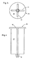
- FIG. 4 and 5 is a created as a plastic injection body support body easy and inexpensive to build.
- Made of a correspondingly heat-resistant Plastic is made of glass fiber using a reinforcement, for example a support body 16 created, the shaft by four wide longitudinal ribs 17 rigid is designed. He gets to the top of a head plate receiving the molding 18 supported, which is carried out essentially flat, and in each case only the upper edge is slightly rounded.
- the reinforcement with fiberglass or the like gives improved dimensional stability, and, as already executed, which prevent substantially the shaft forming longitudinal ribs lateral bending under the influence of the weight taken up.
- a latching body 19 is provided, which has a perforation. 8 the board 5 passes through and its edge area is able to reach behind.
- sheets of a light metal alloy or stainless steels can also be used be like steel sheets, especially if they are made by a plastic or Zinc deposit are protected against corrosion.
- FIG. 6 is a side view, FIG. 7 a front view and FIG Top view of a support body 20 shown, the top plate 21 is a part of a Able to take moldings.
- Figures 7 and 8 show are free edge strips slightly folded in the top plate 21.
- Those shown in Figures 6 and 7 Legs 22 are not completely around against the top plate 21 in the free state 90 ° beveled.
- the lower base of these legs 22 settles as StützfJowne 23 on a board 5, not shown, and the beveled from them Grippers 24 each penetrate a perforation of such a board and engage behind when springing back the edge area of this perforation.
- the top plate 21 is square with a side length of 30 mm, and the legs are designed such that for the distance of the support surfaces 23 to the upper surface of the Headstock 21 heights from 10 to 50 mm in 0.5 mm increments. So can with seventy-nine supporting bodies 20 of the structure are made, the Production of the support body is facilitated by that in principle the same Tool is usable.
- the perforation of the board is appropriate here executed that it is formed by rectangular perforations 5 x 6 mm or through perforations that are correspondingly larger.
- the thighs are functional in this case of the base so folded that in the manufacturing state angle be reached, which exceed 90 °, and the angles shown in the figures of 90 ° only after the spring back when inserting into the board achieved.
Landscapes
- Engineering & Computer Science (AREA)
- Mechanical Engineering (AREA)
- Structural Engineering (AREA)
- Chemical & Material Sciences (AREA)
- Ceramic Engineering (AREA)
- General Engineering & Computer Science (AREA)
- Furnace Charging Or Discharging (AREA)
- Drying Of Solid Materials (AREA)
- Devices For Post-Treatments, Processing, Supply, Discharge, And Other Processes (AREA)
- Moulds, Cores, Or Mandrels (AREA)
- Compositions Of Oxide Ceramics (AREA)
Description
- Figur 1
- eine schematisch-perspektivische Ansicht eines Profilrahmens mit mehreren aufgesetzten Trockenrähmchen,
- Figur 2
- einen einem Trockenrähmchen entsprechenden Ausschnitt des Profilrahmens nach Figur 1 mit aufgelegtem Formling in der Seitenansicht,
- Figur 3
- einen Längsschnitt durch einen in die Basis eines Trockenrähmchens eingesteckten Stützkörper,
- Figuren 4 und 5
- eine Seitenansicht sowie eine Unteransicht eines aus glasfaserverstärktem Kunststoff erstellten Stützkörpers, und
- Figuren 6 bis 8
- in Frontal-, Seiten- sowie Draufsicht einen aus korrosionsbeständigem Feder-Stahlblech erstellten Stützkörper.
- 1
- Längsprofile
- 2
- Querprofile
- 3
- Profilrahmen
- 4
- Trockenrähmchen
- 5
- Platine
- 6
- Seitenstreifen
- 7
- Längsstreifen
- 8
- Lochung
- 9
- Stützkörper
- 10
- Schaft
- 11
- Kopf
- 12
- Formling
- 13
- Deckfläche
- 14
- Flansch
- 15
- Rastkörper
- 16
- Stützkörper
- 17
- Längsrippen
- 18
- Kopfplatte
- 19
- Rastkörper
- 20
- Stützkörper
- 21
- Kopfplatte
- 22
- Schenkel
- 23
- Stützfläche
- 24
- Greifer
Claims (13)
- Trockenrähmchen (4) für keramische Formlinge (12), insbesondere Dachziegel, mit einer zumindest einen Formling (12) aufnehmenden und zumindest bereichsweise perforierten plattenförmigen Basis sowie auf diese aufgebrachte, den Formling in unterschiedlichen Niveaus abstützenden Aufbauten,
dadurch gekennzeichnet, daß der den Formling (12) aufnehmende Bereich der Basis in enger Teilung mit Lochungen (8) ausgestattet ist, und dass in ausgewählte dieser Lochungen (8) vorzugsweise fixiert und entnehmbar gehaltene Schäfte (10) von Stützkörpem (9) eingesteckt sind, deren freie Enden Formlinge (12) abzustützen vermögen. - Trockenrähmchen nach Anspruch 1,
dadurch gekennzeichnet, daß die Basis eine aus Metallblech bestehende Platine (5) aufweist, deren sie begrenzenden Quer- und Längsstreifen (6, 7) abgekantet sind. - Trockenrähmchen nach Anspruch 1,
dadurch gekennzeichnet, daß die Platine (5) aus hitzebeständigem Kunststoff besteht. - Trockenrähmchen nach Anspruch 1,
dadurch gekennzeichnet, daß die Platine (5) sowie die Stützkörper (9) aus feuerfestem Werkstoff, insbesondere Keramik, bestehen. - Trockenrähmchen nach mindestens einem der Ansprüche 1 bis 4, gekennzeichnet durch tiefe, den Endbereich von Schäften (10) aufnehmende Lochungen (8) in der Platine (5) oder auf die Platine (5) aufgebrachte Hülsen.
- Trockenrähmchen nach mindestens einem der Ansprüche 1 bis 3,
dadurch gekennzeichnet, daß Kunststoff- oder Blechplatinen (5) noppenartige Erhebungen aufweisen, auf die Stützkörper mit entsprechend ausgebildeten unteren Schaftenden aufsteckbar sind. - Trockenrähmchen nach mindestens einem der Ansprüche 1 bis 4,
dadurch gekennzeichnet, daß die unteren Schaftenden von Stützkörpern einen sich auf Randbereiche von Lochungen (8) der Platine (5) abstützenden Flansch (14) aufweisen, an den sich ein die Lochung (8) durch- und dessen Randbereich hintergreifender Rastkörper (15) anschließt. - Trockenrähmchen nach mindestens einem der Ansprüche 1 bis 7,
dadurch gekennzeichnet, daß Stützkörper (16) als Spritzgußteil aus warmformbeständigem Kunststoff erstellt sind. - Trockenrähmchen nach Anspruch 8,
gekennzeichnet durch
eine Bewehrung des Kunststoffes des Stützkörpers (16) durch Glasfaser oder dergleichen. - Trockenrahmen nach Anspruch 8 oder 9,
gekennzeichnet durch
vom Schaft des Stützkörpers (16) ausgehenden oder in bildenden Längsrippen (17). - Trockenrähmchen nach mindestens einem der Ansprüche 1 bis 3,
dadurch gekennzeichnet, daß Stützkörper (9) aus Metall, insbesondere als Schmiedeteil, Preßteil oder Druckgießteil gebildet sind. - Trockenrähmchen nach mindestens einem der Ansprüche 1 bis 3,
gekennzeichnet durch
aus Metallblech gefertigte Stützkörper (20), bei denen von einer als Joch ausgebildeten Kopfplatte (21) zwei die Höhe des Stützkörpers (20) bestimmende, sich auf eine Platine (5) abstützende Schenkel (22) abgebogen sind, die Lochungen einer Platine (5) durch- und hinterfassende Greifer (24) aufweisen und so abgekantet sind, daß sie sich unter Federspannung halten. - Trockenrähmchen nach mindestens einem der Ansprüche 1 bis 12,
dadurch gekennzeichnet, daß Stützkörper (9, 16, 20) mit in Schritten gesteigerter Höhe vorgesehen sind.
Applications Claiming Priority (2)
| Application Number | Priority Date | Filing Date | Title |
|---|---|---|---|
| DE19957352A DE19957352C1 (de) | 1999-11-29 | 1999-11-29 | Trockenrähmchen für keramische Formlinge |
| DE19957352 | 1999-11-29 |
Publications (2)
| Publication Number | Publication Date |
|---|---|
| EP1103773A1 EP1103773A1 (de) | 2001-05-30 |
| EP1103773B1 true EP1103773B1 (de) | 2005-06-01 |
Family
ID=7930689
Family Applications (1)
| Application Number | Title | Priority Date | Filing Date |
|---|---|---|---|
| EP00122197A Expired - Lifetime EP1103773B1 (de) | 1999-11-29 | 2000-10-13 | Trockenrähmchen für keramische Formlinge |
Country Status (4)
| Country | Link |
|---|---|
| EP (1) | EP1103773B1 (de) |
| AT (1) | ATE297003T1 (de) |
| DE (2) | DE19957352C1 (de) |
| ES (1) | ES2243189T3 (de) |
Families Citing this family (3)
| Publication number | Priority date | Publication date | Assignee | Title |
|---|---|---|---|---|
| ITTV20050090A1 (it) | 2005-06-21 | 2006-12-22 | Luca Toncelli | Procedimento e dispositivo per la fabbricazione di manufatti in lastre in conglomerato di materiale lapideo o litoide. |
| FR2890728B1 (fr) * | 2005-09-14 | 2007-11-02 | Terreal Sa | Dispositif de support pour le sechage de produits en terre crue |
| DE102010016045A1 (de) | 2010-03-19 | 2011-09-22 | Alexander Stark | Brennhilfsmittel |
Family Cites Families (13)
| Publication number | Priority date | Publication date | Assignee | Title |
|---|---|---|---|---|
| DE8229196U1 (de) * | 1983-02-17 | Robert Thomas Metall- und Elektrowerke, 5908 Neunkirchen | Trageinheit zur Aufnahme zu trocknender, keramischer Formteile | |
| DE2625480C3 (de) * | 1976-06-05 | 1979-03-22 | Dynamit Nobel Ag, 5210 Troisdorf | Trockenrahmen für Dachziegel |
| DE7926755U1 (de) * | 1979-09-21 | 1980-04-10 | Fa. Robert Thomas, 5908 Neunkirchen | Rahmen zur aufnahme keramischer formkoerper |
| DE8018533U1 (de) * | 1980-07-10 | 1980-10-30 | Thomas Robert Metall Elektro | Palette zur Aufnahme von keramischen Formkoerpern |
| DE8034595U1 (de) * | 1980-12-24 | 1981-05-27 | Robert Thomas Metall- und Elektrowerke, 5908 Neunkirchen | Trockenrahmen zur aufnahme zu trocknender keramischer teile, insbesondere dach- und firstziegel |
| DE8105583U1 (de) * | 1981-02-27 | 1981-08-20 | Robert Thomas Metall- und Elektrowerke, 5908 Neunkirchen | Trageinheit fuer keramische formteile |
| DE8329213U1 (de) * | 1983-10-10 | 1984-02-09 | Robert Thomas Metall- und Elektrowerke, 5908 Neunkirchen | Trockenrahmen fuer dachziegel |
| DE3516490A1 (de) * | 1985-05-08 | 1986-11-13 | Elektroschmelzwerk Kempten GmbH, 8000 München | Brennhilfsmittel |
| DE8619258U1 (de) * | 1986-07-18 | 1986-09-04 | Robert Thomas Metall- und Elektrowerke, 5908 Neunkirchen | Trockenrahmen für keramische Formlinge |
| DE8900937U1 (de) * | 1989-01-27 | 1989-03-23 | Robert Thomas Metall- und Elektrowerke, 57290 Neunkirchen | Trockenrahmen und Trockenrahmen aufweisende Trageinheiten für Form- und Sonderziegel |
| DE3923564C1 (de) * | 1989-07-17 | 1991-01-17 | Riedhammer Gmbh Und Co Kg, 8500 Nuernberg, De | |
| FR2697905B1 (fr) * | 1992-11-12 | 1994-12-23 | Krieg Zivy Ind | Claie de séchage, notamment pour tuiles. |
| DE19740994C2 (de) * | 1997-09-17 | 2001-10-31 | Meindl Josef Gmbh & Co | Trockenrahmen für sich im plastischen Zustand befindliche Gegenstände, insbesondere für Ziegel |
-
1999
- 1999-11-29 DE DE19957352A patent/DE19957352C1/de not_active Expired - Fee Related
-
2000
- 2000-10-13 AT AT00122197T patent/ATE297003T1/de not_active IP Right Cessation
- 2000-10-13 DE DE50010443T patent/DE50010443D1/de not_active Expired - Lifetime
- 2000-10-13 ES ES00122197T patent/ES2243189T3/es not_active Expired - Lifetime
- 2000-10-13 EP EP00122197A patent/EP1103773B1/de not_active Expired - Lifetime
Also Published As
| Publication number | Publication date |
|---|---|
| EP1103773A1 (de) | 2001-05-30 |
| ES2243189T3 (es) | 2005-12-01 |
| ATE297003T1 (de) | 2005-06-15 |
| DE19957352C1 (de) | 2001-04-05 |
| DE50010443D1 (de) | 2005-07-07 |
Similar Documents
| Publication | Publication Date | Title |
|---|---|---|
| EP0332061B1 (de) | Gerüstboden | |
| EP0416411B1 (de) | Trägerplatte für einen Hohlraumboden | |
| DE2727575A1 (de) | Metallgitterrost sowie verfahren und vorrichtung zu seiner herstellung | |
| DE19957352C1 (de) | Trockenrähmchen für keramische Formlinge | |
| DE69107066T2 (de) | Befestigungsvorrichtung. | |
| EP3936680B1 (de) | Fassaden- oder dachverkleidung mit verkleidungselementen | |
| DE202007018793U1 (de) | Bohlenverbindungselement | |
| DE10155021B4 (de) | Wannenträgeranordnung sowie Verfahren und Bausatz zur Montage einer Wannenform in einem Wannenträger | |
| DE2625480C3 (de) | Trockenrahmen für Dachziegel | |
| DE9308401U1 (de) | Dachbelüftungsziegel | |
| DE19844020A1 (de) | Kulturplatte zum Bewurzeln von Jungpflanzen | |
| AT410646B (de) | Einrichtung zum herstellen von teilen aus beton | |
| DE2840401C2 (de) | Wabendecke | |
| DE8034595U1 (de) | Trockenrahmen zur aufnahme zu trocknender keramischer teile, insbesondere dach- und firstziegel | |
| CH649426A5 (de) | Anordnung fuer die befestigung einer oder mehrerer karten mit gedruckten schaltungen in einem telefonapparat. | |
| EP1103672B1 (de) | Dielenparkett aus Massivholzriemen | |
| DE3210114C2 (de) | ||
| DE8329213U1 (de) | Trockenrahmen fuer dachziegel | |
| DE2910369A1 (de) | Schalbrett | |
| DE2437720A1 (de) | Hilfsgeraet und verfahren zum anbringen von wandplatten, insbesondere fliesen | |
| EP0377440B1 (de) | Spielzeug-Steckbausatz mit Plattenelementen und mit Anbauelementen | |
| DE29801711U1 (de) | Haltevorrichtung | |
| DE19621236A1 (de) | Gerüstbohle | |
| DE202025101741U1 (de) | Tunnelbauwerk | |
| DE2157617B2 (de) | Abstandhalter fur Bewehrungsmatten von Betonbauteilen |
Legal Events
| Date | Code | Title | Description |
|---|---|---|---|
| PUAI | Public reference made under article 153(3) epc to a published international application that has entered the european phase |
Free format text: ORIGINAL CODE: 0009012 |
|
| AK | Designated contracting states |
Kind code of ref document: A1 Designated state(s): AT BE CH CY DE DK ES FI FR GB GR IE IT LI LU MC NL PT SE |
|
| AX | Request for extension of the european patent |
Free format text: AL;LT;LV;MK;RO;SI |
|
| 17P | Request for examination filed |
Effective date: 20011121 |
|
| AKX | Designation fees paid |
Free format text: AT BE CH CY DE DK ES FI FR GB GR IE IT LI LU MC NL PT SE |
|
| 17Q | First examination report despatched |
Effective date: 20031119 |
|
| GRAP | Despatch of communication of intention to grant a patent |
Free format text: ORIGINAL CODE: EPIDOSNIGR1 |
|
| RAP1 | Party data changed (applicant data changed or rights of an application transferred) |
Owner name: ROBERT THOMAS METALL- UND ELEKTROWERKE GMBH & |
|
| GRAS | Grant fee paid |
Free format text: ORIGINAL CODE: EPIDOSNIGR3 |
|
| GRAA | (expected) grant |
Free format text: ORIGINAL CODE: 0009210 |
|
| AK | Designated contracting states |
Kind code of ref document: B1 Designated state(s): AT BE CH CY DE DK ES FI FR GB GR IE IT LI LU MC NL PT SE |
|
| PG25 | Lapsed in a contracting state [announced via postgrant information from national office to epo] |
Ref country code: IT Free format text: LAPSE BECAUSE OF FAILURE TO SUBMIT A TRANSLATION OF THE DESCRIPTION OR TO PAY THE FEE WITHIN THE PRESCRIBED TIME-LIMIT;WARNING: LAPSES OF ITALIAN PATENTS WITH EFFECTIVE DATE BEFORE 2007 MAY HAVE OCCURRED AT ANY TIME BEFORE 2007. THE CORRECT EFFECTIVE DATE MAY BE DIFFERENT FROM THE ONE RECORDED. Effective date: 20050601 Ref country code: FI Free format text: LAPSE BECAUSE OF FAILURE TO SUBMIT A TRANSLATION OF THE DESCRIPTION OR TO PAY THE FEE WITHIN THE PRESCRIBED TIME-LIMIT Effective date: 20050601 Ref country code: IE Free format text: LAPSE BECAUSE OF FAILURE TO SUBMIT A TRANSLATION OF THE DESCRIPTION OR TO PAY THE FEE WITHIN THE PRESCRIBED TIME-LIMIT Effective date: 20050601 Ref country code: GB Free format text: LAPSE BECAUSE OF FAILURE TO SUBMIT A TRANSLATION OF THE DESCRIPTION OR TO PAY THE FEE WITHIN THE PRESCRIBED TIME-LIMIT Effective date: 20050601 |
|
| REG | Reference to a national code |
Ref country code: GB Ref legal event code: FG4D Free format text: NOT ENGLISH |
|
| REG | Reference to a national code |
Ref country code: CH Ref legal event code: EP |
|
| REG | Reference to a national code |
Ref country code: IE Ref legal event code: FG4D Free format text: LANGUAGE OF EP DOCUMENT: GERMAN |
|
| REF | Corresponds to: |
Ref document number: 50010443 Country of ref document: DE Date of ref document: 20050707 Kind code of ref document: P |
|
| PG25 | Lapsed in a contracting state [announced via postgrant information from national office to epo] |
Ref country code: SE Free format text: LAPSE BECAUSE OF FAILURE TO SUBMIT A TRANSLATION OF THE DESCRIPTION OR TO PAY THE FEE WITHIN THE PRESCRIBED TIME-LIMIT Effective date: 20050901 Ref country code: GR Free format text: LAPSE BECAUSE OF FAILURE TO SUBMIT A TRANSLATION OF THE DESCRIPTION OR TO PAY THE FEE WITHIN THE PRESCRIBED TIME-LIMIT Effective date: 20050901 Ref country code: DK Free format text: LAPSE BECAUSE OF FAILURE TO SUBMIT A TRANSLATION OF THE DESCRIPTION OR TO PAY THE FEE WITHIN THE PRESCRIBED TIME-LIMIT Effective date: 20050901 |
|
| PG25 | Lapsed in a contracting state [announced via postgrant information from national office to epo] |
Ref country code: AT Free format text: LAPSE BECAUSE OF NON-PAYMENT OF DUE FEES Effective date: 20051013 Ref country code: CY Free format text: LAPSE BECAUSE OF FAILURE TO SUBMIT A TRANSLATION OF THE DESCRIPTION OR TO PAY THE FEE WITHIN THE PRESCRIBED TIME-LIMIT Effective date: 20051013 |
|
| PG25 | Lapsed in a contracting state [announced via postgrant information from national office to epo] |
Ref country code: BE Free format text: LAPSE BECAUSE OF NON-PAYMENT OF DUE FEES Effective date: 20051031 Ref country code: MC Free format text: LAPSE BECAUSE OF NON-PAYMENT OF DUE FEES Effective date: 20051031 Ref country code: LU Free format text: LAPSE BECAUSE OF NON-PAYMENT OF DUE FEES Effective date: 20051031 Ref country code: LI Free format text: LAPSE BECAUSE OF NON-PAYMENT OF DUE FEES Effective date: 20051031 Ref country code: CH Free format text: LAPSE BECAUSE OF NON-PAYMENT OF DUE FEES Effective date: 20051031 |
|
| PG25 | Lapsed in a contracting state [announced via postgrant information from national office to epo] |
Ref country code: PT Free format text: LAPSE BECAUSE OF FAILURE TO SUBMIT A TRANSLATION OF THE DESCRIPTION OR TO PAY THE FEE WITHIN THE PRESCRIBED TIME-LIMIT Effective date: 20051103 |
|
| REG | Reference to a national code |
Ref country code: ES Ref legal event code: FG2A Ref document number: 2243189 Country of ref document: ES Kind code of ref document: T3 |
|
| GBV | Gb: ep patent (uk) treated as always having been void in accordance with gb section 77(7)/1977 [no translation filed] |
Effective date: 20050601 |
|
| REG | Reference to a national code |
Ref country code: IE Ref legal event code: FD4D |
|
| ET | Fr: translation filed | ||
| PLBE | No opposition filed within time limit |
Free format text: ORIGINAL CODE: 0009261 |
|
| STAA | Information on the status of an ep patent application or granted ep patent |
Free format text: STATUS: NO OPPOSITION FILED WITHIN TIME LIMIT |
|
| 26N | No opposition filed |
Effective date: 20060302 |
|
| REG | Reference to a national code |
Ref country code: CH Ref legal event code: PL |
|
| BERE | Be: lapsed |
Owner name: ROBERT THOMAS METALL- UND ELEKTROWERKE G.M.B.H. & Effective date: 20051031 |
|
| PGFP | Annual fee paid to national office [announced via postgrant information from national office to epo] |
Ref country code: ES Payment date: 20071030 Year of fee payment: 8 |
|
| REG | Reference to a national code |
Ref country code: ES Ref legal event code: FD2A Effective date: 20081014 |
|
| PG25 | Lapsed in a contracting state [announced via postgrant information from national office to epo] |
Ref country code: ES Free format text: LAPSE BECAUSE OF NON-PAYMENT OF DUE FEES Effective date: 20081014 |
|
| PGFP | Annual fee paid to national office [announced via postgrant information from national office to epo] |
Ref country code: DE Payment date: 20121023 Year of fee payment: 13 |
|
| PGFP | Annual fee paid to national office [announced via postgrant information from national office to epo] |
Ref country code: NL Payment date: 20121019 Year of fee payment: 13 |
|
| REG | Reference to a national code |
Ref country code: NL Ref legal event code: V1 Effective date: 20140501 |
|
| REG | Reference to a national code |
Ref country code: DE Ref legal event code: R119 Ref document number: 50010443 Country of ref document: DE Effective date: 20140501 |
|
| PG25 | Lapsed in a contracting state [announced via postgrant information from national office to epo] |
Ref country code: NL Free format text: LAPSE BECAUSE OF NON-PAYMENT OF DUE FEES Effective date: 20140501 Ref country code: DE Free format text: LAPSE BECAUSE OF NON-PAYMENT OF DUE FEES Effective date: 20140501 |
|
| PGFP | Annual fee paid to national office [announced via postgrant information from national office to epo] |
Ref country code: FR Payment date: 20141022 Year of fee payment: 15 |
|
| REG | Reference to a national code |
Ref country code: FR Ref legal event code: ST Effective date: 20160630 |
|
| PG25 | Lapsed in a contracting state [announced via postgrant information from national office to epo] |
Ref country code: FR Free format text: LAPSE BECAUSE OF NON-PAYMENT OF DUE FEES Effective date: 20151102 |