EP1103868A2 - Bürste zum Entfernen von elektrisch geladenen Teilchen von einer Oberfläche - Google Patents
Bürste zum Entfernen von elektrisch geladenen Teilchen von einer Oberfläche Download PDFInfo
- Publication number
- EP1103868A2 EP1103868A2 EP00124928A EP00124928A EP1103868A2 EP 1103868 A2 EP1103868 A2 EP 1103868A2 EP 00124928 A EP00124928 A EP 00124928A EP 00124928 A EP00124928 A EP 00124928A EP 1103868 A2 EP1103868 A2 EP 1103868A2
- Authority
- EP
- European Patent Office
- Prior art keywords
- brush
- belt
- particles
- supporting device
- contact
- Prior art date
- Legal status (The legal status is an assumption and is not a legal conclusion. Google has not performed a legal analysis and makes no representation as to the accuracy of the status listed.)
- Withdrawn
Links
Images



Classifications
-
- G—PHYSICS
- G03—PHOTOGRAPHY; CINEMATOGRAPHY; ANALOGOUS TECHNIQUES USING WAVES OTHER THAN OPTICAL WAVES; ELECTROGRAPHY; HOLOGRAPHY
- G03G—ELECTROGRAPHY; ELECTROPHOTOGRAPHY; MAGNETOGRAPHY
- G03G21/00—Arrangements not provided for by groups G03G13/00 - G03G19/00, e.g. cleaning, elimination of residual charge
- G03G21/0005—Arrangements not provided for by groups G03G13/00 - G03G19/00, e.g. cleaning, elimination of residual charge for removing solid developer or debris from the electrographic recording medium
Definitions
- This invention relates generally to an electrostatographic printer or copier, and more particularly concerns a device for cleaning the backside of a photoreceptor belt used therein.
- a charge retentive surface i.e., photoconductor, photoreceptor or imaging surface
- a charge retentive surface i.e., photoconductor, photoreceptor or imaging surface
- the resulting pattern of charged and discharged areas on that surface form an electrostatic charge pattern (an electrostatic latent image) conforming to the original image.
- electrostatic latent image an electrostatic latent image
- Toner a finely divided, electrostatically attractable powder referred to as "toner” develops the latent image. Toner is held on the image areas by the electrostatic charge on the surface.
- a toner image is produced in conformity with a light image of the original being reproduced.
- the toner image may then be transferred to a substrate (e.g., paper), and the image affixed thereto to form a permanent record of the image to be reproduced. Subsequent to development, excess toner left on the charge retentive surface is cleaned from the surface.
- a substrate e.g., paper
- This process is well known, and useful for light lens copying from an original, and printing applications from electronically generated or stored originals, where a charged surface may be image-wise discharged in a variety of ways. Ion projection devices where a charge is image-wise deposited on a charge retentive substrate operate similarly.
- One type of charge retentive surface typically utilized in the electrostatographic reproduction device is a photoreceptor belt having a base of flexible material.
- the photoreceptor belt is entrained about a plurality of support rollers so as to form a closed loop path.
- the photoreceptor belt is driven about the closed loop path to present particular areas of the photorceptor belt sequentially into association with electrographic process stations to form desired reproductions.
- Adhered to the backside of the photoreceptor belt is a substrate polycarbonate known as anti curl back coating. The purpose of this coating is to balance the stresses within the photoreceptor belt and control edge curling.
- the anti curl back coating begins to wear and flake off in the form of low charged negative particles.
- a build up of anti curl back coating particles occurs on all parts of the module which come in contact with the anti curl back layer.
- toner particles from the development system, the imaging surface cleaner, and toner airborne in the xerographic module are deposited on the back of the belt.
- This buildup of particles on the backside of the photoreceptor belt and drive roller may adversely affect performance of the photoreceptor belt as it is driven about the closed loop path and, ultimately, overall performance of the reproduction apparatus.
- a non-contact development system such as Hybrid Scavengeless Development (HSD)
- HSD Hybrid Scavengeless Development
- the spacing between the developer and the imaging surface is important.
- debris builds up on the developer backer bars, the photoreceptor is lifted off the backer bars, causing the spacing in the development nip to decrease.
- the different development fields produce streaks on copy in the process direction.
- Excessive debris in the ATA reduces the suction pressure in the ATA and creates transfer defects.
- One mechanism includes a stationary pad of a material such as cotton. This pad can easily become saturated with debris, with the period of time required for the pad to become saturated not readily predictable. Saturation of the pad can cause excessive abrasion and scratching of the photoreceptor belt, necessitating frequent inspection and cleaning.
- a cleaner for the backside of a photoreceptor belt or the drive roller is needed that would preserve drive capacity and prevent anti curl back coating contamination to sensitive subsystems.
- U.S. Pat. No. 4,853,741 to Ku utilizes an indexing web of material, such as a fabric of a non-woven blend of polyester and rayon for example.
- the web is periodically indexed by a motor, which is coupled to the mechanism. While this mechanism reduces the necessity for frequent inspection, it may scratch the dielectric support web if it picks up any abrasive particles or debris.
- U.S. Pat. No. 5,655,205 to Ziegelmuller et al. discloses a mechanism for cleaning the backside of an image bearing dielectric support web including a cleaning blade which engages the backside of the dielectric support web at a predetermined angle so as to wipe the backside of the web.
- a catch tray attached to the blade collects debris removed from the backside of the web.
- an apparatus for removing electrostatically charged particles from a surface includes an endless electrically biased conductive flexible belt brush having a substrate from which conductive fibers extend outwardly, rollers about which the belt brush is entrained, and a cleaning device for cleaning collected particles from the brush belt.
- One of the rollers supporting the brush belt is a drive roller which rotates, thereby moving the brush belt and causing clean fibers to contact the surface to be cleaned.
- the supporting device further comprises drive means operatively associated with the supporting device, to continually advance the cylindrical brush to move clean conductive fibers into contact with the surface being cleaned.
- an electrically biased conductive cylindrical brush having a substrate from which conductive fibers extend outwardly, a cylindrical core about which the substrate is entrained, and a cleaning device for cleaning collected particles from the cylindrical brush.
- the cylindrical core supporting the cylindrical brush rotates, thereby causing clean fibers to contact the surface to be cleaned.
- a printing machine of the type having a photoconductive member in the form of an image bearing belt and an apparatus for removing particles which accumulate on the backside of the image bearing belt or the drive roller supporting the image bearing belt.
- the apparatus for removing accumulated particles includes an electrically biased brush belt, which contacts the surface to be cleaned, and which is supported by a plurality of rollers, one of which is a drive roller, and a cleaning device to remove particles collected by the brush belt.
- the drive roller for the brush belt rotates, thereby moving the brush belt to bring clean fibers into contact with the backside of the image bearing belt or the drive roller supporting the image bearing belt.
- FIG. 1 is a schematic illustration of a printing apparatus incorporating the inventive features of the present invention.
- FIG. 2 is an elevational view of the present invention.
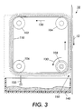
- FIG 3 is an elevational view of another embodiment of the present invention.
- FIG. 4 is an elevational view of still another embodiment of the present invention.
- FIG. 1 depicts schematically the various components thereof
- like reference numerals have been used through out to identify identical elements.
- the brush belt cleaner apparatus of the present invention is particularly well adapted for use in an electrophotographic printing machine, it should become evident from the following discussion that it is equally well suited for use in other applications and is not necessarily limited to the particular embodiment shown herein.
- a reproduction machine in which the present invention finds advantageous use, has a photoreceptor belt 10 , having a photoconductive (or imaging) surface 11 .
- the photoreceptor belt 10 moves in the direction of arrow 12 to advance portions of the belt 10 sequentially through the various processing stations disposed about the path of movement thereof
- the belt 10 is entrained about a stripping roller 14 , a tension roller 16 , a drive roller 20 , and backer bars indicated generally as 15 .
- Drive roller 20 is coupled to a motor 21 by suitable means such as a belt drive.
- the belt 10 is maintained in tension by a pair of springs (not shown) resiliently urging tension roller 16 against the belt 10 with the desired spring force.
- Both stripping roller 14 and tension roller 16 are rotatably mounted. These rollers are idlers, which rotate freely as the belt 10 moves in the direction of arrow 12 .
- a portion of the belt 10 passes through charging station A .
- a corona device 22 charges a portion of the photoreceptor belt 10 to a relatively high, substantially uniform potential, either positive or negative.
- a Raster Output Scanner (ROS) 33 exposes the charged portions of photoreceptor belt 10 to record an electrostatic latent image thereon.
- the belt 10 advances the electrostatic latent image to developing station C .
- a developer housing 34 , 36 , 38 , or 40 is brought into contact with the belt 10 for the purpose of developing the electrostatic latent image.
- Each developer housing 34, 36, 38, and 40 supports a developing system such as magnetic brush rolls 42, 43, 44, and 45, which provides a rotating magnetic member to advance developer mix (i.e. carrier beads and toner) into contact with the electrostatic latent image.
- developer mix i.e. carrier beads and toner
- the electrostatic latent image attracts toner particles from the carrier beads, thereby forming toner powder images on the photoreceptor belt 10 .
- the photoreceptor belt 10 then advances the developed image to transfer station D .
- a sheet of support material such as paper copy sheets is advanced into contact with the developed images on the belt 10 .
- a corona generating device 46 charges the copy sheet to the proper potential so that it becomes tacked to the photoreceptor belt 10 and the toner powder image is attracted from the photoreceptor belt 10 to the sheet.
- Acoustic Transfer Assist device 47 provides vibrational energy to photoreceptor belt 10 at a frequency sufficient to assist in loosening the toner powder image and thereby facilitating transfer of the image to the sheet.
- the corona generator 48 charges the copy sheet to an opposite polarity to de-tack the copy sheet from the belt 10 , whereupon the sheet is stripped from the belt 10 at stripping roller 14 .
- Sheets of support material 49 are advanced to transfer station D from a supply tray 50 . Sheets are fed from tray 50 , with sheet feeder 52 , and advanced to transfer station D along conveyor 56 .
- Fusing station E includes a fuser assembly indicated generally by the reference numeral 70 , which permanently affixes the transfer toner powder images to the sheets.
- the fuser assembly 70 includes a heated fuser roller 72 adapted to be pressure engaged with a backup roller 74 with the toner powder images contacting the fuser roller 72 .
- the toner powder image is permanently affixed to the sheet, and such sheets are directed via a chute 62 to an output 80 or finisher.
- Residual particles remaining on the image side of photoreceptor belt 10 after each copy is made, may be removed at cleaning station F , represented by the reference numeral 92 .
- cleaning station 92 residual toner particles are removed and may also be stored for disposal.
- Residual particles, collecting on the backside of photoreceptor belt 10 may be removed at back of belt cleaning station G .
- the cleaning apparatus of the present invention is represented by the reference numeral 94 , which will be described in greater detail in FIGS. 2-4 . Removed residual particles may also be stored for disposal.
- a machine controller 96 is preferably a known programmable controller or combination of controllers, which conventionally control all of the machine steps and functions described above.
- the controller 96 is responsive to a variety of sensing devices to enhance control of the machine, and also provides connection diagnostic operations to a user interface (not shown) where required.
- a reproduction machine in accordance with the present invention may be any of several well-known devices. Variations may be expected in specific electrophotographic processing, paper handling and control arrangements without effecting the present invention. However, it is believed that the foregoing description is sufficient for purposes of the present application to illustrate the general operation of an electrophotographic printing machine, which exemplifies one type of apparatus employing the present invention therein. Reference is now made to FIGS. 2-4 , where the showings are for the purpose of illustrating preferred embodiments of the present invention and not for limiting the same.
- Wear debris accumulates on the back side of the photoreceptor belt and the drive roller as the result of movement of the photoreceptor belt over the backer bars and rollers supporting the photoreceptor belt. Adhesion of the debris to the back of the belt is low because there is a low triboelectric relationship between the particles and the back of the photoreceptor belt. Therefore, a minimal charge is developed as the particles rub against the backer bars and rollers supporting the photoreceptor belt. Removal of such debris adhered to the back side of a dielectric surface can be accomplished by mechanical, electrical or electro-mechanical means.
- the belt brush cleaner of the present invention employs a combination of electrical and mechanical forces to detach and remove debris from the back side of the photoreceptor belt.
- FIG. 2 shows an elevational view of one embodiment of the present invention.
- the flexible belt brush 110 is shown in operable condition in contact with the backside of photoreceptor belt 10 through cleaning nip 150 .
- Flexible belt brush 110 is electrically biased to suitable magnitude and polarity and is comprised of a continuous loop of conductive backing material (e.g. urethane, polycarbonate or polyester) to which conductive brush fibers are attached with conductive glue in segments, to form a segmented belt brush.
- the flexible belt brush 110 is entrained about four rollers 102 , 104 , 106 and 108 , one of which is a drive roller, and moving in direction 130 opposed to the movement of photoreceptor belt 10 .
- the two rollers 102 and 104 support the belt 110 in brushing contact with photoreceptor belt 10 .
- the third and fourth rollers 106 and 108 support belt 110 as the conductive brush fibers are brought into contact with flicker bars 120 , which engage the fibers of the brush belt as the fibers move past the flicker bars. As the fibers rebound from contact with the flicker bars 120 , the fibers release debris particles, which fall into waste chamber 140 .
- Coupled to the drive roller is a drive means which indexes the belt brush segmentally in direction 180 as the fiber segment contacting the backside of the photoreceptor belt becomes saturated with debris particles.
- an electric potential is applied to the conductive fibers of the brush belt. This potential creates an electric field between the fibers and the ground plane of the photoreceptor.
- the force experienced by the debris particles must exceed the small adhesion force between the debris particles and the backside of the photoreceptor belt in order to detach the particles.
- the electrical force when combined with the mechanical (deflection) forces of the fibers, detaches and removes slightly charged debris particles from the backside of the photoreceptor belt.
- FIG. 3 shows an alternate embodiment of the present invention.
- the flexible belt brush 110 is shown in operable condition in contact with the backside of photoreceptor belt 10 through cleaning nip 150 .
- Flexible belt brush 110 is electrically biased to suitable magnitude and polarity and is comprised of a continuous loop of conductive backing material (e.g. urethane, polycarbonate or polyester) to which conductive brush fibers are attached with conductive glue to form an endless brush belt.
- the flexible belt brush 110 is entrained about four rollers 102 , 104 , 106 and 108 , one of which is a drive roller, and moving in direction 130 opposed to the movement of photoreceptor belt 10 .
- the two rollers 102 and 104 support the belt 110 in brushing contact with photoreceptor belt 10 .
- the third and fourth rollers 106 and 108 support belt 110 as the conductive brush fibers are brought into contact with flicker bar 120 , which engages the fibers of the brush belt as the fibers move past the flicker bar. As the fibers rebound from contact with the flicker bar 120 , the fibers release debris particles, which fall into waste chamber 140 .
- Coupled to the drive roller is a drive means, which continuously rotates the drive roller to move the belt brush in direction 130 .
- FIGS. 2 and 3 may also be configured to remove debris particles accumulating on drive roller 20 , which supports photoreceptor belt 10 , or on other surfaces which contact the backside of photoreceptor belt 10 .
- FIG. 4 illustrates the a third embodiment of the present invention configured to remove debris particles from drive roller 20 , as an example of one such configuration.
- the cylindrical belt brush 110 is in operable contact with drive roller 20 through cleaning nip 160 .
- the cylindrical brush 110 is electrically biased to suitable magnitude and polarity and is comprised of a backing material, to which conductive brush fibers are attached, and a cylindrical core, which may be solid or tubular.
- a drive means which continuously rotates the cylindrical brush 110 .
- the cylindrical brush 110 rotates in direction 130 , opposed to the movement of drive roller 20 , which rotates in direction 170 , and is in brushing contact with drive roller 20 through cleaning nip 160 .
- the conductive brush fibers are brought into contact with flicker bar 120 , which engages the fibers of the cylindrical brush as the fibers move past flicker bar 120 .
- the fibers release debris particles, which fall into waste chamber 140 .
Landscapes
- Physics & Mathematics (AREA)
- General Physics & Mathematics (AREA)
- Cleaning In Electrography (AREA)
- Discharging, Photosensitive Material Shape In Electrophotography (AREA)
- Electrostatic Charge, Transfer And Separation In Electrography (AREA)
Applications Claiming Priority (2)
| Application Number | Priority Date | Filing Date | Title |
|---|---|---|---|
| US09/448,972 US6259882B1 (en) | 1999-11-24 | 1999-11-24 | Cleaning brush for non-imaging surfaces in an electrostatographic printer or copier |
| US448972 | 1999-11-24 |
Publications (2)
| Publication Number | Publication Date |
|---|---|
| EP1103868A2 true EP1103868A2 (de) | 2001-05-30 |
| EP1103868A3 EP1103868A3 (de) | 2003-03-19 |
Family
ID=23782378
Family Applications (1)
| Application Number | Title | Priority Date | Filing Date |
|---|---|---|---|
| EP00124928A Withdrawn EP1103868A3 (de) | 1999-11-24 | 2000-11-15 | Bürste zum Entfernen von elektrisch geladenen Teilchen von einer Oberfläche |
Country Status (3)
| Country | Link |
|---|---|
| US (1) | US6259882B1 (de) |
| EP (1) | EP1103868A3 (de) |
| JP (1) | JP2001175142A (de) |
Families Citing this family (12)
| Publication number | Priority date | Publication date | Assignee | Title |
|---|---|---|---|---|
| US6418285B1 (en) * | 2000-10-27 | 2002-07-09 | Xerox Corporation | BOB cleaners to control and maintain PR module motion quality latitude |
| US6598261B2 (en) * | 2001-09-04 | 2003-07-29 | Paul C. Howard | Printing process web cleaner |
| JP4463504B2 (ja) * | 2002-07-29 | 2010-05-19 | 株式会社リコー | 画像形成装置および複写機 |
| US7366780B2 (en) * | 2002-12-31 | 2008-04-29 | Motorola, Inc. | System and method for controlling and managing sessions between endpoints in a communications system |
| US7162177B2 (en) * | 2003-09-26 | 2007-01-09 | Xerox Corporation | Back of the belt cleaner in an imaging system |
| DE20321046U1 (de) | 2003-10-08 | 2005-12-22 | Bennett, Les, Bingley | Druckbahnreiniger |
| US20050251936A1 (en) * | 2004-05-14 | 2005-11-17 | International Business Machines Corporation | Apparatus and method for cleaning electronic articles |
| US20060228486A1 (en) * | 2005-03-29 | 2006-10-12 | Xerox Corporation | Fabrication and method for making AC biased conductive brush for eliminating VOC induced LCM |
| JP4201033B2 (ja) * | 2006-07-31 | 2008-12-24 | ブラザー工業株式会社 | インクジェット記録装置 |
| US8953968B2 (en) * | 2013-06-11 | 2015-02-10 | Xerox Corporation | Air-bearing photoreceptor backer bar for eliminating transfer streaks |
| CN110788098B (zh) * | 2019-11-07 | 2021-06-11 | 杨宁 | 一种垃圾桶清洗装置 |
| JP7543804B2 (ja) * | 2020-09-23 | 2024-09-03 | 富士フイルムビジネスイノベーション株式会社 | 画像形成装置 |
Family Cites Families (11)
| Publication number | Priority date | Publication date | Assignee | Title |
|---|---|---|---|---|
| US4457615A (en) * | 1982-11-01 | 1984-07-03 | Xerox Corporation | Combined charge/cleaning brush for use in a xerographic copier |
| JPS60144781A (ja) * | 1984-01-09 | 1985-07-31 | Matsushita Electric Ind Co Ltd | 感光体走行装置 |
| US4853741A (en) | 1988-02-23 | 1989-08-01 | Eastman Kodak Company | Disposable web cleaning device for electrostatographic apparatus |
| JPH03266878A (ja) * | 1990-03-16 | 1991-11-27 | Hitachi Koki Co Ltd | 静電式クリーニング装置 |
| JPH064009A (ja) * | 1992-06-22 | 1994-01-14 | Fuji Xerox Co Ltd | 画像形成装置 |
| JPH06161335A (ja) * | 1992-07-03 | 1994-06-07 | Fuji Xerox Co Ltd | 電子写真複写機等の画像形成装置 |
| US5797078A (en) * | 1993-07-09 | 1998-08-18 | Xerox Corporation | Photoreceptor comet prevention brush |
| JPH07271242A (ja) * | 1994-03-28 | 1995-10-20 | Ricoh Co Ltd | 感光体ベルト走行装置 |
| US5655205A (en) | 1995-06-07 | 1997-08-05 | Eastman Kodak Company | Mechanism for cleaning the back side of a web in an electrostatographic reproduction apparatus |
| US5784674A (en) * | 1995-06-29 | 1998-07-21 | Fuji Xerox Co., Ltd. | Inner face cleaning member for an intermediate transfer device |
| US6016415A (en) * | 1998-11-25 | 2000-01-18 | Eastman Kodak Company | Image transfer apparatus and method using a seamed endless belt |
-
1999
- 1999-11-24 US US09/448,972 patent/US6259882B1/en not_active Expired - Fee Related
-
2000
- 2000-11-15 EP EP00124928A patent/EP1103868A3/de not_active Withdrawn
- 2000-11-16 JP JP2000349181A patent/JP2001175142A/ja active Pending
Also Published As
| Publication number | Publication date |
|---|---|
| JP2001175142A (ja) | 2001-06-29 |
| US6259882B1 (en) | 2001-07-10 |
| EP1103868A3 (de) | 2003-03-19 |
Similar Documents
| Publication | Publication Date | Title |
|---|---|---|
| EP0366426B1 (de) | Elektrophotographische Vorrichtung mit einer mittels Wechselspannung betriebenen Reinigungseinrichtung | |
| US3781107A (en) | Cleaning apparatus | |
| US4819026A (en) | Cleaning apparatus for a charge retentive surface | |
| EP0472401B1 (de) | Gerät zur Oberflächenreinigung für die elektrophotographische Bilderstellung | |
| EP0588553B1 (de) | Reinigungsgerät | |
| US4494863A (en) | Cleaning apparatus for a charge retentive surface | |
| US4878093A (en) | Dual roll cleaning apparatus for charge retentive surface | |
| US6259882B1 (en) | Cleaning brush for non-imaging surfaces in an electrostatographic printer or copier | |
| US5530537A (en) | Biased foam roll cleaner | |
| JPS62159172A (ja) | ブレ−ド式クリ−ニング装置を備えた複写装置 | |
| US5329344A (en) | Lubrication of a detoning roll | |
| GB2206846A (en) | Copy sheet cleaning apparatus | |
| US6292637B1 (en) | Blade for removing electrically charged particles from the back side of a belt in an electrostatographic apparatus | |
| US6253056B1 (en) | Foam pad for removing electrostatically charged particles from a surface | |
| US5315358A (en) | Flicker bar with an integral air channel | |
| EP1089141B1 (de) | Reinigungsgerät | |
| US5381218A (en) | Conductive cleaning brush belt and detoning thereof | |
| US5450186A (en) | Retractable flexible cleaner brush | |
| EP0620508B1 (de) | Reinigungsvorrichtung | |
| US5341201A (en) | Xerographic brush cleaner detoner | |
| US8953968B2 (en) | Air-bearing photoreceptor backer bar for eliminating transfer streaks | |
| US5210582A (en) | Stretchable cleaner band disturber | |
| US6144834A (en) | Self biasing, extended nip electrostatic cleaner | |
| US6418285B1 (en) | BOB cleaners to control and maintain PR module motion quality latitude | |
| US5241352A (en) | Air detoned cleaner brush |
Legal Events
| Date | Code | Title | Description |
|---|---|---|---|
| PUAI | Public reference made under article 153(3) epc to a published international application that has entered the european phase |
Free format text: ORIGINAL CODE: 0009012 |
|
| AK | Designated contracting states |
Kind code of ref document: A2 Designated state(s): AT BE CH CY DE DK ES FI FR GB GR IE IT LI LU MC NL PT SE TR |
|
| AX | Request for extension of the european patent |
Free format text: AL;LT;LV;MK;RO;SI |
|
| PUAL | Search report despatched |
Free format text: ORIGINAL CODE: 0009013 |
|
| AK | Designated contracting states |
Kind code of ref document: A3 Designated state(s): AT BE CH CY DE DK ES FI FR GB GR IE IT LI LU MC NL PT SE TR Designated state(s): AT BE CH CY DE DK ES FI FR GB GR IE IT LI LU MC NL PT SE TR |
|
| AX | Request for extension of the european patent |
Extension state: AL LT LV MK RO SI |
|
| 17P | Request for examination filed |
Effective date: 20030919 |
|
| AKX | Designation fees paid |
Designated state(s): DE FR GB |
|
| 17Q | First examination report despatched |
Effective date: 20040322 |
|
| STAA | Information on the status of an ep patent application or granted ep patent |
Free format text: STATUS: THE APPLICATION IS DEEMED TO BE WITHDRAWN |
|
| 18D | Application deemed to be withdrawn |
Effective date: 20041208 |