EP1104039A2 - Agencement de piles à combustible, système d'alimentation en gaz et procédé de fonctionnement de l'agencement - Google Patents
Agencement de piles à combustible, système d'alimentation en gaz et procédé de fonctionnement de l'agencement Download PDFInfo
- Publication number
- EP1104039A2 EP1104039A2 EP00121985A EP00121985A EP1104039A2 EP 1104039 A2 EP1104039 A2 EP 1104039A2 EP 00121985 A EP00121985 A EP 00121985A EP 00121985 A EP00121985 A EP 00121985A EP 1104039 A2 EP1104039 A2 EP 1104039A2
- Authority
- EP
- European Patent Office
- Prior art keywords
- exhaust gas
- cathode
- anode
- expansion machine
- catalytic burner
- Prior art date
- Legal status (The legal status is an assumption and is not a legal conclusion. Google has not performed a legal analysis and makes no representation as to the accuracy of the status listed.)
- Withdrawn
Links
Images
Classifications
-
- H—ELECTRICITY
- H01—ELECTRIC ELEMENTS
- H01M—PROCESSES OR MEANS, e.g. BATTERIES, FOR THE DIRECT CONVERSION OF CHEMICAL ENERGY INTO ELECTRICAL ENERGY
- H01M8/00—Fuel cells; Manufacture thereof
- H01M8/04—Auxiliary arrangements, e.g. for control of pressure or for circulation of fluids
- H01M8/04082—Arrangements for control of reactant parameters, e.g. pressure or concentration
- H01M8/04089—Arrangements for control of reactant parameters, e.g. pressure or concentration of gaseous reactants
-
- H—ELECTRICITY
- H01—ELECTRIC ELEMENTS
- H01M—PROCESSES OR MEANS, e.g. BATTERIES, FOR THE DIRECT CONVERSION OF CHEMICAL ENERGY INTO ELECTRICAL ENERGY
- H01M8/00—Fuel cells; Manufacture thereof
- H01M8/06—Combination of fuel cells with means for production of reactants or for treatment of residues
- H01M8/0606—Combination of fuel cells with means for production of reactants or for treatment of residues with means for production of gaseous reactants
- H01M8/0612—Combination of fuel cells with means for production of reactants or for treatment of residues with means for production of gaseous reactants from carbon-containing material
-
- Y—GENERAL TAGGING OF NEW TECHNOLOGICAL DEVELOPMENTS; GENERAL TAGGING OF CROSS-SECTIONAL TECHNOLOGIES SPANNING OVER SEVERAL SECTIONS OF THE IPC; TECHNICAL SUBJECTS COVERED BY FORMER USPC CROSS-REFERENCE ART COLLECTIONS [XRACs] AND DIGESTS
- Y02—TECHNOLOGIES OR APPLICATIONS FOR MITIGATION OR ADAPTATION AGAINST CLIMATE CHANGE
- Y02E—REDUCTION OF GREENHOUSE GAS [GHG] EMISSIONS, RELATED TO ENERGY GENERATION, TRANSMISSION OR DISTRIBUTION
- Y02E60/00—Enabling technologies; Technologies with a potential or indirect contribution to GHG emissions mitigation
- Y02E60/30—Hydrogen technology
- Y02E60/50—Fuel cells
Definitions
- the invention relates to an arrangement with fuel cells and Gas supply system and a method of operating the Arrangement according to the preambles of the independent claims.
- Fuel cell systems require the air supply Kazhode side usually a compaction machine. Either with methanol powered systems as well as with others Fuel operated systems is subject to high system pressure yourself advantageous. For example, the water balance of the system improved. Furthermore, the efficiency of the Fuel cell due to the higher oxygen partial pressure, and the pressure losses in the fuel cell system are minimized.
- a boiler room is one Reforming unit and / or a boiler room in the inflow path the anode arranged evaporator unit in the cathode exhaust gas flow path arranged, as well as an expansion machine in the Cathode exhaust flow path between a catalytic burner and the boiler room.
- the reforming unit preferably has one by one Boiler room heated reforming room to carry out a Reforming reaction, using the boiler room as a heat exchanger is trained.
- Exhaust gas from the fuel cell which by the catalytic burner heated to a high first temperature is, preferably at least cathode exhaust, is in the boiler room cooled to a very low temperature. It is not Catalytic burner necessary to complete a reforming reaction and / or evaporation upstream of the anode support.
- the cathode exhaust gas is preferably in the catalytic burner heated to a first temperature between 450 ° C and 900 ° C and after cooling in an expansion machine by about 50 ° C to 200 ° C then the boiler room of the reforming and / or Evaporator unit fed where the medium in the cathode exhaust flow path by heat exchange to a lower temperature is cooled from preferably below 200 ° C.
- the evaporator unit is preferably a hot gas evaporator educated.
- An exhaust gas turbocharger is advantageous as an expansion machine or to provide a turbo generator. So that the high Exhaust gas temperature downstream of the catalytic burner be exploited.
- the catalytic Burner a metering device of fuel.
- the fuel is added to the catalytic Burner preferably depending on a desired temperature of the medium in the boiler room of the reforming and / or Evaporator unit. It is particularly advantageous here
- the fuel is added to the catalytic burner control, wherein data from a map of a control device are taken, which shows a drop in temperature of the Contains cathode exhaust gas above the expansion machine.
- the cathode exhaust gas flow path upstream of the catalytic burner exhaust fed to the anode as fuel Preferably Anode exhaust and cathode exhaust combined in a mixer and mixed.
- a blow-off valve arranged between expansion machine and reforming and / or evaporator unit. This serves the security of the system, so that Reforming and / or evaporator device not with impermissibly high amounts of energy of the heat exchange medium be charged.
- the compressor is expediently mechanically via a common shaft or electrical with the expansion machine coupled.
- the invention is both for stationary for Fuel cell systems suitable as well as for such Fuel cell systems for the operation of vehicles are determined.
- the invention is particularly advantageous for Fuel cell systems, usually at low Temperatures are operated, such as fuel cell systems with polymer electrolyte membranes, especially those in which Fuels such as methanol can be used. There are high ones Temperatures in the system are usually not available or are not desirable due to the temperature balance.
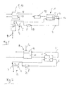
- a fuel cell 1 has an anode 2 and one Cathode 3.
- the fuel cell is simplified as one single cell, but can also be a stack of Represent fuel cells.
- the anode 2 is connected to a via a media inflow path hydrogen-rich reformate from a reforming unit 9 with a reformer 11 and a thermally coupled boiler room 12, which is formed by a catalytic burner, charged with a medium containing hydrogen.
- the exhaust from the Anode 2 is the anode exhaust gas flow path 2 ' Catalytic burner 12 supplied, with the catalytic Burner 12 still an air metering to supply 02 as Fuel is provided.
- From the catalytic burner 12 can the anode exhaust gas in a heat exchanger Water evaporation can be used and / or in the atmosphere to be disposed of.
- the heat generated in the catalytic burner 12 supports the endothermic reforming reaction in the reformer 11.
- a compressor 5 is arranged in a media inflow path for the cathode 3 and compresses an oxygen-containing medium O 2 , preferably air, which is fed to the cathode 3 at high pressure. The reaction between the oxygen and hydrogen-containing media then takes place in the fuel cell.
- a catalytic burner 8 is arranged in the cathode exhaust gas flow path 4 and burns the cathode exhaust gas with further fuel and thus increases the exhaust gas temperature. For this purpose, a fuel is additionally metered into the catalytic burner 8 via a metering device 13.
- the hot cathode exhaust passes through the cathode exhaust flow path 4 into an expansion machine 7.
- Expansion machine 7 is preferably coupled to the compressor 5, particularly preferably mechanically via a common shaft 6.
- Die preferred expansion machine 7 is a turbine and can by the energy recuperated from the hot exhaust gas compresses the compressor 5 drive.
- FIG. 1 is a particularly preferred embodiment of the Arrangement shown schematically. Same Elements are given the same reference numerals as in FIG. 1 designated.
- a hydrogen-rich medium enters a reformer 11 a reforming unit 9 and is via an anode inflow path further into a carbon monoxide removal unit 15 directed, cleaned there and as a hydrogen-rich reformate fed to an anode 2 of a fuel cell 1.
- the Reforming unit 9 has a reformer 11 and one with it thermally coupled boiler room 17.
- the fuel cell 1 is for the sake of simplicity only cell with anode 2 and cathode 3 shown. It can however, also a fuel cell stack with a plurality of Cells are provided which e.g. are connected so that their electrical power for on-board power supply and / or Driving a vehicle is sufficient.
- the cathode 3 is supplied with an oxygen-containing medium 0 2 , preferably air, via a media inflow path for the cathode 3.
- This medium is arranged in an in the media inflow path Compressor 5, preferably a compressor, on a desired pressure level compressed and fed to the cathode 3.
- a preferred pressure level is above about 2 bar absolutely.
- the cathode exhaust air is in a cathode exhaust flow path 4 led away from the cathode 3.
- a mixer 16 becomes anode exhaust from the anode exhaust flow path 2 ' Cathode exhaust gas mixed in the cathode exhaust gas flow path 4 and continue via the cathode exhaust gas flow path 4 catalytic burner 8 supplied.
- On or in the catalytic Burner 8 can be added to the mixture via a metering device 13 preferably hydrogen-containing fuel additionally be added.
- a cheap fuel is methanol, and / or gasoline and / or methane.
- the cathode exhaust gas mixture When flowing through the catalytic burner 8, the cathode exhaust gas mixture is heated to a first high temperature T 1 , preferably between 450 ° C. and 900 ° C.
- the hot medium then arrives at an expansion machine 7, preferably a turbocharger.
- the expansion machine 7 preferably drives the compressor 5 via a coupling.
- the compressor 5 can be single-stage or two-stage or multi-stage.
- the coupling is preferably carried out via a common shaft 6 between the compressor 5 and the expansion machine 7, but the energy recuperated from the hot exhaust gas can also be coupled into the compressor 5 electrically; in this case, a turbo generator must be provided.
- the exhaust gas is cooled to a second temperature T 2 , which is lower than the first temperature T 1 , the temperature difference ⁇ T between the first temperature T 1 and the second temperature T 2 is preferably between 50 ° C. and 200 ° C.
- the cooled exhaust gas passes from the expansion machine 7 to the reforming unit 9 and flows through the heating chamber 17 of the reforming unit 9.
- the exhaust gas energy in a heating chamber 17 is used to support the endothermic reforming reaction in the reformer 12.
- an evaporator 10 can also be provided, which uses the heat of the exhaust gas as a hot gas evaporator; the exhaust gas then flows through the heating chamber 17 of the evaporator 10.
- the temperature of the medium in the heating chamber 17 is strongly cooled to a third temperature T 3 , which is preferably below about 200 ° C. It is very particularly preferred to provide the heating room 17 as a heat exchanger.
- the expansion machine 7 can return a considerable amount of power to the system or the compressor 5 at an increased exhaust gas temperature. Any electrical drive of the compressor 5 can thus be made smaller than without the arrangement according to the invention.
- the exhaust gas still has a relatively high temperature when it leaves the expansion machine 7, this temperature level would mean a high loss of efficiency for the overall system.
- T 2 available after the expansion machine 7 in a heating chamber 17 functioning as a heat exchanger in the reforming and / or evaporator unit 9, 10
- the exhaust gas temperature can be reduced very much in the heat exchanger 17, for example to temperatures below 100 ° C.
- the temperatures T 3 are preferably reduced to values below 200 ° C., particularly preferably below approximately 150 ° C.
- the exhaust gas temperatures T 1 in the catalytic burner 8 are increased very strongly, depending on the system design, the case may arise that the temperature level T 2 of the exhaust gas on the expansion machine 7 is higher than is necessary to operate the reforming unit 9 and / or the evaporator unit 10 . It is possible to reduce the necessary compressor output even further in the case of full load and thus to increase the useful output. The required fuel cell output and thus the overall system can thus be reduced with the same useful output. This has positive effects on the cost, volume and mass of the fuel cell system.
- the compressor / expansion machine group can 5, 7 also generator operation reach, i.e. the expansion machine 7 generates so much Energy that not only completely denies the compression can be, but also to an electrical Deliver the drive motor of the compressor 5 electrical energy can. Because this extreme design case is very high Exhaust gas temperatures, e.g. between 800 ° C and 900 ° C, part of the exhaust gas is expediently in front of the heating chamber 17th blown off via valve 14.
- the exhaust gas temperature at the boiler room 17 is particularly preferred by adding fuel, preferably a Fuel, particularly preferably a medium containing methanol, in to control or regulate the catalytic burner 8.
- fuel preferably a Fuel, particularly preferably a medium containing methanol
- the compressor / expansion machine group 5, 7 is controlled, so the temperature drop of the exhaust gas over the Expansion machine 7 by means of a map in one Data storage, preferably in a control device, filed and the metering valve 13 accordingly in operation set.
- the arrangement according to the invention allows the advantages of Systems with a high pressure level on the one hand and high On the other hand, exploiting exhaust gas temperature levels without their Disadvantages like an enlarged system or one deteriorating overall efficiency.
- a system architecture should preferably be selected in which A high one at least at one point in the system's exhaust air duct Temperature level prevails. At this point expediently to place the expansion machine 7 and then cool the exhaust gas. The following Pressure losses in the gas flow path should be minimized.
- the expansion machine 7 is thus within the Gas generation system of the fuel cell system arranged. An additional sound insulation component for the Expansion machine 7 is omitted because the heat exchanger 7 this Task completed.
Landscapes
- Life Sciences & Earth Sciences (AREA)
- Engineering & Computer Science (AREA)
- Manufacturing & Machinery (AREA)
- Sustainable Development (AREA)
- Sustainable Energy (AREA)
- Chemical & Material Sciences (AREA)
- Chemical Kinetics & Catalysis (AREA)
- Electrochemistry (AREA)
- General Chemical & Material Sciences (AREA)
- Fuel Cell (AREA)
Applications Claiming Priority (2)
| Application Number | Priority Date | Filing Date | Title |
|---|---|---|---|
| DE19956376 | 1999-11-24 | ||
| DE19956376A DE19956376A1 (de) | 1999-11-24 | 1999-11-24 | Anordnung mit Brennstoffzellen und Gasversorgungssystem sowie Verfahren zum Betreiben der Anordnung |
Publications (2)
| Publication Number | Publication Date |
|---|---|
| EP1104039A2 true EP1104039A2 (fr) | 2001-05-30 |
| EP1104039A3 EP1104039A3 (fr) | 2004-03-03 |
Family
ID=7930071
Family Applications (1)
| Application Number | Title | Priority Date | Filing Date |
|---|---|---|---|
| EP00121985A Withdrawn EP1104039A3 (fr) | 1999-11-24 | 2000-10-10 | Agencement de piles à combustible, système d'alimentation en gaz et procédé de fonctionnement de l'agencement |
Country Status (4)
| Country | Link |
|---|---|
| US (1) | US6632551B1 (fr) |
| EP (1) | EP1104039A3 (fr) |
| JP (1) | JP2001155751A (fr) |
| DE (1) | DE19956376A1 (fr) |
Cited By (6)
| Publication number | Priority date | Publication date | Assignee | Title |
|---|---|---|---|---|
| WO2001095409A3 (fr) * | 2000-05-31 | 2003-03-13 | Nuvera Fuel Cells | Systeme de pile a combustible a haut rendement a cycle combine avec turbine a production de courant |
| US6817182B2 (en) | 2001-12-05 | 2004-11-16 | Lawrence G. Clawson | High-efficiency Otto cycle engine with power generating expander |
| EP1542305A1 (fr) | 2003-12-08 | 2005-06-15 | Proton Motor Fuel Cell GmbH | Système et méthode pour l'enlèvement de l'hydrogène du gaz d'échapement de pile à combustible |
| US6916564B2 (en) | 2000-05-31 | 2005-07-12 | Nuvera Fuel Cells, Inc. | High-efficiency fuel cell power system with power generating expander |
| US7434547B2 (en) | 2004-06-11 | 2008-10-14 | Nuvera Fuel Cells, Inc. | Fuel fired hydrogen generator |
| US7481856B2 (en) | 2001-12-05 | 2009-01-27 | Daimler Ag | Reactor for autothermal reforming of hydrocarbons |
Families Citing this family (12)
| Publication number | Priority date | Publication date | Assignee | Title |
|---|---|---|---|---|
| DE10024570A1 (de) * | 2000-05-19 | 2002-04-18 | Xcellsis Gmbh | Brennstoffzellensystem sowie Verfahren zum Betreiben des Brennstoffzellensystems |
| DE10136970C2 (de) * | 2001-07-28 | 2003-11-27 | Ballard Power Systems | Vorrichtung zur Erzeugung von wasserstoffhaltigem Gas für eine Brennstoffzellenanlage |
| DE10143156B4 (de) * | 2001-09-04 | 2007-09-13 | Nucellsys Gmbh | Brennstoffzellensystem mit einer Vorrichtung zur Luftversorgung und Verfahren zum Betreiben des Brennstoffzellensystems und dessen Verwendung |
| DE10216953B4 (de) * | 2002-04-17 | 2006-02-23 | Daimlerchrysler Ag | Vorrichtung und Verfahren zur Versorgung einer Brennstoffzelle mit Prozessluft und deren Verwendung |
| DE10306234B4 (de) * | 2003-02-04 | 2009-09-17 | Daimler Ag | Verfahren zur Luftversorgung einer Brennstoffzelle und Vorrichtung zur Durchführung des Verfahrens |
| DE10312647A1 (de) * | 2003-03-21 | 2004-09-30 | Ballard Power Systems Ag | Brennstoffzellensystem und Verfahren zum Betreiben eines Brennstoffzellensystems |
| US8200413B2 (en) | 2008-09-23 | 2012-06-12 | Aerovironment Inc. | Powerplant and related control system and method |
| KR101422630B1 (ko) * | 2011-12-30 | 2014-07-23 | 두산중공업 주식회사 | 열교환형 선개질기 |
| US10233756B2 (en) | 2013-08-27 | 2019-03-19 | Garrett Transportation I Inc. | Two-sided turbocharger wheel with differing blade parameters |
| DE102015117055B4 (de) * | 2015-10-07 | 2024-08-01 | Audi Ag | Stapelgehäuse-Belüftung, Brennstoffzellensystem sowie Fahrzeug |
| DE102018202034A1 (de) | 2018-02-09 | 2019-08-14 | Audi Ag | Energiemanagement eines Brennstoffzellenfahrzeugs |
| GB2621338B (en) * | 2022-08-08 | 2025-07-30 | Ceres Ip Co Ltd | Fuel cell system and method of operating the same |
Family Cites Families (6)
| Publication number | Priority date | Publication date | Assignee | Title |
|---|---|---|---|---|
| US3972731A (en) | 1975-02-12 | 1976-08-03 | United Technologies Corporation | Pressurized fuel cell power plant |
| US4128700A (en) * | 1977-11-26 | 1978-12-05 | United Technologies Corp. | Fuel cell power plant and method for operating the same |
| JP2511866B2 (ja) * | 1986-02-07 | 1996-07-03 | 株式会社日立製作所 | 燃料電池発電システム及びその起動方法 |
| JPH09315801A (ja) * | 1996-03-26 | 1997-12-09 | Toyota Motor Corp | 燃料改質方法と燃料改質装置ならびに該燃料改質装置を備えた燃料電池システム |
| JP3988206B2 (ja) * | 1997-05-15 | 2007-10-10 | トヨタ自動車株式会社 | 燃料電池装置 |
| US6316134B1 (en) * | 1999-09-13 | 2001-11-13 | Ballard Generation Systems, Inc. | Fuel cell electric power generation system |
-
1999
- 1999-11-24 DE DE19956376A patent/DE19956376A1/de not_active Withdrawn
-
2000
- 2000-10-10 EP EP00121985A patent/EP1104039A3/fr not_active Withdrawn
- 2000-11-22 JP JP2000356693A patent/JP2001155751A/ja active Pending
- 2000-11-22 US US09/717,000 patent/US6632551B1/en not_active Expired - Fee Related
Cited By (8)
| Publication number | Priority date | Publication date | Assignee | Title |
|---|---|---|---|---|
| WO2001095409A3 (fr) * | 2000-05-31 | 2003-03-13 | Nuvera Fuel Cells | Systeme de pile a combustible a haut rendement a cycle combine avec turbine a production de courant |
| US6916564B2 (en) | 2000-05-31 | 2005-07-12 | Nuvera Fuel Cells, Inc. | High-efficiency fuel cell power system with power generating expander |
| US6921595B2 (en) | 2000-05-31 | 2005-07-26 | Nuvera Fuel Cells, Inc. | Joint-cycle high-efficiency fuel cell system with power generating turbine |
| US6817182B2 (en) | 2001-12-05 | 2004-11-16 | Lawrence G. Clawson | High-efficiency Otto cycle engine with power generating expander |
| US7062915B2 (en) | 2001-12-05 | 2006-06-20 | Clawson Lawrence G | High-efficiency otto cycle engine with power generating expander |
| US7481856B2 (en) | 2001-12-05 | 2009-01-27 | Daimler Ag | Reactor for autothermal reforming of hydrocarbons |
| EP1542305A1 (fr) | 2003-12-08 | 2005-06-15 | Proton Motor Fuel Cell GmbH | Système et méthode pour l'enlèvement de l'hydrogène du gaz d'échapement de pile à combustible |
| US7434547B2 (en) | 2004-06-11 | 2008-10-14 | Nuvera Fuel Cells, Inc. | Fuel fired hydrogen generator |
Also Published As
| Publication number | Publication date |
|---|---|
| EP1104039A3 (fr) | 2004-03-03 |
| JP2001155751A (ja) | 2001-06-08 |
| DE19956376A1 (de) | 2001-06-13 |
| US6632551B1 (en) | 2003-10-14 |
Similar Documents
| Publication | Publication Date | Title |
|---|---|---|
| EP1104039A2 (fr) | Agencement de piles à combustible, système d'alimentation en gaz et procédé de fonctionnement de l'agencement | |
| EP1705739B1 (fr) | Méthode de foctionnement d'un système de pile à combustible | |
| DE69933357T2 (de) | Energiegewinnungssystem unter Verwendung einer Festoxidbrennstoffzelle auf der Abgasseite einer Brennkraftmaschine | |
| EP1060942B1 (fr) | Véhicule ayant un moteur à combustion interne et un assemblage de cellules à combustible pour l'alimentation électrique du véhicule et méthode d' utilisation d'un tel vehicule | |
| DE69025496T2 (de) | Methode und Anlage zur Erzeugung elektrischer Energie | |
| DE19701560A1 (de) | Brennstoffzellensystem | |
| DE19635008A1 (de) | Brennstoffbatteriesystem | |
| EP0787367B1 (fr) | Installation a piles a combustible avec utilisation de la chaleur des gaz des cathodes et son procede d'exploitation | |
| DE10154637B4 (de) | Brennstoffbereitstellungseinheit und deren Verwendung zur Bereitstellung eines wasserstoffhaltigen Brennstoffs | |
| WO2004095618A2 (fr) | Dispositif de conversion de l'energie avec installation de reformage et installation de pile a combustible associees | |
| DE19637207C2 (de) | Anlage und Verfahren zur Energieerzeugung | |
| WO2003021696A2 (fr) | Systeme de production d'energie electrique et son mode de fonctionnement | |
| EP1906108A2 (fr) | Chauffage à hydrogène | |
| WO2010094388A1 (fr) | Système de pile à combustible comportant au moins une pile à combustible | |
| EP1947723B1 (fr) | Système d'approvisionnement d'énergie | |
| DE10307856A1 (de) | Brennstoffzellenanlage | |
| DE112007001313T5 (de) | Hybrid-Antriebssystem mit Brennstoffzelle und Motor | |
| EP1178552B1 (fr) | Système de pile à combustible | |
| DE10203311B4 (de) | Brennstoffzellensystem und Verfahren zum Betreiben desselben | |
| WO2004079846A2 (fr) | Systeme de cellules de combustible ayant au moins une cellule de combustible et un systeme generateur de gaz | |
| DE10028331C2 (de) | Brennstoffzellensystem und Verfahren zum Hochfahren eines Brennstoffzellensystems sowie Verwendung des Brennstoffzellensystems | |
| DE10220776A1 (de) | Brennstoffzellenanlage | |
| DE10256281A1 (de) | Brenstoffzellensystem mit vorteilhafter Stackverschaltung | |
| DE102015218751A1 (de) | Wärme-Feuchte-Übertragungseinrichtung für Brennstoffzelle, sowie Brennstoffzellensystem und Fahrzeug mit einer solchen | |
| DE102012024385A1 (de) | Einrichtung und Verfahren zur Erzeugung elektrischer Energie |
Legal Events
| Date | Code | Title | Description |
|---|---|---|---|
| PUAI | Public reference made under article 153(3) epc to a published international application that has entered the european phase |
Free format text: ORIGINAL CODE: 0009012 |
|
| AK | Designated contracting states |
Kind code of ref document: A2 Designated state(s): AT BE CH CY DE DK ES FI FR GB GR IE IT LI LU MC NL PT SE |
|
| AX | Request for extension of the european patent |
Free format text: AL;LT;LV;MK;RO;SI |
|
| RAP1 | Party data changed (applicant data changed or rights of an application transferred) |
Owner name: BALLARD POWER SYSTEMS AG |
|
| PUAL | Search report despatched |
Free format text: ORIGINAL CODE: 0009013 |
|
| AK | Designated contracting states |
Kind code of ref document: A3 Designated state(s): AT BE CH CY DE DK ES FI FR GB GR IE IT LI LU MC NL PT SE |
|
| AX | Request for extension of the european patent |
Extension state: AL LT LV MK RO SI |
|
| 17P | Request for examination filed |
Effective date: 20040823 |
|
| AKX | Designation fees paid |
Designated state(s): DE FR GB IT |
|
| RAP1 | Party data changed (applicant data changed or rights of an application transferred) |
Owner name: NUCELLSYS GMBH |
|
| STAA | Information on the status of an ep patent application or granted ep patent |
Free format text: STATUS: THE APPLICATION IS DEEMED TO BE WITHDRAWN |
|
| 18D | Application deemed to be withdrawn |
Effective date: 20060428 |