EP1104047A2 - Dispositif de borne à connexion pour distributeur électrique à basse tension - Google Patents
Dispositif de borne à connexion pour distributeur électrique à basse tension Download PDFInfo
- Publication number
- EP1104047A2 EP1104047A2 EP00811068A EP00811068A EP1104047A2 EP 1104047 A2 EP1104047 A2 EP 1104047A2 EP 00811068 A EP00811068 A EP 00811068A EP 00811068 A EP00811068 A EP 00811068A EP 1104047 A2 EP1104047 A2 EP 1104047A2
- Authority
- EP
- European Patent Office
- Prior art keywords
- plug
- additional base
- base
- terminal
- conductor
- Prior art date
- Legal status (The legal status is an assumption and is not a legal conclusion. Google has not performed a legal analysis and makes no representation as to the accuracy of the status listed.)
- Granted
Links
- 239000004020 conductor Substances 0.000 claims abstract description 70
- 230000007935 neutral effect Effects 0.000 claims abstract description 11
- 239000011810 insulating material Substances 0.000 claims abstract description 6
- 230000001681 protective effect Effects 0.000 claims description 19
- 241000722921 Tulipa gesneriana Species 0.000 claims description 7
- 238000000926 separation method Methods 0.000 claims description 4
- 238000009413 insulation Methods 0.000 abstract description 3
- 238000009434 installation Methods 0.000 abstract 1
- 238000005259 measurement Methods 0.000 abstract 1
- 238000005192 partition Methods 0.000 description 4
- 238000004519 manufacturing process Methods 0.000 description 3
- 239000000463 material Substances 0.000 description 3
- 238000003780 insertion Methods 0.000 description 2
- 230000037431 insertion Effects 0.000 description 2
- 238000002955 isolation Methods 0.000 description 2
- 230000015572 biosynthetic process Effects 0.000 description 1
- 230000000694 effects Effects 0.000 description 1
- 238000002372 labelling Methods 0.000 description 1
- 238000012423 maintenance Methods 0.000 description 1
- 238000000034 method Methods 0.000 description 1
- 210000001331 nose Anatomy 0.000 description 1
- 238000005476 soldering Methods 0.000 description 1
- 229920001169 thermoplastic Polymers 0.000 description 1
- 229920001187 thermosetting polymer Polymers 0.000 description 1
- 239000004416 thermosoftening plastic Substances 0.000 description 1
- 238000003466 welding Methods 0.000 description 1
Images


Classifications
-
- H—ELECTRICITY
- H01—ELECTRIC ELEMENTS
- H01R—ELECTRICALLY-CONDUCTIVE CONNECTIONS; STRUCTURAL ASSOCIATIONS OF A PLURALITY OF MUTUALLY-INSULATED ELECTRICAL CONNECTING ELEMENTS; COUPLING DEVICES; CURRENT COLLECTORS
- H01R9/00—Structural associations of a plurality of mutually-insulated electrical connecting elements, e.g. terminal strips or terminal blocks; Terminals or binding posts mounted upon a base or in a case; Bases therefor
- H01R9/22—Bases, e.g. strip, block, panel
- H01R9/24—Terminal blocks
- H01R9/26—Clip-on terminal blocks for side-by-side rail- or strip-mounting
- H01R9/2691—Clip-on terminal blocks for side-by-side rail- or strip-mounting with ground wire connection to the rail
Definitions
- the invention is based on a terminal arrangement for one Low voltage distributor with one outside of a main base of the distributor arranged additional base for receiving at least one protective and / or Neutral conductor rail and with at least one with one of the two rails contactable connection terminal.
- Low-voltage distributors based on plug-in base systems contain a Plug-in socket system on the modularized Plug-in parts, which can be used as switching devices, surge arresters, and feed blocks or connecting terminal can be formed.
- Such Low voltage distributors allow a high degree of flexibility when planning a Distributor and are characterized by rapid manufacturability, simple feeding and free interchangeability of the plug-in parts.
- This Terminal arrangement is for a low voltage distributor with external Neutral (N) and protective conductor (PE) rails are provided and have one of the N and the additional base carrying the PE conductor rail and connecting terminals for the N and the PE conductor rail. These terminals are over Screw connections fixed on the assigned conductor rails.
- N Neutral
- PE protective conductor
- the object of the invention is as set out in the claims based on a terminal arrangement for a low-voltage distributor with a To create socket arrangement, which against each other by great security unintentional touch and characterized by easy assembly.
- the additional base is as Plug-in base and is the connection terminal in an insulating housing a plug-in part arranged on the additional base. It is achieved that the connection terminal during the manufacture of the distributor and at Assembly work on the distributor is no longer fixed by screws or must be solved, but it can now be done in a very simple manner Plugging the plug-in part containing them onto the pluggable one Additional base and thus also on the N or PE conductor rail provided in this base, be fixed. If necessary, the clamp can be easily pushed through Pulling off the additional base and thus also removed from the assigned rail become. Since the terminal is housed in an insulating housing, is at the same time it also ensures safe protection against unintentional contact with the terminal
- the additional base is designed as a plug base, this can be done by the rail pulled plug-in part to form a defined separation distance between Terminal and rail are fixed on the additional base. By Subsequent pulling off and plugging onto the rail can result in the separation section be closed again.
- the terminal arrangement therefore fulfills the function a disconnector. A previously required to disconnect the N conductor rail Disconnector can therefore be omitted.
- connection terminal for the N conductor rail, contacts the Terminal after removing the plug from the additional base and the PE conductor rail, the connection terminal is in the Isolation position also grounded, which increases safety when working on Distributor contributes.
- the insulating housing of the plug-in part is formed from two assembled housing halves, which adjoin each other in a plane that is transverse to one of the rails. It can then face each other inside surfaces of the housing halves Connection element are formed, which when plugging the Interact housing halves to form a clamp connection. In addition can then be particularly easily in the inner surfaces brackets for storing the Terminal are molded.
- each half of the housing recesses for performing a Contact tulip of the connection terminal and a first of the two conductor rails for Carrying out a current conductor, for carrying out a means for releasable Fasten the current conductor to the connection terminal and, if necessary, also for Implementation of a second of the two conductor rails can be provided. Further is it then easily possible on opposite sides of each Half of the housing one in the direction of the additional base elastic to form deformable hooks of a snap connection.
- the Additional base has standardized recesses for receiving one of the Conductor rails and the plug-in part which can be inserted transversely to the conductor rail, and run parallel to the conductor rail and by an elastically deformable hook of the Plug-in part forming a snap-on edge that can be gripped behind.
- the additional base is reliable and yet easily detachable fixed on the main base.
- the terminal arrangement according to the invention also on a already existing mounting rail of the low-voltage distributor allow, can additionally on a side facing away from the wells Surface of the additional base fasteners for snapping the Mounting rail may be provided.
- a Terminal arrangement shown in Fig. 1 is part of a low voltage distributor. In addition to the terminal arrangement, this distributor also does not have one in the figure shown main base for installing phase conductor rails and Plug in devices.
- the terminal arrangement contains an additional base Z to accommodate a protective PE and a neutral conductor rail N. Analogous to that The main base (not shown) is also the additional base Z as a plug-in base is trained.
- the reference symbol S designates three of the same type Designated plug-in parts, each having an insulating housing 1 and one therein arranged and contactable with one of the conductor rails PE or N (from Fig.1 ) (not visible). The one on the far right in Fig.
- plug part S is inserted into the additional base Z.
- the Insulation housing 1 of plug-in part S forms a detachable part with the additional base Snap connection.
- the protective conductor rail PE or the neutral conductor rail N is inserted into the additional base Z without to contact one of the rails N or PE.
- a defined separation distance is formed between the rail PE or N.
- the plug-in part S and the rails PE and N holding additional base Z thus form a disconnector, the Switch on position by the rightmost plug and its Switch-off position represented by the leftmost plug is.
- the disconnector can be switched off Position of the third plug-in part arranged in the middle can be removed.
- this terminal can be changed when the Plug-in part from the on to the off position with the PE protective conductor rail be contacted. Then there are consumers connected to the connecting terminal grounded via the protective conductor rail PE.
- a stop 4 for attaching a dashed line Assembly tool such as a screwdriver 5 is provided.
- a dashed line Assembly tool such as a screwdriver 5
- the screwdriver is now removed by the fitter right (large) arrow tilted. Since the hook 2 is slightly behind the vertical is set back to the right, the pivot point of the tilting movement is at the base of the Hook 2 on the housing 1.
- the point of contact of the screwdriver 5 on the Stop 4 is now moved against the large arrow to the left (small arrow) and so the snap connection is released again.
- the insulating housing 1 At the bottom right edge of the insulating housing 1 is as elastically deformable hook 6 formed connecting element of another Snap connection molded. This hook works when the plug-in part is inserted S in the additional base with a parallel to the PE and N conductor rails aligned and inside edge 7 of the additional base together. When contacting the conductor rail by plugging the plug part onto the Additional base is thus formed another snap connection, which is the right one Side of the plug-in part in the additional base.
- the insulating housing 1 of the plug part of two assembled housing halves 10, 11 formed.
- the housing halves 10, 11 adjoin each other in a plane that is transverse to the conductor rails PE and N. It can be seen from FIGS. 2 to 4 that opposing one another Inner surfaces of the housing half 10 or 11 as knobs 100 or as openings 110 trained connecting elements are molded, which at Put the housing halves 10 and 11 together to form a Clamp connection with the opposite connecting elements work together.
- Brackets 101 and 111 are in the inner surfaces of the housing parts 10 and 11, respectively molded to support one shown in Figures 3 and 4 Terminal 8, containing a contact tulip 80, a conductor piece 81 and one Screw connection 82.
- the contact tulip 81 can be used in the manufacture of the Terminal 8 moved on the conductor piece 81 and then about Welding or soldering. It can be done in a simple way Terminals for the PE conductor rail (Fig. 3) and the N conductor rail (Fig. 4) manufactured and installed in the insulating housing 1.
- each housing half 10, 11 Two material recesses are provided in each housing half 10, 11 (in the Figures 3 and 4 with the reference numerals 112 and 113 respectively).
- This Material recesses serve to carry out the N or PE conductor rail and the implementation of the contact tulip 80 contacting the PE conductor rail (Fig.3) or the contact tulip 80 contacting the N-conductor rail (Fig.4).
- a further material recesses 114 (see FIGS. 1, 3 and 4) are used for the implementation a conductor, not shown, to a consumer.
- Marerial recess 115 is provided, through which a screwdriver for releasably attaching the current conductor to the screw connection 82 can.
- the additional base Z normalizes Has depressions, which from transverse to the conductor rails PE and N aligned partitions 9 are limited.
- Openings 90 Figures 5 and 6 are provided, which the support of the conductor rails PE and N serve.
- Partitions Arranged at the beginning and at the end of the additional base Z.
- Partitions have lugs 91 closing the openings at the top.
- the walls are 9 arranged at a defined uniform distance from each other.
- the normalized Wide plug-in parts S can then be inserted into the Additional base Z can be fixed immovably in the direction of the conductor rails.
- Figures 5, 7 and 8 show a socket system Low-voltage distributor with the additional base Z.
- This additional base is on snapped a main base H of the distributor.
- Can be integrated into the main base Phase and neutral conductor rails as well as standardized parts that can be inserted therein, as before switchgear, infeed blocks or surge arresters just as little shown as the conductor rails that can be installed in the additional base as well as parts that can be plugged into the base and, above all, connecting terminals.
- On an outer surface of the additional base are the plug-in part in the direction of insertion
- Extended guide elements 30 are integrally formed. Two of these guide elements each are mirror-symmetrical to one perpendicular to the conductor rails extended plane, which by an to an outer surface of the additional base molded snap hook 31 is guided.
- the two to each other Mirror-symmetrical guide elements 30 are arranged and are designed so that when the additional base is plugged into the main base in the manner of a dovetail with a guide on the main base work together. This is best seen from the view of Fig. 8 see below, from which the interlocking of two pairs of Guide elements 30 and 32 can be seen.
- Two mirror-symmetrical each mutually arranged pairs of guide elements 30, 32 act according to Art a dovetail guide together.
- fasteners 40, 41 for Snapping a mounting rail M provided on the underside of the additional base.
- This mounting rail is required if the additional base is not connected to the main base becomes.
- the fasteners 40 are on one side of the Fastening rail arranged and reach behind this on the back.
- the side of the mounting rail lead, and the snap hook 31 now fulfilling a second function, which the Fastening rail engages behind (Fig. 6), fixing the additional base to the Rail M sure.
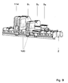
- the plug-in parts S can be designed differently. If a connecting terminal installed in a plug-in part S 1 has to carry large currents, the two-part insulating material housing can be designed twice as wide and higher than the insulating material housing of a plug-in part S 2 designed to carry smaller currents. On the side facing away from the side containing the recess 114, the insulating housing 1 has a recess which cannot be seen in FIG. 9. A side wall of the additional base is guided through this recess, which otherwise borders on the insulating housing in the smaller plug-in part S 2 . A field 120 can also be provided on a side wall of the plug-in parts for attaching a label.
- the insulating housing of the plug-in parts are generally made of a temperature-resistant thermoplastic or thermosetting plastic.
- the housing can therefore be easily colored, for example blue for the neutral conductor N and green and yellow for the protective conductor PE.
- plug-in parts which perform other functions can also be used.
- a plug-in part designed as an empty housing can be used, which serves to separate two conductor rail sections of the N conductor rail from one another.
- the plug-in part may be a cover piece, which may carry a mounting rail profile (plug-in part S 3 according to FIG. 9), onto which parts with additional functions, such as surge arresters or current and voltage transformers, can be snapped on.
Landscapes
- Connections Arranged To Contact A Plurality Of Conductors (AREA)
- Ignition Installations For Internal Combustion Engines (AREA)
- Connector Housings Or Holding Contact Members (AREA)
- Coupling Device And Connection With Printed Circuit (AREA)
Applications Claiming Priority (2)
| Application Number | Priority Date | Filing Date | Title |
|---|---|---|---|
| DE19957277 | 1999-11-29 | ||
| DE19957277A DE19957277A1 (de) | 1999-11-29 | 1999-11-29 | Klemmanordnung für einen Niederspannungsverteiler |
Publications (3)
| Publication Number | Publication Date |
|---|---|
| EP1104047A2 true EP1104047A2 (fr) | 2001-05-30 |
| EP1104047A3 EP1104047A3 (fr) | 2003-04-02 |
| EP1104047B1 EP1104047B1 (fr) | 2005-01-19 |
Family
ID=7930646
Family Applications (1)
| Application Number | Title | Priority Date | Filing Date |
|---|---|---|---|
| EP00811068A Expired - Lifetime EP1104047B1 (fr) | 1999-11-29 | 2000-11-13 | Dispositif de borne à connexion pour distributeur électrique à basse tension |
Country Status (3)
| Country | Link |
|---|---|
| EP (1) | EP1104047B1 (fr) |
| AT (1) | ATE287581T1 (fr) |
| DE (2) | DE19957277A1 (fr) |
Cited By (2)
| Publication number | Priority date | Publication date | Assignee | Title |
|---|---|---|---|---|
| EP1337005B1 (fr) * | 2002-02-14 | 2014-10-29 | ABB Schweiz AG | Pièces de terminaison pour un système de connecteurs à fiches |
| LU505385B1 (de) * | 2023-10-27 | 2025-04-28 | Phoenix Contact Gmbh & Co | Baukastensystem zum Herstellen eines Frontsteckers |
Families Citing this family (6)
| Publication number | Priority date | Publication date | Assignee | Title |
|---|---|---|---|---|
| DE10204992A1 (de) * | 2002-02-06 | 2003-08-14 | Wieland Electric Gmbh | Installations-Einbauelement und Installationsverteiler |
| DE10245939A1 (de) * | 2002-09-30 | 2004-05-27 | Siemens Ag | Vorrichtung zur Energieversorgung eines Gerätes |
| DE202004000523U1 (de) * | 2004-01-15 | 2005-05-25 | Weidmüller Interface GmbH & Co. KG | Anschlußsystem zum Anschluß elektrischer Leiter an ein elektrisches Gerät |
| EP3246995B1 (fr) | 2016-05-17 | 2020-05-13 | Wöhner GmbH & Co. KG Elektrotechnische Systeme | Systeme de barres omnibus |
| DE202017104591U1 (de) * | 2017-08-01 | 2018-11-06 | Wago Verwaltungsgesellschaft Mbh | Sockeleinheit für Reiheneinbaugeräteanordnung |
| CN121528784B (zh) * | 2025-12-08 | 2026-08-04 | 德力西电气有限公司 | 开关组件 |
Family Cites Families (9)
| Publication number | Priority date | Publication date | Assignee | Title |
|---|---|---|---|---|
| CH654696A5 (en) * | 1982-05-28 | 1986-02-28 | Bbc Brown Boveri & Cie | Device for holding and tapping a flat (ribbon) cable |
| ES2013259B3 (es) * | 1985-12-14 | 1990-05-01 | Cmc Carl Maier + Cie Ag | Repartidor de baja tension |
| GB2247351B (en) * | 1990-08-21 | 1995-03-01 | Crabtree Electrical Ind Ltd | Improvements relating to the mounting of circuit breakers |
| DE4235876C2 (de) * | 1992-10-23 | 1994-07-21 | Kathrein Werke Kg | Mit Anschluß- und Verzweigungseinrichtungen versehbarer Leitungsbus |
| CH685412A5 (de) * | 1992-11-11 | 1995-06-30 | Reichle & De Massari Fa | Modulare Mehrfachanschlussleiste für Verteiler und Verteilersysteme im Schwachstrom-Anlagebau. |
| DE19524123C1 (de) * | 1995-05-26 | 1997-02-13 | Phoenix Contact Gmbh & Co | Tragschiene und Stecker zur Kopplung mit einer Tragschiene |
| FR2735290B1 (fr) * | 1995-06-07 | 1997-07-18 | Schneider Electric Sa | Dispositif d'assemblage et de liaison electrique d'appareils modulaires tels des disjoncteurs ou analogues |
| DE19530659C1 (de) * | 1995-08-21 | 1997-02-20 | Weber Ag | Niederspannungs-Sammelschienensystem |
| DE19702233C2 (de) * | 1997-01-23 | 1999-09-30 | Phoenix Contact Gmbh & Co | Anschlußeinrichtung für ein elektrisches Gerät |
-
1999
- 1999-11-29 DE DE19957277A patent/DE19957277A1/de not_active Withdrawn
-
2000
- 2000-11-13 DE DE50009272T patent/DE50009272D1/de not_active Expired - Lifetime
- 2000-11-13 AT AT00811068T patent/ATE287581T1/de active
- 2000-11-13 EP EP00811068A patent/EP1104047B1/fr not_active Expired - Lifetime
Cited By (3)
| Publication number | Priority date | Publication date | Assignee | Title |
|---|---|---|---|---|
| EP1337005B1 (fr) * | 2002-02-14 | 2014-10-29 | ABB Schweiz AG | Pièces de terminaison pour un système de connecteurs à fiches |
| LU505385B1 (de) * | 2023-10-27 | 2025-04-28 | Phoenix Contact Gmbh & Co | Baukastensystem zum Herstellen eines Frontsteckers |
| WO2025088049A1 (fr) * | 2023-10-27 | 2025-05-01 | Phoenix Contact Gmbh & Co. Kg | Système modulaire pour fabriquer un connecteur orienté vers l'avant |
Also Published As
| Publication number | Publication date |
|---|---|
| EP1104047A3 (fr) | 2003-04-02 |
| DE19957277A1 (de) | 2001-05-31 |
| DE50009272D1 (de) | 2005-02-24 |
| EP1104047B1 (fr) | 2005-01-19 |
| ATE287581T1 (de) | 2005-02-15 |
Similar Documents
| Publication | Publication Date | Title |
|---|---|---|
| EP0709917B1 (fr) | Bloc de connexion avec module électronique | |
| EP0678932B1 (fr) | Borne de raccordement et de connexion électrique | |
| EP1290759B1 (fr) | Borne de connexion | |
| EP0198099B1 (fr) | Contacteur en particulier contacteur auxiliaire ou contacteur de moteur | |
| EP2614515B1 (fr) | Appareil de commutation et accessoire du côté connexion | |
| DE68903836T2 (de) | Verbrauchereinheiten. | |
| DE102009016120A1 (de) | Schaltschrank mit steckverbindbarer Sammelschiene | |
| EP0702441B1 (fr) | Appareillage d'installation électrique, notamment pour canalisations de câbles | |
| EP1104047B1 (fr) | Dispositif de borne à connexion pour distributeur électrique à basse tension | |
| DE19818058A1 (de) | Schaltgerät mit einer Schaltkammer-Baugruppe | |
| DE1490752A1 (de) | Elektrische Schaltgeraete tragende Tafel | |
| EP3869644B1 (fr) | Appareil de protection contre les surtensions destiné à l'installation sur un système de barre omnibus, ainsi que module | |
| EP0252512A1 (fr) | Unité de connexion multiple | |
| DE2601849C2 (de) | Reihentrennklemme | |
| EP0762583A2 (fr) | Système de barres omnibus à basse tension | |
| DE19751705C2 (de) | Verrasteter Einbaublock | |
| WO1998047336A1 (fr) | Appareil electrique a deux capots de boitier identiques | |
| DE10005219A1 (de) | Isoliergehäuse zur Befestigung an einer Tragschiene | |
| DE69607136T2 (de) | Schalttafel und Anschlusseinrichtung für elektrische Installationen mit modularen Einrichtungen | |
| DE3046928C2 (de) | Abdeckung für die Klemmen von Schutzschaltern | |
| EP0610710A1 (fr) | Dispositif démontable pour fixer des appareils d'installation électriques | |
| EP1119085B1 (fr) | Fixation rapide pour appareil électrique d'installation | |
| AT504268B1 (de) | Sicherungssockel | |
| EP0355524A2 (fr) | Canalisation pour câble | |
| EP0951104B1 (fr) | Prise, particulièrement un boítier encastrable pour installations électriques |
Legal Events
| Date | Code | Title | Description |
|---|---|---|---|
| PUAI | Public reference made under article 153(3) epc to a published international application that has entered the european phase |
Free format text: ORIGINAL CODE: 0009012 |
|
| AK | Designated contracting states |
Kind code of ref document: A2 Designated state(s): AT BE CH CY DE DK ES FI FR GB GR IE IT LI LU MC NL PT SE TR |
|
| AX | Request for extension of the european patent |
Free format text: AL;LT;LV;MK;RO;SI |
|
| RAP1 | Party data changed (applicant data changed or rights of an application transferred) |
Owner name: ABB SCHWEIZ AG |
|
| PUAL | Search report despatched |
Free format text: ORIGINAL CODE: 0009013 |
|
| AK | Designated contracting states |
Kind code of ref document: A3 Designated state(s): AT BE CH CY DE DK ES FI FR GB GR IE IT LI LU MC NL PT SE TR |
|
| AX | Request for extension of the european patent |
Extension state: AL LT LV MK RO SI |
|
| 17P | Request for examination filed |
Effective date: 20030924 |
|
| AKX | Designation fees paid |
Designated state(s): AT BE CH CY DE DK ES FI FR GB GR IE IT LI LU MC NL PT SE TR |
|
| 17Q | First examination report despatched |
Effective date: 20031119 |
|
| GRAP | Despatch of communication of intention to grant a patent |
Free format text: ORIGINAL CODE: EPIDOSNIGR1 |
|
| GRAS | Grant fee paid |
Free format text: ORIGINAL CODE: EPIDOSNIGR3 |
|
| GRAA | (expected) grant |
Free format text: ORIGINAL CODE: 0009210 |
|
| AK | Designated contracting states |
Kind code of ref document: B1 Designated state(s): AT BE CH CY DE DK ES FI FR GB GR IE IT LI LU MC NL PT SE TR |
|
| PG25 | Lapsed in a contracting state [announced via postgrant information from national office to epo] |
Ref country code: IE Free format text: LAPSE BECAUSE OF FAILURE TO SUBMIT A TRANSLATION OF THE DESCRIPTION OR TO PAY THE FEE WITHIN THE PRESCRIBED TIME-LIMIT Effective date: 20050119 Ref country code: GB Free format text: LAPSE BECAUSE OF FAILURE TO SUBMIT A TRANSLATION OF THE DESCRIPTION OR TO PAY THE FEE WITHIN THE PRESCRIBED TIME-LIMIT Effective date: 20050119 Ref country code: TR Free format text: LAPSE BECAUSE OF FAILURE TO SUBMIT A TRANSLATION OF THE DESCRIPTION OR TO PAY THE FEE WITHIN THE PRESCRIBED TIME-LIMIT Effective date: 20050119 Ref country code: FI Free format text: LAPSE BECAUSE OF FAILURE TO SUBMIT A TRANSLATION OF THE DESCRIPTION OR TO PAY THE FEE WITHIN THE PRESCRIBED TIME-LIMIT Effective date: 20050119 |
|
| REG | Reference to a national code |
Ref country code: GB Ref legal event code: FG4D Free format text: NOT ENGLISH |
|
| REG | Reference to a national code |
Ref country code: CH Ref legal event code: EP |
|
| REG | Reference to a national code |
Ref country code: IE Ref legal event code: FG4D Free format text: GERMAN |
|
| REF | Corresponds to: |
Ref document number: 50009272 Country of ref document: DE Date of ref document: 20050224 Kind code of ref document: P |
|
| PG25 | Lapsed in a contracting state [announced via postgrant information from national office to epo] |
Ref country code: DK Free format text: LAPSE BECAUSE OF FAILURE TO SUBMIT A TRANSLATION OF THE DESCRIPTION OR TO PAY THE FEE WITHIN THE PRESCRIBED TIME-LIMIT Effective date: 20050419 Ref country code: GR Free format text: LAPSE BECAUSE OF FAILURE TO SUBMIT A TRANSLATION OF THE DESCRIPTION OR TO PAY THE FEE WITHIN THE PRESCRIBED TIME-LIMIT Effective date: 20050419 Ref country code: SE Free format text: LAPSE BECAUSE OF FAILURE TO SUBMIT A TRANSLATION OF THE DESCRIPTION OR TO PAY THE FEE WITHIN THE PRESCRIBED TIME-LIMIT Effective date: 20050419 |
|
| PG25 | Lapsed in a contracting state [announced via postgrant information from national office to epo] |
Ref country code: ES Free format text: LAPSE BECAUSE OF FAILURE TO SUBMIT A TRANSLATION OF THE DESCRIPTION OR TO PAY THE FEE WITHIN THE PRESCRIBED TIME-LIMIT Effective date: 20050430 |
|
| GBV | Gb: ep patent (uk) treated as always having been void in accordance with gb section 77(7)/1977 [no translation filed] |
Effective date: 20050119 |
|
| REG | Reference to a national code |
Ref country code: IE Ref legal event code: FD4D |
|
| PG25 | Lapsed in a contracting state [announced via postgrant information from national office to epo] |
Ref country code: CY Free format text: LAPSE BECAUSE OF FAILURE TO SUBMIT A TRANSLATION OF THE DESCRIPTION OR TO PAY THE FEE WITHIN THE PRESCRIBED TIME-LIMIT Effective date: 20051113 |
|
| PLBE | No opposition filed within time limit |
Free format text: ORIGINAL CODE: 0009261 |
|
| STAA | Information on the status of an ep patent application or granted ep patent |
Free format text: STATUS: NO OPPOSITION FILED WITHIN TIME LIMIT |
|
| PG25 | Lapsed in a contracting state [announced via postgrant information from national office to epo] |
Ref country code: BE Free format text: LAPSE BECAUSE OF NON-PAYMENT OF DUE FEES Effective date: 20051130 Ref country code: LU Free format text: LAPSE BECAUSE OF NON-PAYMENT OF DUE FEES Effective date: 20051130 Ref country code: MC Free format text: LAPSE BECAUSE OF NON-PAYMENT OF DUE FEES Effective date: 20051130 |
|
| ET | Fr: translation filed | ||
| 26N | No opposition filed |
Effective date: 20051020 |
|
| BERE | Be: lapsed |
Owner name: ABB SCHWEIZ A.G. Effective date: 20051130 |
|
| PG25 | Lapsed in a contracting state [announced via postgrant information from national office to epo] |
Ref country code: PT Free format text: LAPSE BECAUSE OF NON-PAYMENT OF DUE FEES Effective date: 20050619 |
|
| PGFP | Annual fee paid to national office [announced via postgrant information from national office to epo] |
Ref country code: NL Payment date: 20141119 Year of fee payment: 15 |
|
| REG | Reference to a national code |
Ref country code: FR Ref legal event code: PLFP Year of fee payment: 16 |
|
| REG | Reference to a national code |
Ref country code: NL Ref legal event code: MM Effective date: 20151201 |
|
| PG25 | Lapsed in a contracting state [announced via postgrant information from national office to epo] |
Ref country code: NL Free format text: LAPSE BECAUSE OF NON-PAYMENT OF DUE FEES Effective date: 20151201 |
|
| REG | Reference to a national code |
Ref country code: FR Ref legal event code: PLFP Year of fee payment: 17 |
|
| REG | Reference to a national code |
Ref country code: FR Ref legal event code: PLFP Year of fee payment: 18 |
|
| PGFP | Annual fee paid to national office [announced via postgrant information from national office to epo] |
Ref country code: DE Payment date: 20191121 Year of fee payment: 20 |
|
| PGFP | Annual fee paid to national office [announced via postgrant information from national office to epo] |
Ref country code: IT Payment date: 20191128 Year of fee payment: 20 Ref country code: FR Payment date: 20191120 Year of fee payment: 20 |
|
| PGFP | Annual fee paid to national office [announced via postgrant information from national office to epo] |
Ref country code: CH Payment date: 20191121 Year of fee payment: 20 Ref country code: AT Payment date: 20191121 Year of fee payment: 20 |
|
| REG | Reference to a national code |
Ref country code: DE Ref legal event code: R071 Ref document number: 50009272 Country of ref document: DE |
|
| REG | Reference to a national code |
Ref country code: CH Ref legal event code: PL |
|
| REG | Reference to a national code |
Ref country code: AT Ref legal event code: MK07 Ref document number: 287581 Country of ref document: AT Kind code of ref document: T Effective date: 20201113 |