EP1104051A2 - Verbinder - Google Patents
Verbinder Download PDFInfo
- Publication number
- EP1104051A2 EP1104051A2 EP00310528A EP00310528A EP1104051A2 EP 1104051 A2 EP1104051 A2 EP 1104051A2 EP 00310528 A EP00310528 A EP 00310528A EP 00310528 A EP00310528 A EP 00310528A EP 1104051 A2 EP1104051 A2 EP 1104051A2
- Authority
- EP
- European Patent Office
- Prior art keywords
- lance
- connection terminal
- connector
- groove
- end portion
- Prior art date
- Legal status (The legal status is an assumption and is not a legal conclusion. Google has not performed a legal analysis and makes no representation as to the accuracy of the status listed.)
- Granted
Links
- 238000003780 insertion Methods 0.000 claims abstract description 47
- 238000006073 displacement reaction Methods 0.000 claims abstract description 30
- 238000001514 detection method Methods 0.000 claims abstract description 23
- 230000037431 insertion Effects 0.000 claims description 20
- 230000000717 retained effect Effects 0.000 claims description 5
- 238000005192 partition Methods 0.000 abstract description 19
- 238000010276 construction Methods 0.000 description 14
- 238000007689 inspection Methods 0.000 description 6
- 239000004020 conductor Substances 0.000 description 4
- 230000005489 elastic deformation Effects 0.000 description 3
- 230000013011 mating Effects 0.000 description 2
- 229920003002 synthetic resin Polymers 0.000 description 2
- 239000000057 synthetic resin Substances 0.000 description 2
- 230000001154 acute effect Effects 0.000 description 1
- 239000000470 constituent Substances 0.000 description 1
- 230000003247 decreasing effect Effects 0.000 description 1
- 230000000694 effects Effects 0.000 description 1
- 239000002184 metal Substances 0.000 description 1
- 238000000034 method Methods 0.000 description 1
- 238000012986 modification Methods 0.000 description 1
- 230000004048 modification Effects 0.000 description 1
Images



Classifications
-
- H—ELECTRICITY
- H01—ELECTRIC ELEMENTS
- H01R—ELECTRICALLY-CONDUCTIVE CONNECTIONS; STRUCTURAL ASSOCIATIONS OF A PLURALITY OF MUTUALLY-INSULATED ELECTRICAL CONNECTING ELEMENTS; COUPLING DEVICES; CURRENT COLLECTORS
- H01R13/00—Details of coupling devices of the kinds covered by groups H01R12/70 or H01R24/00 - H01R33/00
- H01R13/40—Securing contact members in or to a base or case; Insulating of contact members
- H01R13/42—Securing in a demountable manner
- H01R13/422—Securing in resilient one-piece base or case, e.g. by friction; One-piece base or case formed with resilient locking means
- H01R13/4223—Securing in resilient one-piece base or case, e.g. by friction; One-piece base or case formed with resilient locking means comprising integral flexible contact retaining fingers
Definitions
- the present invention relates to a connector, comprising connection terminals and a connector housing having terminal receiving chambers. More particularly, the present invention relates to a connector in which a lance displacement detection pin of a connector inspecting instrument is inserted into the terminal receiving chamber so as to detect a half-insertion condition of the connection terminal.
- a connector used for connecting vehicle's wire harnesses or the like together, comprises electrically-conductive connection terminals of a known construction, and a connector housing of a synthetic resin for receiving the connection terminals.
- Terminal receiving chambers for respectively receiving the connection terminals are formed in the connector housing.
- the terminal receiving chambers extend through the connector housing from a front end surface thereof to a rear end surface thereof, and terminal insertion ports are formed in the rear end surface of the connector housing, and connection ports for respectively receiving mating connection terminals are formed in the front end surface of the connector housing.
- a lance for retaining the connection terminal, received in the terminal receiving chamber, and an elastic displacement-allowing space for the lance are formed within each terminal receiving chamber.
- the lance has a tongue-like distal end portion, and a retaining projection for engagement with the connection terminal is formed on the distal end portion of the lance.
- a lance displacement detection pin of a connector inspecting instrument is inserted into the elastic displacement-allowing space through the insertion port, formed in the front end surface, so as to detect a half-insertion condition of the connection terminal.
- the lance in a half-insertion condition of the connection terminal, the lance is kept elastically deformed by the connection terminal (The lance is kept stranded on the connection terminal, with the retaining projection held in contact therewith).
- the distal end (the distal end portion and the retaining projection) of the lance is displaced with respect to the proper retaining position, and is disposed in the elastic displacement-allowing space.
- this pin when the lance displacement detection pin is inserted into the elastic displacement-allowing space, this pin abuts against the distal end portion of the lance, thereby detecting the half-insertion condition of the connection terminal.
- the connector housing need to be so formed that the distal end of the lance can be displaced as much as possible so that the half-insertion condition of the connection terminal can be positively detected.
- a connector which comprises a connector housing including a terminal receiving chamber into which a connection terminal is insertable, the terminal receiving chamber having a displacement-allowing space, a lance formed in the terminal receiving chamber, the lance having a distal end portion which extends in an inserting direction of the connection terminal, wherein the connection terminal is inserted into the terminal receiving chamber while pushing the lance to enter the distal end portion thereof into the displacement-allowing space, and is retained by the lance in a complete insertion state thereof to be prevented from moving in a withdrawing direction opposite to the inserting direction, and a groove extending in the inserting direction of the connection terminal, the groove being formed in a wall of the terminal receiving chamber which is opposed to the connection terminal, and has the displacement-allowing space formed therein, wherein the distal end portion of the lance enters the groove in accordance with insertion of the connection terminal, and wherein length of the distal end portion of the lance is determined in accordance with a depth of the
- the lance may be formed in a cantilever manner with respect to the connector housing to be elastically deformable.
- the groove, into which the distal end portion of the lance can be inserted is formed in the wall of the terminal receiving chamber toward which the distal end portion of the elastically-deformed lance moves, that is, the wall to which the received connection terminal is opposed through the displacement allowing space disposed therebetween.
- the length of the distal end portion of the lance is determined in accordance with a depth of the groove.
- a lance displacement detection pin of a connector inspecting instrument for detecting a half-insertion condition of the connection terminal can be inserted into the groove, and therefore a half-insertion condition of the connection terminal can be positively detected.
- the lance may have a retaining projection which engages the connection terminal to be retained in the terminal receiving chamber.
- the distal end portion of the lance is projected from the retaining projection so as to enter the groove in accordance with insertion of the connection terminal.
- the connector of the present invention is not so designed that the projecting height of the retaining projection on the lance is greater. Accordingly, a terminal inserting force, required for inserting the connection terminal during the assembling operation, is not large.
- the wall of the terminal receiving chamber may be formed stepwise to thereby form the groove therein.
- the wall in which the groove is formed it may be one of walls of the terminal receiving chamber which define the displacement-allowing space.
- the location of the displacement-allowing space it may be disposed forwardly of a proximal end portion of the lance in the inserting direction of the connection terminal.
- the groove extends from an insertion port for the lance displacement detection pin to a vicinity of a portion of the wall with which the proximal end portion of the lance is integrally formed.
- the elastic deformation of the lance is not influenced by the groove.
- the force of retaining of the connection terminal by the lance is not lowered by the groove.
- a terminal inserting force, required for inserting the connection terminal during the assembling operation is not large.
- a width of the groove in a direction perpendicular to the inserting direction of the connection terminal is smaller than a width of the displacement-allowing space in the same direction as the width of the groove.
- the structure is not complicated. And besides, the terminal inserting force, required for inserting the connection terminal during the assembling operation, as well as the force of retaining of the connection terminal by the lance, is not affected.
- Figs. 1 and 2 show a connector 1 used for connecting vehicle's wire harnesses or the like together.
- the connector 1 comprises a plurality of connection terminals 2 (only one of which is shown), and a connector housing 3 for receiving the plurality of connection terminals 2.
- the connector 1 is so constructed that a half-insertion condition can be positively detected by the connector inspecting instrument 4.
- connection terminal 2 is formed by pressing an electrically-conductive metal sheet, and this connection terminal includes an electrical contact portion 5 and a wire connection portion 6.
- the electrical contact portion 5 includes a base plate portion 10, a pair of resilient curl portions 11 and 11, and a pair of electrical contact piece portions 12 and 12 extending respectively from the resilient curl portions 11 and 11 and bent slightly obliquely upwardly at a small angle relative to the curl portions 11 and 11, respectively.
- a mating connection terminal (not shown) in the form of a male tab-like terminal can be inserted into the electrical contact portion 5 to be connected thereto.
- the wire connection portion 6 is formed in continuous relation to the electric contact portion 5, and includes conductor clamping portions 13 and 13 (only one of which is shown) for holding the conductor 8, and sheath clamping portions 14 and 14 (only one of which is shown) for holding the sheath 7. By compressively deforming the conductor clamping portions 13 and 13 and the sheath clamping portions 14 and 14 by pressing, the wire 9 is secured to the connection terminal 2.
- the connector housing 3 is molded into a rectangular box-shape, using a synthetic resin.
- the connector housing 3 has a plurality of terminal receiving chambers 15 (only one of which is shown) for respectively receiving the plurality of connection terminals 2.
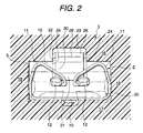
- Each of the terminal receiving chamber 15 extends through the connector housing 3 from a front side thereof to a rear side thereof, and is defined by an upper partition wall 16, a lower partition wall 17, a right partition wall 18 and a left partition wall 19 (see Fig. 2).
- a lance 22, a groove 23 and an elastic displacement-allowing space 24 are formed within the terminal receiving chamber 15.
- Connection ports 25 and detection pin insertion ports 26 are formed in a front wall 20 of the connector housing 3 which forms part of the terminal receiving chambers 15.
- Terminal insertion ports 27, communicating respectively with the terminal receiving chambers 15, are formed in a rear end 21 of the connector housing 3.
- the upper partition wall 16 is formed by an upper wall of the connector housing 3 or the lower partition wall 17 of other terminal receiving chamber 15.
- the lower partition wall 17 is formed by a lower wall of the connector housing 3 or the upper partition wall 16 of other terminal receiving chamber 15.
- the left partition wall 18 and the right partition wall 19 are formed respectively by a left wall and a right wall of the connector housing 3, or by the right partition wall 19 of other terminal receiving chamber 15 and the left partition wall 18 of other terminal receiving chamber 15, respectively.
- the upper partition wall 16 is opposed to the pair of resilient curl portions 11 and 11 of the connection terminal 2 received in the terminal receiving chamber.
- the lance 22 has elasticity, and has a cantilever arm-like shape defined by a proximal end portion 28, an intermediate portion 29 and a distal end portion 30.
- a retaining projection 31 is formed on the lance 22 generally at the boundary between the intermediate portion 29 and the distal end portion 30.
- the distal end portion 30 of the lance 22 extends in a direction of insertion of the connection terminal 2, and when the connection terminal 2 is completely received in the terminal receiving chamber 15, the retaining projection 31 is engaged with the connection terminal 2 to prevent the connection terminal 2 from moving in a withdrawing direction opposite to the direction of insertion of the connection terminal 2.
- the proximal end portion 28 is formed integrally on a lance-forming portion 32 disposed at an intermediate portion of the upper partition wall 16. This proximal end portion 28 projects downwardly a small distance from the lance-forming portion 32.
- the intermediate portion 29 extends from a projecting distal end of the proximal end portion 28 in the direction of insertion of the connection terminal 2.
- the intermediate portion 29 is slightly tapering (that is, decreasing in transverse cross-sectional area) progressively toward its distal end.
- the distal end portion 30 is formed into a tongue-like shape, and an upper edge or corner of this distal end portion 30, disposed close to the upper partition wall 16, is formed into an acute angle as seen from its cross-sectional view. Thanks to the provision of the groove 23, the distal end portion 30 has a larger length (determined in accordance with the depth of the groove 23) as compared with the related construction. Thus, the distal end portion 30 is larger in length as compared with the related construction, and therefore when the lance 22 is elastically deformed by the connection terminal 2, the amount of displacement of the distal end portion 30 is larger as compared with the related construction.
- the retaining projection 31 can engage the rear ends of the pair of resilient curl portions 11 and 11. When the lance 22 is bent (elastically deformed) in a half-insertion condition of the connection terminal, the retaining projection 31 rides on those surfaces of the pair of resilient curl portions 11 and 11 facing the upper partition wall 16.
- the groove 23 is formed in the upper partition wall 16, and the distal end portion 30 of the lance 22, elastically deformed by the connection terminal 2, is inserted in this groove 23.
- the groove 23 extends in the direction of insertion of the connection terminal 2, and the lance displacement detection pin 35 of the connector inspecting instrument 4 (described later) can be inserted into and removed from this groove 23.
- the groove 23 is recessed slightly with respect to the lance-forming portion 32 so as not to affect the elastic deformation of the lance 22.
- the depth of the groove 23 is determined in accordance with the length of the distal end portion 30 of the lance 22.
- the width of the groove 23 (that is, its dimension in a direction perpendicular to the terminal-inserting direction and the direction of the depth of this groove) is so determined that at least the distal end portion 30 of the lance 22 can be inserted into the groove 23.
- the width of the groove 23 is smaller than the width of the elastic displacement-allowing space 24.
- Part of the detection pin insertion port 26 is formed into a shape corresponding to the cross-sectional shape of the groove 23 (The structure is simplified).
- the elastic displacement-allowing space 24 is disposed forwardly of the proximal end portion 28 of the lance 22 in the inserting direction, and allows the elastic displacement of the lance 22.
- the elastic displacement-allowing space 24 is formed over a region from the groove 23 to the pair of resilient curl portions 11 and 11.
- the connector inspecting instrument 4 includes a plurality of inspection pin portions 33 (corresponding in number to the connection terminals 2 and also to the terminal receiving chambers 15).
- the inspection pin portion 33 has an electrical contact pin 34 and the lance displacement detection pin 35.
- the electrical contact pin 34 when inserted into the terminal receiving chamber 15, contacts the electrical contact portion 5 of the connection terminal 2, and the lance displacement detection pin 35 can abut against the lance 22 in a half-insertion condition of the connection terminal.
- a half-insertion condition of the connection terminal 2 can be detected by the use of the connector inspecting instrument 4 of a known construction (disclosed, for example, in Unexamined Japanese Patent Publication No. Hei. 7-113836). Therefore, the showing of this connector inspecting instrument is simplified in the drawings.
- the electrical contact pin 34 and the lance displacement detection pin 35 are not electrically connected to each other.
- connection terminals 2 are inserted respectively into the terminal receiving chambers 15 in the connector housing 3 to be received respectively in these chambers, thereby assembling the connector 1. More specifically, the connection terminal 2 is inserted through the terminal insertion port 27 in a direction of arrow P (that is, the above inserting direction), and is retainingly engaged with the lance 22, thus completing the inserting and receiving operation. This operation is effected for each connection terminal 2, and by doing so, the sequential connector-assembling operation is completed (see Fig. 1 also).
- connection terminal 2 When the connection terminal 2 is inserted into the terminal receiving chamber 15, the electrical contact portion 5 of the connection terminal 2 is brought into engagement with the lance 22, so that the lance 22 is elastically deformed (in a direction of arrow Q) in the elastic displacement-allowing space 24. At this time, the distal end portion 30 of the elastically-deformed lance 22 is inserted into the groove 23. Also, the retaining projection 31 rides on the pair of resilient curl portions 11 and 11. Then, when the connection terminal 2 is further pushed to be inserted, the lance 22 is restored into its original condition as shown in Fig. 1, the retaining projection 31, riding on the curl portions 11 and 11, becomes engaged with the rear ends of these curl portions 11 and 11. As a result, the connection terminal 2 is retained, and therefore is prevented from moving in a withdrawing direction (opposite to the direction of arrow P).
- connection terminal 2 when the connection terminal 2 is kept in a half-insertion condition in the terminal receiving chamber 15, the lance displacement detection pin 35 abuts against the distal end portion 30 of the elastically-deformed lance 22. The movement of the inspection pin portion 33 (or the connector 1) is prevented, and the electrical connection of the electrical contact pin 34 to the connection terminal 2 is prevented. Therefore, the half-insertion condition of the connection terminal 2 can be detected.
- the connector 1 has the groove 23 formed in the upper partition wall 16 of the terminal receiving chamber 15, and the lance displacement detection pin 35 of the connector inspecting instrument 4 for detecting a half-insertion condition of the connection terminal 2, as well as the distal end portion 30 of the lance 22, can be inserted into and removed from the groove 23. And besides, the distal end portion 30 is projected longer (as compared with the related construction) in accordance with the depth of the groove 23, and therefore when the connection terminal 2 is received in the terminal receiving chamber 15 in the connector housing 3, so that the lance 22 is elastically deformed by the connection terminal 2, the amount of displacement of the distal end portion 30 of the lance 22 is larger as compared with the related construction. In a half-insertion condition of the connection terminal 2, also, the amount of displacement of the distal end portion 30 of the lance 22 is larger.
- connection terminal 2 When the amount of displacement is thus large, a half-insertion condition of the connection terminal 2 can be positively detected by the connector inspecting instrument 4.
- the height of projecting of the retaining projection 31 on the lance 22 is not larger as compared with the related construction, and therefore the terminal inserting force, required for inserting the connection terminal 2 during the assembling operation, is maintained at the same level as obtained with the related construction.
- the connector can be of such a construction that the terminal receiving chambers 15 are arranged in two (upper and lower) rows, or are juxtaposed in a row.
- the connector comprises the connection terminals, and the connector housing having the terminal receiving chambers for respectively receiving the connection terminals.
- the lance and the elastic displacement-allowing space are formed within the terminal receiving chamber.
- the groove is formed in the wall of the terminal receiving chamber which is opposed to the connection terminal, and has the elastic displacement-allowing space formed therein, and the lance displacement detection pin of the connector inspecting instrument for detecting a half-insertion condition of the connection terminal, as well as the distal end portion of the lance, can be inserted into and removed from the groove.
- the distal end portion of the lance is projected in accordance with the depth of the groove.
- the amount of displacement of the distal end portion of the lance is larger as compared with the related construction.
- the amount of displacement of the distal end portion of the lance is larger.
- the lance displacement detection pin of the connector inspecting instrument for detecting a half-insertion condition of the connection terminal can be inserted into the groove.
- connection terminal can be positively detected by the connector inspecting instrument.
- the height of projecting of the retaining projection on the lance is not large, and therefore the terminal inserting force, required for inserting the connection terminal during the assembling operation, is not large.
- the connector in which the distal end portion of the lance can be displaced as much as possible without increasing the terminal inserting force.
- the groove for receiving the distal end portion of the lance extends from the insertion port for the lance displacement detection pin to the vicinity of the lance-forming portion on which the proximal end portion of the lance is formed integrally. Therefore, the elastic deformation of the lance is not influenced by the groove, and therefore the lance can maintain its performance.
- the width of the groove is smaller than the width of the elastic displacement-allowing space, and therefore the structure can be simplified.
Landscapes
- Connector Housings Or Holding Contact Members (AREA)
- Details Of Connecting Devices For Male And Female Coupling (AREA)
Applications Claiming Priority (2)
| Application Number | Priority Date | Filing Date | Title |
|---|---|---|---|
| JP33735599 | 1999-11-29 | ||
| JP33735599A JP2001155810A (ja) | 1999-11-29 | 1999-11-29 | コネクタ |
Publications (3)
| Publication Number | Publication Date |
|---|---|
| EP1104051A2 true EP1104051A2 (de) | 2001-05-30 |
| EP1104051A3 EP1104051A3 (de) | 2002-06-26 |
| EP1104051B1 EP1104051B1 (de) | 2004-02-04 |
Family
ID=18307851
Family Applications (1)
| Application Number | Title | Priority Date | Filing Date |
|---|---|---|---|
| EP00310528A Expired - Lifetime EP1104051B1 (de) | 1999-11-29 | 2000-11-28 | Verbinder |
Country Status (4)
| Country | Link |
|---|---|
| US (1) | US6375502B2 (de) |
| EP (1) | EP1104051B1 (de) |
| JP (1) | JP2001155810A (de) |
| DE (1) | DE60008069T2 (de) |
Cited By (3)
| Publication number | Priority date | Publication date | Assignee | Title |
|---|---|---|---|---|
| EP2337158A1 (de) * | 2009-12-16 | 2011-06-22 | Sumitomo Wiring Systems, Ltd. | Verbinder |
| WO2012095934A1 (en) * | 2011-01-12 | 2012-07-19 | Yazaki Corporation | Terminal locking structure in connector housing |
| CN110635292A (zh) * | 2018-06-21 | 2019-12-31 | 矢崎总业株式会社 | 连接器 |
Families Citing this family (22)
| Publication number | Priority date | Publication date | Assignee | Title |
|---|---|---|---|---|
| EP1585199B1 (de) * | 2001-09-04 | 2009-06-24 | Sumitomo Wiring Systems, Ltd. | Steckverbinder und Stecker |
| JP3775283B2 (ja) * | 2001-11-06 | 2006-05-17 | 住友電装株式会社 | コネクタ |
| JP3855748B2 (ja) * | 2001-11-29 | 2006-12-13 | 住友電装株式会社 | コネクタ |
| CN100530835C (zh) * | 2002-09-25 | 2009-08-19 | 三菱电线工业株式会社 | 电连接器 |
| JP4254482B2 (ja) * | 2003-10-28 | 2009-04-15 | 住友電装株式会社 | コネクタ |
| JP4392360B2 (ja) * | 2005-02-02 | 2009-12-24 | 住友電装株式会社 | 端子金具 |
| US7438585B2 (en) * | 2006-03-07 | 2008-10-21 | Delphi Technologies, Inc. | Electrical connector terminal housing |
| ES2321148B1 (es) * | 2006-04-20 | 2010-03-05 | Emdep-3 S.L. | Dispositivo para comprobar el cierre en conectores electricos. |
| KR100796024B1 (ko) | 2006-05-30 | 2008-01-21 | 한국단자공업 주식회사 | 터미널의 이중록킹 해제구 및 그 해제방법 |
| JP2008305601A (ja) * | 2007-06-06 | 2008-12-18 | Sumitomo Wiring Syst Ltd | コネクタ及び端子金具 |
| JP2011048945A (ja) * | 2009-08-25 | 2011-03-10 | Sumitomo Wiring Syst Ltd | コネクタ |
| US8266798B2 (en) | 2009-09-18 | 2012-09-18 | Delphi Technologies, Inc. | Method of making an improved electrical connection with sealed cable core and a terminal |
| US7905755B1 (en) | 2009-09-18 | 2011-03-15 | Delphi Technologies, Inc. | Electrical terminal connection with sealed core crimp |
| US7954235B2 (en) * | 2009-09-18 | 2011-06-07 | Delphi Technologies, Inc. | Method of making a seal about a copper-based terminal |
| JP5618667B2 (ja) * | 2010-07-20 | 2014-11-05 | 矢崎総業株式会社 | コネクタ検査システム |
| JP6534213B2 (ja) * | 2015-10-27 | 2019-06-26 | ヒロセ電機株式会社 | 端子検査機構を有した基板接続コネクタ |
| US10181679B1 (en) * | 2017-10-20 | 2019-01-15 | Lear Corporation | Electrical connector with terminal position assurance |
| US10218124B1 (en) * | 2017-10-20 | 2019-02-26 | Lear Corporation | Electrical connector with terminal position assurance |
| EP3499654B1 (de) * | 2017-12-13 | 2023-09-06 | Aptiv Technologies Limited | Stromverteilungsanordnung |
| US10312624B1 (en) * | 2018-04-20 | 2019-06-04 | Delphi Technologies, Llc | Connector with primary lock reinforcement |
| JP7007724B2 (ja) * | 2018-06-18 | 2022-01-25 | 日本圧着端子製造株式会社 | コネクタ |
| CN222365750U (zh) * | 2024-01-26 | 2025-01-17 | 东莞市凯华电子有限公司 | 一种可更换式插拔座 |
Family Cites Families (7)
| Publication number | Priority date | Publication date | Assignee | Title |
|---|---|---|---|---|
| US4557542A (en) * | 1984-06-11 | 1985-12-10 | Amp Incorporated | Connector with means for retaining terminals and verifying seating |
| JPH07114131B2 (ja) * | 1990-05-16 | 1995-12-06 | 矢崎総業株式会社 | コネクタ |
| JP3029081B2 (ja) * | 1993-08-24 | 2000-04-04 | 矢崎総業株式会社 | コネクタ検査具 |
| US5859534A (en) * | 1993-11-18 | 1999-01-12 | Sumitomo Wiring Systems | Connector examination and correction devices and methods examining and correcting same |
| JP2604378Y2 (ja) * | 1993-12-06 | 2000-05-08 | 矢崎総業株式会社 | フロントホルダ付き二重係止コネクタ |
| FR2726368B3 (fr) * | 1994-11-02 | 1996-12-27 | Amp France | Appareil de controle de l'assemblage de bornes |
| JP3758104B2 (ja) * | 1997-05-20 | 2006-03-22 | 矢崎総業株式会社 | コネクタ |
-
1999
- 1999-11-29 JP JP33735599A patent/JP2001155810A/ja not_active Abandoned
-
2000
- 2000-11-28 DE DE60008069T patent/DE60008069T2/de not_active Expired - Fee Related
- 2000-11-28 EP EP00310528A patent/EP1104051B1/de not_active Expired - Lifetime
- 2000-11-29 US US09/725,193 patent/US6375502B2/en not_active Expired - Fee Related
Cited By (5)
| Publication number | Priority date | Publication date | Assignee | Title |
|---|---|---|---|---|
| EP2337158A1 (de) * | 2009-12-16 | 2011-06-22 | Sumitomo Wiring Systems, Ltd. | Verbinder |
| WO2012095934A1 (en) * | 2011-01-12 | 2012-07-19 | Yazaki Corporation | Terminal locking structure in connector housing |
| US9028277B2 (en) | 2011-01-12 | 2015-05-12 | Yazaki Corporation | Terminal locking structure in connector housing |
| CN110635292A (zh) * | 2018-06-21 | 2019-12-31 | 矢崎总业株式会社 | 连接器 |
| CN110635292B (zh) * | 2018-06-21 | 2021-02-12 | 矢崎总业株式会社 | 连接器 |
Also Published As
| Publication number | Publication date |
|---|---|
| JP2001155810A (ja) | 2001-06-08 |
| DE60008069D1 (de) | 2004-03-11 |
| US6375502B2 (en) | 2002-04-23 |
| US20010002347A1 (en) | 2001-05-31 |
| EP1104051B1 (de) | 2004-02-04 |
| DE60008069T2 (de) | 2004-12-23 |
| EP1104051A3 (de) | 2002-06-26 |
Similar Documents
| Publication | Publication Date | Title |
|---|---|---|
| EP1104051B1 (de) | Verbinder | |
| US6638109B2 (en) | Connector with a side retainer | |
| US6626701B2 (en) | Connector | |
| EP1137118B1 (de) | Verbinder mit einem Port zum Einführen eines Kontaktstiftes eines Leitungstestwerkzeugs | |
| EP0389955B1 (de) | Doppelt verriegelnder Verbinder für einen elektrischen Endkontakt | |
| US6582242B2 (en) | Electrical connector with increased contact reliability | |
| US7144281B2 (en) | Female terminal fitting and a blank for a plurality of terminal fittings | |
| US5273456A (en) | Mate sensing connector system | |
| EP1137108A1 (de) | Elektrischer Kontakt | |
| US7544106B2 (en) | Terminal fitting | |
| US9190753B2 (en) | Electrical connector | |
| US7766697B2 (en) | Connector | |
| JP2001357921A (ja) | 電気コネクタ | |
| US20210167542A1 (en) | Connector | |
| JP3060302B2 (ja) | 端子位置保証機構を備えた電気コネクタ | |
| JPH09283203A (ja) | リテーナを有する電気コネクタ | |
| EP1168519A2 (de) | Verbinder | |
| EP0657968B1 (de) | Verbinder mit Verriegelungserkennung | |
| US6589080B2 (en) | Terminal fitting and a connector | |
| JP3717057B2 (ja) | コネクタのサイドスペーサ構造 | |
| US6334790B2 (en) | Electrical connection and housing having a lance in a terminal accommodation chamber | |
| US5647778A (en) | Electrical connector | |
| CN112909608A (zh) | 端子零件 | |
| EP0948095A1 (de) | Elektrischer Steckverbinder | |
| JP3601773B2 (ja) | 端子 |
Legal Events
| Date | Code | Title | Description |
|---|---|---|---|
| PUAI | Public reference made under article 153(3) epc to a published international application that has entered the european phase |
Free format text: ORIGINAL CODE: 0009012 |
|
| AK | Designated contracting states |
Kind code of ref document: A2 Designated state(s): AT BE CH CY DE DK ES FI FR GB GR IE IT LI LU MC NL PT SE TR |
|
| AX | Request for extension of the european patent |
Free format text: AL;LT;LV;MK;RO;SI |
|
| PUAL | Search report despatched |
Free format text: ORIGINAL CODE: 0009013 |
|
| AK | Designated contracting states |
Kind code of ref document: A3 Designated state(s): AT BE CH CY DE DK ES FI FR GB GR IE IT LI LU MC NL PT SE TR |
|
| AX | Request for extension of the european patent |
Free format text: AL;LT;LV;MK;RO;SI |
|
| RIC1 | Information provided on ipc code assigned before grant |
Free format text: 7H 01R 13/629 A, 7H 01R 13/422 B |
|
| 17P | Request for examination filed |
Effective date: 20021205 |
|
| AKX | Designation fees paid |
Designated state(s): DE FR GB |
|
| GRAP | Despatch of communication of intention to grant a patent |
Free format text: ORIGINAL CODE: EPIDOSNIGR1 |
|
| GRAS | Grant fee paid |
Free format text: ORIGINAL CODE: EPIDOSNIGR3 |
|
| GRAA | (expected) grant |
Free format text: ORIGINAL CODE: 0009210 |
|
| AK | Designated contracting states |
Kind code of ref document: B1 Designated state(s): DE FR GB |
|
| REG | Reference to a national code |
Ref country code: GB Ref legal event code: FG4D |
|
| REG | Reference to a national code |
Ref country code: IE Ref legal event code: FG4D |
|
| REF | Corresponds to: |
Ref document number: 60008069 Country of ref document: DE Date of ref document: 20040311 Kind code of ref document: P |
|
| ET | Fr: translation filed | ||
| PGFP | Annual fee paid to national office [announced via postgrant information from national office to epo] |
Ref country code: FR Payment date: 20041109 Year of fee payment: 5 |
|
| PGFP | Annual fee paid to national office [announced via postgrant information from national office to epo] |
Ref country code: GB Payment date: 20041124 Year of fee payment: 5 |
|
| PGFP | Annual fee paid to national office [announced via postgrant information from national office to epo] |
Ref country code: DE Payment date: 20041125 Year of fee payment: 5 |
|
| PLBE | No opposition filed within time limit |
Free format text: ORIGINAL CODE: 0009261 |
|
| STAA | Information on the status of an ep patent application or granted ep patent |
Free format text: STATUS: NO OPPOSITION FILED WITHIN TIME LIMIT |
|
| 26N | No opposition filed |
Effective date: 20041105 |
|
| PG25 | Lapsed in a contracting state [announced via postgrant information from national office to epo] |
Ref country code: GB Free format text: LAPSE BECAUSE OF NON-PAYMENT OF DUE FEES Effective date: 20051128 |
|
| PG25 | Lapsed in a contracting state [announced via postgrant information from national office to epo] |
Ref country code: DE Free format text: LAPSE BECAUSE OF NON-PAYMENT OF DUE FEES Effective date: 20060601 |
|
| GBPC | Gb: european patent ceased through non-payment of renewal fee |
Effective date: 20051128 |
|
| PG25 | Lapsed in a contracting state [announced via postgrant information from national office to epo] |
Ref country code: FR Free format text: LAPSE BECAUSE OF NON-PAYMENT OF DUE FEES Effective date: 20060731 |
|
| REG | Reference to a national code |
Ref country code: FR Ref legal event code: ST Effective date: 20060731 |