EP1104086A1 - Ansteuersystem für eine rotierende elektrische Permanent-Magnet Maschine für sehr hohe Drehzahlen - Google Patents
Ansteuersystem für eine rotierende elektrische Permanent-Magnet Maschine für sehr hohe Drehzahlen Download PDFInfo
- Publication number
- EP1104086A1 EP1104086A1 EP00118285A EP00118285A EP1104086A1 EP 1104086 A1 EP1104086 A1 EP 1104086A1 EP 00118285 A EP00118285 A EP 00118285A EP 00118285 A EP00118285 A EP 00118285A EP 1104086 A1 EP1104086 A1 EP 1104086A1
- Authority
- EP
- European Patent Office
- Prior art keywords
- permanent magnet
- magnet type
- content percentage
- order component
- synchronous motor
- Prior art date
- Legal status (The legal status is an assumption and is not a legal conclusion. Google has not performed a legal analysis and makes no representation as to the accuracy of the status listed.)
- Withdrawn
Links
- 230000001360 synchronised effect Effects 0.000 claims abstract description 69
- 229910000831 Steel Inorganic materials 0.000 claims description 46
- 239000010959 steel Substances 0.000 claims description 46
- 239000000696 magnetic material Substances 0.000 claims description 10
- 238000004804 winding Methods 0.000 claims description 9
- 229920000049 Carbon (fiber) Polymers 0.000 claims description 6
- 239000004917 carbon fiber Substances 0.000 claims description 6
- 230000002787 reinforcement Effects 0.000 claims description 6
- 239000000463 material Substances 0.000 claims description 5
- 238000003780 insertion Methods 0.000 claims description 4
- 230000037431 insertion Effects 0.000 claims description 4
- 244000287680 Garcinia dulcis Species 0.000 claims description 2
- 229910001172 neodymium magnet Inorganic materials 0.000 abstract description 5
- 230000004907 flux Effects 0.000 description 11
- 238000001816 cooling Methods 0.000 description 5
- 238000002474 experimental method Methods 0.000 description 5
- 239000004918 carbon fiber reinforced polymer Substances 0.000 description 3
- 230000006835 compression Effects 0.000 description 3
- 238000007906 compression Methods 0.000 description 3
- 230000000694 effects Effects 0.000 description 2
- 239000003566 sealing material Substances 0.000 description 2
- RTAQQCXQSZGOHL-UHFFFAOYSA-N Titanium Chemical group [Ti] RTAQQCXQSZGOHL-UHFFFAOYSA-N 0.000 description 1
- 239000000470 constituent Substances 0.000 description 1
- 238000013016 damping Methods 0.000 description 1
- 238000006073 displacement reaction Methods 0.000 description 1
- 230000020169 heat generation Effects 0.000 description 1
- 238000005259 measurement Methods 0.000 description 1
- 230000001105 regulatory effect Effects 0.000 description 1
Images



Classifications
-
- H—ELECTRICITY
- H02—GENERATION; CONVERSION OR DISTRIBUTION OF ELECTRIC POWER
- H02P—CONTROL OR REGULATION OF ELECTRIC MOTORS, ELECTRIC GENERATORS OR DYNAMO-ELECTRIC CONVERTERS; CONTROLLING TRANSFORMERS, REACTORS OR CHOKE COILS
- H02P6/00—Arrangements for controlling synchronous motors or other dynamo-electric motors using electronic commutation dependent on the rotor position; Electronic commutators therefor
- H02P6/32—Arrangements for controlling wound field motors, e.g. motors with exciter coils
-
- H—ELECTRICITY
- H02—GENERATION; CONVERSION OR DISTRIBUTION OF ELECTRIC POWER
- H02K—DYNAMO-ELECTRIC MACHINES
- H02K21/00—Synchronous motors having permanent magnets; Synchronous generators having permanent magnets
- H02K21/12—Synchronous motors having permanent magnets; Synchronous generators having permanent magnets with stationary armatures and rotating magnets
- H02K21/14—Synchronous motors having permanent magnets; Synchronous generators having permanent magnets with stationary armatures and rotating magnets with magnets rotating within the armatures
-
- H—ELECTRICITY
- H02—GENERATION; CONVERSION OR DISTRIBUTION OF ELECTRIC POWER
- H02K—DYNAMO-ELECTRIC MACHINES
- H02K1/00—Details of the magnetic circuit
- H02K1/06—Details of the magnetic circuit characterised by the shape, form or construction
- H02K1/22—Rotating parts of the magnetic circuit
- H02K1/27—Rotor cores with permanent magnets
- H02K1/2706—Inner rotors
- H02K1/272—Inner rotors the magnetisation axis of the magnets being perpendicular to the rotor axis
- H02K1/2726—Inner rotors the magnetisation axis of the magnets being perpendicular to the rotor axis the rotor consisting of a single magnet or two or more axially juxtaposed single magnets
- H02K1/2733—Annular magnets
-
- H—ELECTRICITY
- H02—GENERATION; CONVERSION OR DISTRIBUTION OF ELECTRIC POWER
- H02P—CONTROL OR REGULATION OF ELECTRIC MOTORS, ELECTRIC GENERATORS OR DYNAMO-ELECTRIC CONVERTERS; CONTROLLING TRANSFORMERS, REACTORS OR CHOKE COILS
- H02P6/00—Arrangements for controlling synchronous motors or other dynamo-electric motors using electronic commutation dependent on the rotor position; Electronic commutators therefor
Definitions
- the invention relates to a very high speed type variable speed motor drive system for driving an air compressor or the like, and, more particular, to an air generating source using a very high speed permanent magnet type electric rotating machine system.
- Permanent magnet type synchronous motors have been frequently used, by virtue of their high electric motor efficiency, for industrial drive sources. In the case of motors having low speeds, permanent magnets are attached to a shaft in use, but in the case of motors having high speeds, there is the possibility that permanent magnets are scattered.
- Japanese Patent Unexamined Publication No. H10-243586 discloses an arrangement of carbon fibers or a titanium ring on an outer periphery of a permanent magnet in very high speed permanent magnet type synchronous motors.
- the above-mentioned prior art involves a problem that while a permanent magnet can be prevented from scattering, no consideration is taken of loss generated in a rotor when a permanent magnet type synchronous motor is driven by an inverter and pulsating magnetic flux caused by harmonic current is made to enter the rotor. Further, the prior art does not take consideration of the function of an air generating source drive system when a very high speed permanent magnet type synchronous motor is used for air generation.
- It is an object of the invention is to provide a very high speed permanent magnet type electric rotating machine system, in which loss caused in a rotor is small even when driven by an inverter acting at a fundamental frequency of at least several hundred Hz, and so it is possible to achieve high efficiency of an air generating source, and an air generating source using the above-mentioned very high speed permanent magnet type electric rotating machine.
- a very high speed permanent magnet type electric rotating machine system comprising a permanent magnet type synchronous motor including a stator having armature windings wound in a plurality of slots formed in a stator core, and a rotor including a conductive permanent magnet provided on an outer periphery of a shaft made of a conductive magnetic material and a reinforcement material made of carbon fibers and provided on an outer periphery of the permanent magnet, and an inverter for driving the permanent magnet type synchronous motor, the improvement comprising an electromagnetic steel sheet ring provided on the outer periphery of the shaft of the rotor, and an reactor interposed between the inverter and the permanent magnet type synchronous motor, and wherein content percentages of components of harmonic current supplied to the permanent magnet type synchronous motor from the inverter are such that when a content percentage of a fundamental wave is 100 %, a content percentage B of a seventh order component is at most 10 % and the relationship (A ⁇ C ⁇ B) is satisfied where
- a very high speed permanent magnet type electric rotating machine system comprising a permanent magnet type synchronous motor including a stator having armature windings wound in a plurality of slots formed in a stator core, and a rotor including a conductive permanent magnet provided on an outer periphery of a shaft made of a conductive magnetic material and a reinforcement material made of carbon fibers and provided on an outer periphery of the permanent magnet, and an inverter for driving the permanent magnet type synchronous motor, the improvement comprising an electromagnetic steel sheet ring provided on the outer periphery of the shaft of the rotor, and an reactor interposed between the inverter and the permanent magnet type synchronous motor, and wherein content percentages of components of harmonic current supplied to the permanent magnet type synchronous motor from the inverter are such that when a content percentage of a fundamental wave is 100 %, a total content percentage calculated by the formula (A 2 + B 2 + C 2 + D 2 + E 2 + F 2 ) 05 is
- the very high speed permanent magnet type electric rotating machine system in the first or second aspect of the invention is such that the electromagnetic steel sheet ring is made of a high tensile strength electromagnetic steel sheet, of which tensile strength is at least 70 kg/mm 2 .
- a very high speed permanent magnet type electric rotating machine system comprising a permanent magnet type synchronous motor including a stator having armature windings wound in a plurality of slots formed in a stator core, and a rotor including an electromagnetic steel sheet ring provided on an outer periphery of a shaft made of a conductive magnetic material, and conductive permanent magnets inserted into permanent magnet insertion holes in the electromagnetic steel sheet ring, and an inverter for driving the permanent magnet type synchronous motor, the improvement comprising an reactor interposed between the inverter and the permanent magnet type synchronous motor, and wherein content percentages of components of harmonic current supplied to the permanent magnet type synchronous motor from the inverter are such that when a content percentage of a fundamental wave is 100 %, a total content percentage calculated by the formula (A 2 + B 2 + C 2 + D 2 + E 2 + F 2 ) 05 is at most 14 % where A is a content percentage of a fifth order component, B is a content percentage
- the very high speed permanent magnet type electric rotating machine system of the fifth aspect of the invention is such that the electromagnetic steel sheet ring is made of a high tensile strength electromagnetic steel sheet, of which tensile strength is at least 80 kg/mm 2 .
- the very high speed permanent magnet type electric rotating machine system of one of the first to fifth aspects of the invention is used for an air generating source.
- the electromagnetic steel sheet ring made of a magnetic material is provided on the outer periphery of the shaft of the rotor, the reactor is inserted between the inverter and the permanent magnet type synchronous motor, and content percentages of components of harmonic current supplied to the permanent magnet type synchronous motor are adjusted such that when a content percentage of a fundamental wave is 100 %, a content percentage B of a seventh order component is at most 10 % and a total content percentage is made equal to or less than a certain value so as to satisfy the relationship (A ⁇ C ⁇ B) where A is a content percentage of a fifth order component, B is a content percentage of a seventh order component thereof, and C is a content percentage of a ninth order component thereof, thereby enabling realizing a very high speed permanent magnet type electric rotating machine system, in which harmonic loss of neodymium magnets as well as harmonic loss of the shaft is greatly reduced and loss of the rotor can be reduced to
- the electromagnetic steel sheet ring made of a magnetic material is provided on the outer periphery of the shaft of the rotor, the reactor is inserted between the inverter and the permanent magnet, and content percentages of components of harmonic current supplied to the permanent magnet type synchronous motor from the inverter are adjusted such that when a content percentage of a fundamental wave is 100 %, a total content percentage calculated by the formula (A 2 + B 2 + C 2 + D 2 + E 2 + F 2 ) 05 becomes at most 11 % where A is a content percentage of a fifth order component, B is a content percentage of a seventh order component, C is a content percentage of an eleventh order component, D is a content percentage of a thirteenth order component, E is a content percentage of a seventeenth order component, and F is a content percentage of a nineteenth order component, thereby enabling realizing a very high speed permanent magnet type electric rotating machine system, in which harmonic loss of n
- the rotor according to the first or second aspect of the invention is employed and a high tensile strength electromagnetic steel sheet is used to form the electromagnetic steel sheet ring of magnetic materials and provided on the outer periphery of the shaft, whereby the rotor can be rotated at very high speeds.
- the electromagnetic steel sheet ring is provided on the outer periphery of the shaft, the permanent magnets are inserted in the permanent magnet insertion holes in the electromagnetic steel sheet ring, the reactor is inserted between the inverter and the permanent magnet type synchronous motor, and content percentages of components of harmonic current supplied to the permanent magnet type synchronous motor from the inverter are adjusted such that when a content percentage of a fundamental wave is 100 %, a total content percentage calculated by the formula (A 2 + B 2 + C 2 + D 2 + E 2 + F 2 ) 05 becomes at most 14 % where A is a content percentage of a fifth order component, B is a content percentage of a seventh order component, C is a content percentage of an eleventh order component, D is a content percentage of a thirteenth order component, E is a content percentage of a seventeenth order component, and F is a content percentage of a nineteenth order component, thereby enabling realizing a very high speed permanent magnet
- the electromagnetic steel sheet ring is made of a high tensile strength electromagnetic steel sheet, of which tensile strength is at least 80 kg/mm 2 .
- the very high speed permanent magnet type electric rotating machine system is enhanced in efficiency, so that an air generating source can be provided, which generates a high output with the same input.
- Fig. 1 is a radial, cross sectional view illustrating a permanent magnet type synchronous motor according to a first embodiment of the invention
- Fig. 2 is an axial, cross sectional view illustrating the permanent magnet type synchronous motor shown in Fig. 1.
- a stator 1 is composed of a stator core 2, and three phase U, V, W armature windings 4 wound in a plurality of slots 3 formed in the stator core 2.
- a rotor 5 is composed of an intermediate sleeve 10 fitted onto a shaft 6 made of a conductive, magnetic material, the sleeve being made of the same material as that of the shaft, an electromagnetic steel sheet ring 7 formed of a laminated electromagnetic steel sheet and provided on an outer periphery of the intermediate sleeve 7, a conductive permanent magnet 8 provided on an outer periphery of the electromagnetic steel sheet ring 7 and a CFRP 9 of a reinforcement made of conductive carbon fibers and provided on the magnet 8.
- the rotor 5 is mounted on the shaft 6 after it is formed by arranging and assembling the electromagnet steel sheet ring 7, the permanent magnet 8, and the CFR 9 in this order on an outer periphery of the intermediate sleeve 10, securing these parts to an end of the intermediate sleeve 10 with the use of a sealing material 11, and then magnetizing the permanent magnet 8.
- the permanent magnet type synchronous motor composed of the stator 1 and the rotor 5 is drivingly rotated by supplying current to a reactor 13 from an inverter 12 in accordance with position of magnetic poles of the permanent magnet 8.
- harmonic current from the inverter 12 becomes a problem.
- the permanent magnet type synchronous motor, at which the invention aims, is a very high speed machine rotated at a rotational speed of at least 40,000 rpm to drive an impeller of an air compressor.
- the drive frequency becomes at least 667 Hz. Since current from the inverter driven at least 667 Hz is adjusted in applied voltage adjustment through PWM (pulse width modulation), high harmonics superpose one another such that upon frequency analysis high harmonics, which are five, seven, eleven, thirteen and nineteen times as high as a fundamental frequency, superpose one another.
- PWM pulse width modulation
- Fig. 3 shows a current waveform when an inverter according to an embodiment of the invention shown in Fig. 1 is operated
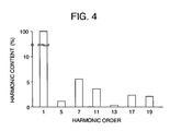
- Fig. 4 shows relative harmonic content of current in the embodiment of the invention.
- applied voltage is adjusted through PWM, so that the resulting harmonic wave becomes one, which high harmonics other than the fundamental wave superpose one another to distort.
- high harmonics having a fifth order, a seventh order, an eleventh order, a thirteenth order, a seventeenth order and a nineteenth order which correspond to five, seven, nine, eleven, thirteen and nineteen times as high as the fundamental wave frequency of a first order, superpose one another.
- the total eddy current loss of the rotor includes added eddy current losses caused by the harmonic components, and amounts even to 5 kW as measured with a rotor having an output of 180 kW, so that it is not possible to realize a very high speed permanent magnet type synchronous motor. That is, loss raises a magnet in temperature to decrease the effective magnetic flux, which will make it impossible to obtain a desired output.
- a permanent magnet shares 10 % of loss caused by harmonic magnetic flux, and the intermediate sleeve 10 shares 90 % thereof.
- the invention provides the electromagnetic steel sheet ring 7 on the outer periphery of the intermediate sleeve 10. Therefore, the harmonic magnetic flux 22 bypasses the electromagnetic steel sheet ring 7 as shown in Fig. 5, which is a view illustrating magnetic flux flow in the permanent magnet type synchronous motor according to the embodiment of the invention, so that no loss is caused in the intermediate sleeve 10, and so loss can be reduced to the sum of loss caused by the permanent magnet 8 and amounting to 10 % of that total loss which would be caused without the electromagnetic steel sheet ring, and loss caused by the electromagnetic steel sheet ring 7 and amounting to several % of the total loss.
- Fig. 5 is a view illustrating magnetic flux flow in the permanent magnet type synchronous motor according to the embodiment of the invention, so that no loss is caused in the intermediate sleeve 10, and so loss can be reduced to the sum of loss caused by the permanent magnet 8 and amounting to 10 % of that total loss which would be caused without the electromagnetic steel sheet ring, and loss caused by the electromagnetic steel sheet ring 7 and amounting
- While loss caused by a rotor relates to efficiency and heat generation of an associated motor, it commands whether a system is established in the case where the present very high speed permanent magnet type synchronous motor is applied to an air compressor.
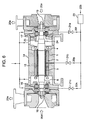
- FIG. 6 shows an air compressor according to an embodiment of the invention.
- An air compressor 14 comprises a shaft 6 supported by magnetic bearings 16, 17 in a frame 15 (indicates an entire storage frame), a rotor 5 (composed of an intermediate sleeve 10, a permanent magnet C, a CFR 9 and a sealing material 11) fitted on the shaft 6, and a stator core 2, on which armature windings 4 are wound.
- an impeller 18 provided at one end of the shaft 6 as a first compression stage compresses air 20d and discharges air 20a.
- Air 20b being a part of the air 20a is cooled by an intermediate cooler 23, the resulting cooled air 20h cooling the magnetic bearing 16 through a valve 21c, the resulting cooled air 20g cooling the permanent magnet type synchronous motor 1 through a valve 21b, and the resulting cooled air 20f cooling the magnetic bearing 17 through a valve 21a, and these all cooled airs are collected and then discharged.
- An impeller 19 provided as a second compression stage compresses air 20e having been compressed by the impeller 18 provided as the first compressor stage (compressed air at the first compressor stage being the sum of the air 20e and the air 20b), and discharges air 20c being an output of the air compressor 14.
- thermal elongation of the shaft 6 on the order of mm is not allowable but limited to the order of ⁇ m since the shaft 6 is supported by the magnetic bearings 16, 17.
- An elongation detecting ring 6 is provided on the shaft 6, and a displacement sensor 25 is used to provide measurement of thermal elongation of the shaft 6, and it has been found that an allowable thermal elongation of the shaft 6 is up to several hundreds of ⁇ m (taking account of vibration damping effects of the magnetic bearings 16, 17).
- Table 1 shows the relationship between relative harmonic content of current and elongation percentage of the shaft in the invention.
- Table 1 shows relative harmonic content of current for A: fifth order component, B: seventh order component, C: eleventh order component, D: thirteenth order component, E: seventeenth order component and F: nineteenth order component with a fundamental wave being 100 %; elongation percentage of the shaft in the respective cases with an allowable elongation percentage of the shaft being 100 %; total relative harmonic contents obtained by calculation with the use of formulae (A 2 + B 2 + C 2 + D 2 + E 2 + F 2 ) 05 ; and judgement of whether A ⁇ B, A ⁇ C ⁇ B and B ⁇ 10% are satisfied, in terms of characters O, X.
- Table 1 shows that the shaft 1 presents an allowable value of at most 100 % for elongation percentage in the case 1, case 2, case 3 and the case 7. From the above condition, it is seen that the total relative harmonic contents of at most 11.19% and A ⁇ B are excluded since they are applicable to the all cases, and A ⁇ C ⁇ B and B ⁇ 10% apply only to the cases 1, 2, 3 and 7.
- the conditions that can realize the air compressor 14 having the very high speed permanent magnet type synchronous motor 1 as a drive source are A ⁇ C ⁇ B and B ⁇ 10 %; and the total content being at most 11%.
- the reactor 13 is adjusted to a value of from 0.2 to 0.1 ⁇ .
- Elongation attributable to centrifugal forces must be taken account when an electromagnetic steel sheet ring is applied to a very high speed permanent magnet type synchronous motor.
- the electromagnetic steel sheet ring 7 is applied to a very high speed permanent magnet type synchronous motor 1 adapted to rotate at speed of at least 40,000 rpm according to the invention, the electromagnetic steel sheet ring 7 itself having tensile strength of at most 55 kg/mm 2 makes the very high speed permanent magnet type synchronous motor unavailable.
- the electromagnet steel sheet ring 7 made of a high tensile strength electromagnetic steel sheet having tensile strength of at least 70 kg/mm 2 makes the very high speed permanent magnet type synchronous motor available.
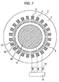
- Fig. 7 is a radial, cross sectional view illustrating a permanent magnet type synchronous motor according to another embodiment of the invention, and the same reference numerals designate the same parts as those shown in Fig. 1.
- the arrangement shown in Fig. 7 is different from that shown in Fig. 1 in that an electromagnetic steel sheet ring 26 is provided on the outer periphery of the shaft 6, and permanent magnets 28 are inserted in a plurality of permanent magnet insertion holes 27 formed in the electromagnetic steel sheet ring 26.
- Table 2 shows the relationship between relative harmonic content of current and elongation percentage of the shaft in the embodiment shown in Table 1. While a stator being the same as that in the table 1 was also used in Table 2, reactance related to a motor constant was different in both. So, a value of an air-core reactor of electric wire was adjusted in value so as to provide reactance, which is equal to that in Table 1.
- Table 2 shows relative harmonic content of current for A: fifth order component, B: seventh order component, C: eleventh order component, D: thirteenth order component, E: seventeenth order component and F: nineteenth order component with a fundamental wave being 100 %; elongation percentage of the shaft in the respective cases with an allowable elongation percentage of the shaft being 100 %; and total relative harmonic contents obtained by calculation with the use of formulae (A 2 + B 2 + C 2 + D 2 + E 2 + F 2 ) 05 .
- Table 2 shows that the shaft presents an allowable value of at most 100 % for elongation percentage in the case 5, case 6, case 7, case 10 and the case 11. From the above condition, it is seen that the above condition cannot be represented in terms of relationships among the respective harmonic orders and the total content of at most 14 % applies to the above cases.
- the condition that can realize the air compressor 14 having the very high speed permanent magnet type synchronous motor 1, in which permanent magnets are embedded into the electromagnetic steel sheet ring, as a drive source is that the total content is at most 14%.
- Table 1 and Table 2 indicate different values for elongation percentage of the shaft is that the electromagnetic steel sheet ring 26 in the arrangement shown in Fig. 7 is located on the surface of the rotor 5 to be cooled by the air 20g. Further, when the electromagnetic steel sheet ring is to be applied to the very high speed permanent magnet type synchronous motor, it is necessary to take account of elongation attributable to centrifugal forces as well as of the arrangement of the permanent magnets.
- the electromagnetic steel sheet ring 26 when the electromagnetic steel sheet ring 26 is applied to a very high speed permanent magnet type synchronous motor 1 adapted to rotate at speed of at least 40,000 rpm according to the invention, the electromagnetic steel sheet ring itself having tensile strength of at most 55 kg/mm 2 makes the very high speed permanent magnet type synchronous motor unavailable.
- the electromagnet steel sheet ring 26 made of a high tensile strength electromagnetic steel sheet having tensile strength of at least 80 kg/mm 2 makes the very high speed permanent magnet type synchronous motor available even without reinforcement with the CFRP 9.
- the invention can provide a high speed permanent magnet type synchronous motor system and an air compressor using the same because harmonic loss of neodymium magnets as well as harmonic loss of the shaft is greatly reduced and loss of the rotor can be reduced to several hundreds of W by interposing a reactor between an inverter and the permanent magnet type synchronous motor, and by adjusting content percentages of harmonic current components supplied to the permanent magnet type synchronous motor from the inverter so that a total content percentage calculated by the formula (A 2 + B 2 + C 2 + D 2 + E 2 + F 2 ) 05 be at most a certain value where A is a content percentage of fifth order component, B is a content percentage of seventh order component, C is a content percentage of eleventh order component, D is a content percentage of thirteenth order component, E is a content percentage of seventeenth order component and F is a content percentage of nineteenth order component in the case of a fundamental wave being 100 %.
Landscapes
- Engineering & Computer Science (AREA)
- Power Engineering (AREA)
- Permanent Field Magnets Of Synchronous Machinery (AREA)
- Iron Core Of Rotating Electric Machines (AREA)
- Control Of Ac Motors In General (AREA)
- Permanent Magnet Type Synchronous Machine (AREA)
Applications Claiming Priority (2)
| Application Number | Priority Date | Filing Date | Title |
|---|---|---|---|
| JP33405099A JP3499786B2 (ja) | 1999-11-25 | 1999-11-25 | 超高速永久磁石式回転電機システム |
| JP33405099 | 1999-11-25 |
Publications (1)
| Publication Number | Publication Date |
|---|---|
| EP1104086A1 true EP1104086A1 (de) | 2001-05-30 |
Family
ID=18272961
Family Applications (1)
| Application Number | Title | Priority Date | Filing Date |
|---|---|---|---|
| EP00118285A Withdrawn EP1104086A1 (de) | 1999-11-25 | 2000-09-05 | Ansteuersystem für eine rotierende elektrische Permanent-Magnet Maschine für sehr hohe Drehzahlen |
Country Status (5)
| Country | Link |
|---|---|
| US (1) | US6441523B1 (de) |
| EP (1) | EP1104086A1 (de) |
| JP (1) | JP3499786B2 (de) |
| KR (1) | KR20010050328A (de) |
| CN (1) | CN1298220A (de) |
Cited By (3)
| Publication number | Priority date | Publication date | Assignee | Title |
|---|---|---|---|---|
| DE102006042041A1 (de) * | 2006-09-07 | 2008-03-27 | Siemens Ag | Verfahren zum Betreiben eines Synchronmotors und entsprechende Spannungsversorgungsvorrichtung |
| WO2012104055A3 (de) * | 2011-01-31 | 2013-01-10 | Ate Antriebstechnik Und Entwicklungs Gmbh | Elektromotor |
| WO2013091736A1 (en) * | 2011-12-23 | 2013-06-27 | L-3 Communications Magnet-Motor Gmbh | Permanent magnet excited electric machine |
Families Citing this family (16)
| Publication number | Priority date | Publication date | Assignee | Title |
|---|---|---|---|---|
| WO2002037649A1 (en) * | 2000-11-02 | 2002-05-10 | Dinyu Qin | Rotor shield for magnetic rotary machine |
| US20020089253A1 (en) * | 2001-01-11 | 2002-07-11 | Kudlacik Henry William | Winding support for use with a superconducting rotor and method for forming the same |
| DE10302164A1 (de) * | 2003-01-22 | 2004-07-29 | Robert Bosch Gmbh | Elektrische Maschine mit Permanentmagnet |
| JP2004245073A (ja) * | 2003-02-12 | 2004-09-02 | Matsushita Electric Ind Co Ltd | 電動圧縮機 |
| US20060214525A1 (en) * | 2004-03-01 | 2006-09-28 | Jansen Ralph H | Magnetic suspension and drive system for rotating equipment |
| US7456537B1 (en) * | 2004-12-17 | 2008-11-25 | The University Of Toledo | Control system for bearingless motor-generator |
| JP2008501080A (ja) * | 2004-05-28 | 2008-01-17 | 松下電器産業株式会社 | 密閉型圧縮機 |
| JP4591112B2 (ja) * | 2005-02-25 | 2010-12-01 | 株式会社日立製作所 | 永久磁石式回転機 |
| US20070138891A1 (en) * | 2005-12-19 | 2007-06-21 | Emerson Electric Co. | Magnet retention and positioning sleeve for surface mounted rotor assemblies |
| US7385328B2 (en) | 2006-05-23 | 2008-06-10 | Reliance Electric Technologies, Llc | Cogging reduction in permanent magnet machines |
| CN101939896B (zh) | 2008-02-07 | 2013-06-05 | 株式会社美姿把 | 无刷电动机 |
| JP4685946B2 (ja) * | 2009-02-18 | 2011-05-18 | 三菱電機株式会社 | 永久磁石型回転電機の回転子およびその製造方法 |
| US8633627B2 (en) * | 2011-08-30 | 2014-01-21 | General Electric Company | Electric machine |
| JP5689550B2 (ja) * | 2013-04-03 | 2015-03-25 | ファナック株式会社 | 回転電機の回転軸部に固定される回転子部材、回転子部材を備える回転子、および回転電機、ならびに、回転子を製造する方法 |
| CN104124846A (zh) * | 2014-08-13 | 2014-10-29 | 四川埃姆克伺服科技有限公司 | 一种永磁同步电机 |
| JP6527102B2 (ja) * | 2016-04-22 | 2019-06-05 | ファナック株式会社 | 保持部材、これを備える回転電機の回転子、及びそれを備える回転電機 |
Citations (5)
| Publication number | Priority date | Publication date | Assignee | Title |
|---|---|---|---|---|
| US4115726A (en) * | 1977-01-04 | 1978-09-19 | Hewlett-Packard Company | Open-loop electric drive with corrective controller |
| US4623830A (en) * | 1983-07-13 | 1986-11-18 | Bbc Brown, Boveri & Company, Limited | Alternating-current machine drive |
| US5189357A (en) * | 1986-07-22 | 1993-02-23 | Board Of Regents, The University Of Texas System | Method and apparatus for improving performance of AC machines |
| WO1999063654A1 (fr) * | 1998-05-29 | 1999-12-09 | Hitachi, Ltd. | Dispositif de commande de moteur |
| WO2000014864A1 (en) * | 1998-09-04 | 2000-03-16 | Kone Corporation | Method for controlling a current-regulated motor |
Family Cites Families (8)
| Publication number | Priority date | Publication date | Assignee | Title |
|---|---|---|---|---|
| EP0014864A1 (de) | 1979-02-23 | 1980-09-03 | Maschinenfabrik Rieter Ag | Fadenführer für Ringspinn- und Ringzwirnmaschinen |
| JPH0648677Y2 (ja) * | 1989-02-22 | 1994-12-12 | 株式会社安川電機 | 低インダクタンスモータ用リード線 |
| JPH0522994A (ja) * | 1991-07-11 | 1993-01-29 | Mitsubishi Electric Corp | 電動機の可変速運転装置 |
| JPH08196096A (ja) * | 1995-01-13 | 1996-07-30 | Matsushita Electric Ind Co Ltd | インバータ装置 |
| JPH09285088A (ja) * | 1996-04-12 | 1997-10-31 | Hitachi Ltd | 永久磁石回転電機及びそれを用いた電動車両 |
| JPH10243586A (ja) * | 1997-02-27 | 1998-09-11 | Hitachi Ltd | 永久磁石式同期電動機とその回転子 |
| JP3484051B2 (ja) * | 1997-09-10 | 2004-01-06 | 株式会社 日立インダストリイズ | 永久磁石式同期電動機及びその製造方法ならびに永久磁石式同期電動機を備えた遠心圧縮機 |
| JPH11307352A (ja) * | 1998-04-17 | 1999-11-05 | Nkk Corp | 高効率モータ |
-
1999
- 1999-11-25 JP JP33405099A patent/JP3499786B2/ja not_active Expired - Fee Related
-
2000
- 2000-09-01 US US09/654,091 patent/US6441523B1/en not_active Expired - Fee Related
- 2000-09-04 KR KR1020000052083A patent/KR20010050328A/ko not_active Withdrawn
- 2000-09-05 CN CN00126328A patent/CN1298220A/zh active Pending
- 2000-09-05 EP EP00118285A patent/EP1104086A1/de not_active Withdrawn
Patent Citations (6)
| Publication number | Priority date | Publication date | Assignee | Title |
|---|---|---|---|---|
| US4115726A (en) * | 1977-01-04 | 1978-09-19 | Hewlett-Packard Company | Open-loop electric drive with corrective controller |
| US4623830A (en) * | 1983-07-13 | 1986-11-18 | Bbc Brown, Boveri & Company, Limited | Alternating-current machine drive |
| US5189357A (en) * | 1986-07-22 | 1993-02-23 | Board Of Regents, The University Of Texas System | Method and apparatus for improving performance of AC machines |
| WO1999063654A1 (fr) * | 1998-05-29 | 1999-12-09 | Hitachi, Ltd. | Dispositif de commande de moteur |
| JPH11341864A (ja) * | 1998-05-29 | 1999-12-10 | Hitachi Ltd | 回転電機の制御装置 |
| WO2000014864A1 (en) * | 1998-09-04 | 2000-03-16 | Kone Corporation | Method for controlling a current-regulated motor |
Non-Patent Citations (1)
| Title |
|---|
| PATENT ABSTRACTS OF JAPAN vol. 3, no. 2000 30 March 2000 (2000-03-30) * |
Cited By (5)
| Publication number | Priority date | Publication date | Assignee | Title |
|---|---|---|---|---|
| DE102006042041A1 (de) * | 2006-09-07 | 2008-03-27 | Siemens Ag | Verfahren zum Betreiben eines Synchronmotors und entsprechende Spannungsversorgungsvorrichtung |
| WO2012104055A3 (de) * | 2011-01-31 | 2013-01-10 | Ate Antriebstechnik Und Entwicklungs Gmbh | Elektromotor |
| US10819168B2 (en) | 2011-01-31 | 2020-10-27 | Ate Antriebstechnik Und Entwicklungs Gmbh | Electric motor |
| WO2013091736A1 (en) * | 2011-12-23 | 2013-06-27 | L-3 Communications Magnet-Motor Gmbh | Permanent magnet excited electric machine |
| US9806574B2 (en) | 2011-12-23 | 2017-10-31 | L-3 Communications Magnet-Motor Gmbh | Low loss permanent magnet excited electric machine |
Also Published As
| Publication number | Publication date |
|---|---|
| JP2001157491A (ja) | 2001-06-08 |
| JP3499786B2 (ja) | 2004-02-23 |
| KR20010050328A (ko) | 2001-06-15 |
| US6441523B1 (en) | 2002-08-27 |
| CN1298220A (zh) | 2001-06-06 |
Similar Documents
| Publication | Publication Date | Title |
|---|---|---|
| US6441523B1 (en) | Very high permanent magnet type electric rotating machine system | |
| EP0215589B1 (de) | Elektrische Hochgeschwindigkeitsrotationsmaschine | |
| KR100508315B1 (ko) | 개선된 고속 전기 모터 | |
| US6566778B1 (en) | Cage-type induction motor for high rotational speeds | |
| CN1842954A (zh) | 具有径向气隙、横向磁通的马达 | |
| US6369478B1 (en) | Permanent-magnet-type electric rotating machine and air compressor and generator using the same | |
| US6785951B2 (en) | Rotor assembly and method of making | |
| US12136897B2 (en) | Energy efficient motor-generator | |
| JP2001057751A (ja) | 永久磁石式同期電動機及び空気圧縮機 | |
| HU195598B (en) | Auxiliary rotor of permanent magnet for asynchronous motors | |
| US7129611B2 (en) | Method and radial gap machine for high strength undiffused brushless operation | |
| Xing et al. | Study on anti-demagnetization of magnet for high speed permanent magnet machine | |
| EP0456498A2 (de) | Verminderung der Oberwellenverluste in Läufern von dynamoelektrischen Maschinen | |
| Fernando et al. | Torsional shear stress minimization techniques and implications on electromagnetic performance of flux-modulated double rotors | |
| Honda et al. | Using the Halbach magnet array to develop an ultrahigh-speed spindle motor for machine tools | |
| KR20030088414A (ko) | 차량용 교류발전기 | |
| US8810102B2 (en) | Rotor for an electric machine with reduced detent torque | |
| EP4293876A1 (de) | Magnetische zahnraddrehmaschine und stromerzeugungssystem | |
| EP2372106B1 (de) | Turbogenerator | |
| Chalmers et al. | Compact permanent-magnet machines | |
| Erickson | Motor design features for adjustable-frequency drives | |
| US12081106B2 (en) | Bearing cap heat sink system for an electric motor | |
| RU2105405C1 (ru) | Одноименнополюсный индукторный генератор с встроенным силовым выпрямителем | |
| Pauly et al. | Brushless servo drives with permanent magnet motors or squirrel cage induction motors-a comparison | |
| JP2001086677A (ja) | 永久磁石式同期電動機 |
Legal Events
| Date | Code | Title | Description |
|---|---|---|---|
| PUAI | Public reference made under article 153(3) epc to a published international application that has entered the european phase |
Free format text: ORIGINAL CODE: 0009012 |
|
| AK | Designated contracting states |
Kind code of ref document: A1 Designated state(s): DE FR GB SE |
|
| AX | Request for extension of the european patent |
Free format text: AL;LT;LV;MK;RO;SI |
|
| 17P | Request for examination filed |
Effective date: 20011001 |
|
| AKX | Designation fees paid |
Free format text: DE FR GB SE |
|
| STAA | Information on the status of an ep patent application or granted ep patent |
Free format text: STATUS: THE APPLICATION HAS BEEN WITHDRAWN |
|
| 18W | Application withdrawn |
Effective date: 20040223 |