EP1104164A1 - Procédé, dispositif de traitement d'images et programme pour la correction d'erreurs de balayage et système de reconnaissance de textes - Google Patents
Procédé, dispositif de traitement d'images et programme pour la correction d'erreurs de balayage et système de reconnaissance de textes Download PDFInfo
- Publication number
- EP1104164A1 EP1104164A1 EP00124917A EP00124917A EP1104164A1 EP 1104164 A1 EP1104164 A1 EP 1104164A1 EP 00124917 A EP00124917 A EP 00124917A EP 00124917 A EP00124917 A EP 00124917A EP 1104164 A1 EP1104164 A1 EP 1104164A1
- Authority
- EP
- European Patent Office
- Prior art keywords
- scanning
- image
- image data
- original
- resolution
- Prior art date
- Legal status (The legal status is an assumption and is not a legal conclusion. Google has not performed a legal analysis and makes no representation as to the accuracy of the status listed.)
- Withdrawn
Links
Images



Classifications
-
- H—ELECTRICITY
- H04—ELECTRIC COMMUNICATION TECHNIQUE
- H04N—PICTORIAL COMMUNICATION, e.g. TELEVISION
- H04N1/00—Scanning, transmission or reproduction of documents or the like, e.g. facsimile transmission; Details thereof
- H04N1/04—Scanning arrangements, i.e. arrangements for the displacement of active reading or reproducing elements relative to the original or reproducing medium, or vice versa
- H04N1/0402—Scanning different formats; Scanning with different densities of dots per unit length, e.g. different numbers of dots per inch (dpi); Conversion of scanning standards
-
- G—PHYSICS
- G06—COMPUTING OR CALCULATING; COUNTING
- G06V—IMAGE OR VIDEO RECOGNITION OR UNDERSTANDING
- G06V30/00—Character recognition; Recognising digital ink; Document-oriented image-based pattern recognition
- G06V30/10—Character recognition
- G06V30/16—Image preprocessing
- G06V30/166—Normalisation of pattern dimensions
-
- G—PHYSICS
- G06—COMPUTING OR CALCULATING; COUNTING
- G06V—IMAGE OR VIDEO RECOGNITION OR UNDERSTANDING
- G06V30/00—Character recognition; Recognising digital ink; Document-oriented image-based pattern recognition
- G06V30/10—Character recognition
-
- H—ELECTRICITY
- H04—ELECTRIC COMMUNICATION TECHNIQUE
- H04N—PICTORIAL COMMUNICATION, e.g. TELEVISION
- H04N1/00—Scanning, transmission or reproduction of documents or the like, e.g. facsimile transmission; Details thereof
- H04N1/04—Scanning arrangements, i.e. arrangements for the displacement of active reading or reproducing elements relative to the original or reproducing medium, or vice versa
- H04N1/10—Scanning arrangements, i.e. arrangements for the displacement of active reading or reproducing elements relative to the original or reproducing medium, or vice versa using flat picture-bearing surfaces
- H04N1/1013—Scanning arrangements, i.e. arrangements for the displacement of active reading or reproducing elements relative to the original or reproducing medium, or vice versa using flat picture-bearing surfaces with sub-scanning by translatory movement of at least a part of the main-scanning components
-
- H—ELECTRICITY
- H04—ELECTRIC COMMUNICATION TECHNIQUE
- H04N—PICTORIAL COMMUNICATION, e.g. TELEVISION
- H04N1/00—Scanning, transmission or reproduction of documents or the like, e.g. facsimile transmission; Details thereof
- H04N1/04—Scanning arrangements, i.e. arrangements for the displacement of active reading or reproducing elements relative to the original or reproducing medium, or vice versa
- H04N1/19—Scanning arrangements, i.e. arrangements for the displacement of active reading or reproducing elements relative to the original or reproducing medium, or vice versa using multi-element arrays
- H04N1/191—Scanning arrangements, i.e. arrangements for the displacement of active reading or reproducing elements relative to the original or reproducing medium, or vice versa using multi-element arrays the array comprising a one-dimensional [1D] array
- H04N1/192—Simultaneously or substantially simultaneously scanning picture elements on one main scanning line
- H04N1/193—Simultaneously or substantially simultaneously scanning picture elements on one main scanning line using electrically scanned linear arrays, e.g. linear CCD arrays
Definitions
- the invention relates to a method for correcting scanning errors, in which Picture elements of an original one after the other along a scanning direction with a Scanning speed can be sampled.
- image data generated with a scanning resolution in the scanning direction.
- the Original is scanned in a scanning direction that matches the direction of relative movement between template and scanner matches.
- This Scanning direction is also referred to as the main scanning direction.
- the picture elements of a line are either e.g. B. using a line of photodiodes, or also scanned one after the other, e.g. B. using a laser scanner with a rotating polygon mirror.
- Resolution is the number of picture elements per unit length. Internationally, one inch is used as the reference length unit, that is 25.4 mm.
- the resolution used for scanning is when using a Photodiode row in the sub-scanning direction is fixed. In the The main scanning direction depends among other things on the size of the Relative speed between the original and the scanner.
- one is said to perform the procedure suitable data processing system, one to carry out the method suitable program and a text entry system can be specified in who use the method.
- the task related to the procedure is carried out by a procedure with the Claim 1 specified process steps solved. Training are specified in the subclaims.
- the invention is based on the knowledge that in the individual scanning devices a constant scanning speed over the whole to be scanned Image is guaranteed.
- the scanning speeds give way different scanning devices from each other. This is e.g. B. on aging and wear of mechanical components as well as tolerances attributed to the manufacture of the scanning devices.
- the used Methods for processing the image data generated during scanning are however the same. Thus the scanning speed also has a decisive influence on the scanning errors.
- the image data processed so that the image represented by them is compressed in the scanning direction or is stretched.
- the template due to a too high relative speed too quickly scanned between original and scanner, so the picture must be stretched.
- the picture shown must be compressed.
- upsetting or stretching can also be done by inserting lines are deleted or deleted, for example every tenth line is deleted.
- the resolution of the image data displayed image changed.
- the image data remains even unchanged. This is a very easy way to get that on the deviation of the scanning speed from the target scanning speed to eliminate traceable scanning errors.
- the resolution is a parameter which applies to the entire image to be scanned. As a result, only one parameter needs to be be changed to those created during the entire scan Eliminate scanning errors. Changing the resolution value is a very reliable way to remove all aberrations, if the scanning speed during the scanning of the entire image is constant and different only between different scanning devices Has values.
- the correction factor KF in this case is greater than one.
- the correction factor KF is less than one.
- the corrected resolution is thus smaller than the scanning resolution.
- the extent L of the template is, for example, by an operator entered or determined using a suitable method. Be applied Procedure for capturing the length of the entire template or the length a mark placed on the template. An easy way to determine The extension of the template is the extension on hand the extent of the image represented by the image data in the scanning direction to estimate. It is of predetermined dimensions for the template selected the extent that of the extent of the scanned Image deviates least in the scan direction and at scan resolution.
- Scan errors free image data with a method for recognizing characters processed In a development of the method according to the invention Scan errors free image data with a method for recognizing characters processed. When carrying out the recognition process, those to be recognized Characters searched for given length coordinates. At this Continuing education can significantly increase the recognition rate because the used Detection methods sensitive to deviations from the ones to be recognized Characters responding from their given positions. A high detection rate is only guaranteed if the characters to be recognized exactly on their given coordinates are positioned. This can be corrected of scanning errors reach that at a target scanning speed deviating scanning speed.
- the invention also relates to a data processing system for correction of scanning errors, a text capture device and a program for correcting scanning errors.
- a data processing system for correction of scanning errors a text capture device and a program for correcting scanning errors.
- the method according to the invention or its further developments are carried out.
- the program also serves to implement the invention Procedure and its training. Therefore, the above apply technical effects also for the data processing system, the text capture device and the program.
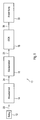
- Figure 1 shows a text capture device 10 for capturing the on a Document 12 shown text.
- the text capture device 10 includes one Scanning unit 14, a device driver 16, a text recognition program 18 and an application program 20.
- the scanning unit 14 is used to scan the document 12, cf. Arrow 22.
- the scanning unit 14 includes a commercially available scanning device, e.g. B. a feed scanner, the document 12 with a resolution of 300 dpi (dots per inch) scans. This means that 300 picture elements, e.g. B. pixels on one Distance of 25.4 mm can be scanned.
- the scanning unit 14 generates a so-called Pixel image in which the picture elements are arranged in a matrix. Image data 24 of the pixel image are sent from the scanning unit 14 to the device driver 16 transferred.
- the device driver 16 contains a program which, from the image data 24 Image file 26 generated.
- the image file 26 contains, in addition to the image data, i.a. Information about the size of the image in the horizontal x-direction and vertical y-direction.
- the device driver 16 is also used to control the scanning unit 14 in response to commands generated by an operator.
- the image file 26 is from Device drivers 16 passed to the text recognition program 18.
- the text recognition program 18 processes the one transferred by the device driver 16 Image file 26 and converts characters in given fields into text strings 28 um. For example, the image of the letter “A” becomes the hexadecimal value "30" is generated, which is assigned to the letter "A". The text characters 28 coded in this way are sent to the application program 20 to hand over.
- the text recognition program 18 is also called “optical character recognition "program, abbreviated OCR program.
- the text data are evaluated by z. B. Transfers are carried out. In doing so, funds are spread across different Accounts posted.
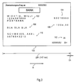
- FIG. 2 shows a template 50 to be scanned, for a transfer form Reading fields 52 to 62.
- Reading fields 52 to 60 contain handwritten information entered, which are required for a transfer form.
- the reading fields 52 to 60 contained in this order information on the transfer recipient, the bank routing number of the transfer recipient, the reason for the transfer, to the transfer amount and to the client of the transfer.
- the value 20 is indicated in a reading field 62. From this
- the text capture program 18 is of value, cf. Figure 1, able to position reading fields 52 to 60 can be read from a table.
- the original 50 has a predetermined length L, in a scanning direction R. for example 145 mm.
- the length L is one for all transfer forms certain type the same.
- FIG. 3 shows the image 100 of a template 50 that is scanned too slowly.
- the picture is 100 in Stretched compared to original 50.
- Image sections 102 to 112 correspond in FIG this order the reading fields 52 to 62. Due to the stretching of the image 100 the positions of the image sections 102 to 112 in the image 100 differ the target positions of the reading fields 52 to 62 in the template 50.
- FIG. 4 shows an image 150 of a template 50 scanned too quickly, cf. Figure 2. Due to the too fast scanning, the image 150 contains fewer picture elements as an image from the original 50 at the target scanning speed has been generated. As a result, the image 150 is compressed in comparison to the original 50.
- the image 150 has a length LB2 in the scanning direction R of, for example, 139 mm.
- Image sections 152 to 162 are images of the reading fields 52 to 62. Because of the the positions of the reading fields 152 to give way to fast scanning 162 in image 150 from the positions specified by reading fields 52 to 62 in the template 50. Images 154, 158 and 162 of the last scanned Reading fields 54, 58 and 62 are considerably closer to the left edge of the picture 150 as the reading fields 54, 58 and 62 on the edge of the template 50. Even with one too fast sampling there is a summation of the sampling errors during the sampling.
- FIG. 5 shows a flow chart with method steps for correcting Sampling errors due to speed deviations during the scanning process are due.
- Figure 5 shows a flow chart with method steps for correcting Sampling errors due to speed deviations during the scanning process are due.
- the method begins in a method step 200.
- the template 50 is from an operator inserted into the feed shaft of the scanning unit 14.
- a subsequent step 202 the operator initiates the retraction template 50 by sending a command to the device driver 16.
- the scanning unit 14 scans the original 50.
- the scanning speed depends on the factory settings of the scanning unit. Moreover the scanning speed changes due to the wear of the scanning unit 14.
- a length of the image generated during scanning is determined. The length is compared to a target length.
- target values for example 135 mm for a first transfer form and 145 mm for the Transfer form specified according to template 50, so a length and thus selected a template that deviates the least from the determined length. In the exemplary embodiment, this is template 50.
- a subsequent method step 206 it is checked whether an original in the Method step 204 could be determined. If this is the case, follow immediately after method step 206, a method step 208 a too large deviation from the specified target values in the process step 204 no suitable template can be determined, it follows after Method step 206 immediately a method step to be explained below 212.
- Method step 208 is followed by a method step 210 in which corrected values for the resolution of the image file generated by the device driver 16 26 can be calculated.
- the scanning resolution is the same as in step 208 determined correction factor KF multiplied by the corrected Get value for the resolution.
- This results for the image 100 according to FIG. 3 a corrected resolution of 300 dpi * 1,018 304 dpi.
- Method step 210 is followed by a method step 212.
- the method step 212 is also carried out immediately after method step 206, if no suitable template is determined in method step 204 could.
- the image file 26 is generated using the text recognition program 18 edited. For the resolution of the picture either the value determined in method step 210 is used or the value of the scanning resolution of 300 dpi. By executing in step 210 The recognition rate of the text recognition program 18 can be corrected be increased.
- the method is ended in a method step 214.
- the in the process step 212 recognized characters can now be processed by the application program 20 become.
- the resolution is corrected in the x direction and performed in the y direction.
Landscapes
- Engineering & Computer Science (AREA)
- Multimedia (AREA)
- Computer Vision & Pattern Recognition (AREA)
- Physics & Mathematics (AREA)
- General Physics & Mathematics (AREA)
- Theoretical Computer Science (AREA)
- Signal Processing (AREA)
- Character Input (AREA)
- Facsimile Scanning Arrangements (AREA)
Applications Claiming Priority (2)
| Application Number | Priority Date | Filing Date | Title |
|---|---|---|---|
| DE19956467A DE19956467A1 (de) | 1999-11-24 | 1999-11-24 | Verfahren, Datenverarbeitungsanlage und Programm zum Korrigieren von Abtastfehlern sowie zugehöriges Texterkennungssystem |
| DE19956467 | 1999-11-24 |
Publications (1)
| Publication Number | Publication Date |
|---|---|
| EP1104164A1 true EP1104164A1 (fr) | 2001-05-30 |
Family
ID=7930134
Family Applications (1)
| Application Number | Title | Priority Date | Filing Date |
|---|---|---|---|
| EP00124917A Withdrawn EP1104164A1 (fr) | 1999-11-24 | 2000-11-15 | Procédé, dispositif de traitement d'images et programme pour la correction d'erreurs de balayage et système de reconnaissance de textes |
Country Status (3)
| Country | Link |
|---|---|
| US (1) | US6744937B1 (fr) |
| EP (1) | EP1104164A1 (fr) |
| DE (1) | DE19956467A1 (fr) |
Families Citing this family (1)
| Publication number | Priority date | Publication date | Assignee | Title |
|---|---|---|---|---|
| US8023697B1 (en) | 2011-03-29 | 2011-09-20 | Kaspersky Lab Zao | System and method for identifying spam in rasterized images |
Citations (5)
| Publication number | Priority date | Publication date | Assignee | Title |
|---|---|---|---|---|
| DE2516961A1 (de) * | 1974-04-17 | 1975-10-30 | Optical Scanning Corp | Signalkorrektur bei fehlender geschwindigkeitslinearitaet |
| US5053885A (en) * | 1989-11-30 | 1991-10-01 | Eastman Kodak Company | Copier with auto scaling, auto paper select, and window scaling |
| EP0565335A1 (fr) * | 1992-04-09 | 1993-10-13 | Xerox Corporation | Méthode et appareil pour réduire la distorsion d'image dans un dispositif asynchrone d'analyse d'entrée |
| US5293432A (en) * | 1992-06-30 | 1994-03-08 | Terminal Data Corporation | Document image scanner with variable resolution windows |
| EP0659017A2 (fr) * | 1993-12-15 | 1995-06-21 | Eastman Kodak Company | Caméra électronique portable fournissant à partir d'un ordinateur l'établissement de paramètres optionnels |
Family Cites Families (7)
| Publication number | Priority date | Publication date | Assignee | Title |
|---|---|---|---|---|
| US4370641A (en) * | 1979-08-15 | 1983-01-25 | International Business Machines Corporation | Electronic control system |
| EP0174659B1 (fr) * | 1984-09-12 | 1992-03-04 | Fuji Photo Film Co., Ltd. | Appareil de lecture avec des moyens pour la compensation des fluctations de la vitesse de balayage et méthode d'ajustement du coefficient de correction |
| JP3534128B2 (ja) * | 1995-01-24 | 2004-06-07 | オムロン株式会社 | 書類の上下方向検知方法及び装置 |
| US5578813A (en) * | 1995-03-02 | 1996-11-26 | Allen; Ross R. | Freehand image scanning device which compensates for non-linear movement |
| US5949922A (en) * | 1996-10-14 | 1999-09-07 | Ricoh Company, Ltd. | Image reading apparatus |
| US5999666A (en) * | 1997-09-09 | 1999-12-07 | Gobeli; Garth W. | Device and method for optical scanning of text |
| JPH11215313A (ja) * | 1998-01-26 | 1999-08-06 | Fuji Photo Film Co Ltd | 画像読取方法 |
-
1999
- 1999-11-24 DE DE19956467A patent/DE19956467A1/de not_active Withdrawn
-
2000
- 2000-11-15 EP EP00124917A patent/EP1104164A1/fr not_active Withdrawn
- 2000-11-20 US US09/716,602 patent/US6744937B1/en not_active Expired - Fee Related
Patent Citations (5)
| Publication number | Priority date | Publication date | Assignee | Title |
|---|---|---|---|---|
| DE2516961A1 (de) * | 1974-04-17 | 1975-10-30 | Optical Scanning Corp | Signalkorrektur bei fehlender geschwindigkeitslinearitaet |
| US5053885A (en) * | 1989-11-30 | 1991-10-01 | Eastman Kodak Company | Copier with auto scaling, auto paper select, and window scaling |
| EP0565335A1 (fr) * | 1992-04-09 | 1993-10-13 | Xerox Corporation | Méthode et appareil pour réduire la distorsion d'image dans un dispositif asynchrone d'analyse d'entrée |
| US5293432A (en) * | 1992-06-30 | 1994-03-08 | Terminal Data Corporation | Document image scanner with variable resolution windows |
| EP0659017A2 (fr) * | 1993-12-15 | 1995-06-21 | Eastman Kodak Company | Caméra électronique portable fournissant à partir d'un ordinateur l'établissement de paramètres optionnels |
Also Published As
| Publication number | Publication date |
|---|---|
| US6744937B1 (en) | 2004-06-01 |
| DE19956467A1 (de) | 2001-06-07 |
Similar Documents
| Publication | Publication Date | Title |
|---|---|---|
| DE69421957T2 (de) | Verfahren und Vorrichtung zum Ausgleich von Positionsoffsetfehlern von Druckkopfelementen beim elektronisch gesteuerten Rasterdruck | |
| DE69713941T2 (de) | Bildverarbeitungssystem | |
| DE69025751T2 (de) | Kopierer mit automatischer skalierung, automatischer papierwahl und fensterskalierung | |
| DE2506020C3 (de) | Verfahren zur Auswertung stereoskopischer Bilder und Vorrichtung zur Auswertung derselben | |
| DE69605255T2 (de) | Vorrichtung und Verfahren für die Extraktion von Artikeln eines Dokuments | |
| DE60025580T2 (de) | Verfahren und Drucker mit Substratverschiebungskontrolle | |
| DE3615906A1 (de) | Bildinformationserkennungsgeraet | |
| DE69722605T2 (de) | Verfahren und vorrichtung zur bilderkennung sowie ihre anwendung in einem kopiergerät und einem drucker | |
| DE69615626T2 (de) | Strahlablenkung zur Verbesserung der Auflösung und zur Verringerung des Streifeneffekts in einem Laserdrucker | |
| DE3328215A1 (de) | Verfahren zur korrektur der bildverzerrung bei bildern, die mittels eines bildwiedergabesystems reproduziert werden | |
| DE69311829T2 (de) | Verfahren und Vorrichtung zur Reduzierung von Bildverzerrungen in einem asynchronen Eingangsabtaster | |
| DE69835140T2 (de) | Bildlesegerät und fokussierungseinstellungsverfahren dafür | |
| DE10013344A1 (de) | Verfahren und Vorrichtung zum Führen eines Laserstrahls über ein Objekt | |
| DE112008003863T5 (de) | Verfahren zum Erzeugen eines Antriebsmusters für ein Galvano-Scannersystem | |
| DE69830897T2 (de) | Verfahren und Vorrichtung zum Verschachteln von rasterabgetasteten Zeilen in einem Mehrstrahlen- Laserabbildungsgerät | |
| DE69812490T2 (de) | Korrektur der fehlerhaften Ausrichting eines Abtastkopfes | |
| EP3712670B1 (fr) | Procédé de microscopie à balayage haute résolution | |
| DE19744501A1 (de) | Vorrichtung und Verfahren zur Kompensation von Bildern bei der Erfassung | |
| DE69624044T2 (de) | Serieller Drucker und Druckverfahren | |
| DE2819265A1 (de) | Bildabtastvorrichtung | |
| EP1203486A1 (fr) | Procede d'elimination electronique de la distorsion d'images dans des dispositifs de balayage par laser | |
| DE69820538T2 (de) | Verfahren zur Kantendetektion von einem Druckmedium | |
| DE4105001A1 (de) | Verfahren und einrichtung zur scharfeinstellung eines optischen abbildungs-systems | |
| DE60210717T2 (de) | Bilderzeugungsgerät und -verfahren | |
| DE19956467A1 (de) | Verfahren, Datenverarbeitungsanlage und Programm zum Korrigieren von Abtastfehlern sowie zugehöriges Texterkennungssystem |
Legal Events
| Date | Code | Title | Description |
|---|---|---|---|
| PUAI | Public reference made under article 153(3) epc to a published international application that has entered the european phase |
Free format text: ORIGINAL CODE: 0009012 |
|
| AK | Designated contracting states |
Kind code of ref document: A1 Designated state(s): AT BE CH CY DE DK ES FI FR GB GR IE IT LI LU MC NL PT SE TR |
|
| AX | Request for extension of the european patent |
Free format text: AL;LT;LV;MK;RO;SI |
|
| 17P | Request for examination filed |
Effective date: 20010718 |
|
| AKX | Designation fees paid |
Free format text: AT BE CH CY DE DK ES FI FR GB GR IE IT LI LU MC NL PT SE TR |
|
| RAP1 | Party data changed (applicant data changed or rights of an application transferred) |
Owner name: WINCOR NIXDORF INTERNATIONAL GMBH |
|
| STAA | Information on the status of an ep patent application or granted ep patent |
Free format text: STATUS: THE APPLICATION HAS BEEN WITHDRAWN |
|
| 18W | Application withdrawn |
Effective date: 20060223 |