EP1104176A2 - Réindexation de compression efficace d'images palettisées - Google Patents
Réindexation de compression efficace d'images palettisées Download PDFInfo
- Publication number
- EP1104176A2 EP1104176A2 EP00125444A EP00125444A EP1104176A2 EP 1104176 A2 EP1104176 A2 EP 1104176A2 EP 00125444 A EP00125444 A EP 00125444A EP 00125444 A EP00125444 A EP 00125444A EP 1104176 A2 EP1104176 A2 EP 1104176A2
- Authority
- EP
- European Patent Office
- Prior art keywords
- symbol
- pool
- symbols
- reassignment
- assigned
- Prior art date
- Legal status (The legal status is an assumption and is not a legal conclusion. Google has not performed a legal analysis and makes no representation as to the accuracy of the status listed.)
- Withdrawn
Links
- 238000007906 compression Methods 0.000 title description 22
- 230000006835 compression Effects 0.000 title description 22
- 238000000034 method Methods 0.000 claims abstract description 61
- 238000004364 calculation method Methods 0.000 claims description 4
- 230000001186 cumulative effect Effects 0.000 claims description 4
- 238000013507 mapping Methods 0.000 claims description 3
- 238000004519 manufacturing process Methods 0.000 claims 1
- 230000008569 process Effects 0.000 abstract description 10
- 230000002708 enhancing effect Effects 0.000 abstract 1
- 239000003086 colorant Substances 0.000 description 11
- 238000013459 approach Methods 0.000 description 9
- 230000007704 transition Effects 0.000 description 5
- 230000008859 change Effects 0.000 description 2
- 238000013144 data compression Methods 0.000 description 2
- 230000003247 decreasing effect Effects 0.000 description 2
- 238000010586 diagram Methods 0.000 description 2
- 238000002474 experimental method Methods 0.000 description 2
- 238000013139 quantization Methods 0.000 description 2
- 230000003044 adaptive effect Effects 0.000 description 1
- 230000008901 benefit Effects 0.000 description 1
- 230000005540 biological transmission Effects 0.000 description 1
- 230000001364 causal effect Effects 0.000 description 1
- 230000007423 decrease Effects 0.000 description 1
- 238000013461 design Methods 0.000 description 1
- 238000012986 modification Methods 0.000 description 1
- 230000004048 modification Effects 0.000 description 1
- 238000005457 optimization Methods 0.000 description 1
- 235000013550 pizza Nutrition 0.000 description 1
- 230000008707 rearrangement Effects 0.000 description 1
- 230000011218 segmentation Effects 0.000 description 1
- 238000010187 selection method Methods 0.000 description 1
- 238000012360 testing method Methods 0.000 description 1
- 238000013519 translation Methods 0.000 description 1
- 238000012795 verification Methods 0.000 description 1
Images


Classifications
-
- H—ELECTRICITY
- H04—ELECTRIC COMMUNICATION TECHNIQUE
- H04N—PICTORIAL COMMUNICATION, e.g. TELEVISION
- H04N1/00—Scanning, transmission or reproduction of documents or the like, e.g. facsimile transmission; Details thereof
- H04N1/46—Colour picture communication systems
- H04N1/64—Systems for the transmission or the storage of the colour picture signal; Details therefor, e.g. coding or decoding means therefor
- H04N1/644—Systems for the transmission or the storage of the colour picture signal; Details therefor, e.g. coding or decoding means therefor using a reduced set of representative colours, e.g. each representing a particular range in a colour space
Definitions
- This present invention relates to lossless digital data compression, and more particularly to a method and apparatus for re-indexing digital data to a new symbol mapping as an aid to data compression.
- Color digital images can be represented in a number of digital formats.
- Figure 1 depicts two common formats, a color plane format (planes 24, 26, 28) and a palette-indexed format (table 30 and index image 32).
- digital image 20 is represented by an array of pixel values.
- each pixel is represented in multiple color planes, for instance, red, green, and blue color planes.
- representative color plane values are shown for a subimage 22 of image 20.
- Red color plane 24, green color plane 26, and blue color plane 28 represent the intensity of their respective colors, at each pixel position, as a number between 0 and 255.
- This format allows over sixteen million unique colors to be represented accurately.
- the downside of this format is that it requires twenty-four bits to represent each pixel in the image.
- a typical palette-indexed image has two elements: a palette table, which provides for translation between an index value and its associated red, green, and blue intensity values, and an index image, which contains an index value for each pixel in the image.
- palette table 30 contains eight indices, one for each unique combination of red, green, and blue pixel values that is found in subimage 22. For instance, index 0 represents a light gray, index 1 represents white, and index 2 represents a dark brown.
- Index image 32 contains one index value for each pixel.
- the size of a palette-indexed image is the sum of the sizes of the index image and the palette table.
- the palette table typically requires a relatively negligible amount of space, such that the size of the image is dominated by the size of the index image.
- a viewable image is created from a palette-indexed image by replacing each index with its palette table entry.
- the index "0" for the top left-hand pixel of index image 32 would be used to retrieve the red, green, blue values (192,192,192) from palette table 30 for use during display of that pixel.
- palette-indexed images can greatly benefit if the palette-indexed image data can be compressed, e.g., for efficient storage and/or transmittal. Accordingly, several lossless compression schemes are currently employed with palette-indexed images. It has been recognized that for some lossless compression schemes, compression efficiency can vary with palette selection. In other words, by merely "shuffling" the entries in palette table 30 (and re-indexing the index image to conform to the new palette table), different compression values may result for subsequent compression of the index image.
- Symbol S 1 is then binarized to a second reindex value, selected from all unassigned reindex values, that minimizes the bitwise entropy for the reindexed S 0 and S 1 .
- the process recurses through the remaining symbols S i , each time selecting a reindex value from the unassigned reindex values.
- the Zandi et al. approach is limited to systems that use a binary entropy coder, and the performance of their approach is also limited by the particular order in which symbols are considered for re-indexing.
- the embodiments disclosed herein also overcome prior art limitations regarding symbol selection order. For instance, Zandi et al.'s reindexer considers symbols in a fixed order, essentially answering the question, for each symbol in order, "where should this symbol go?" In contrast, the disclosed embodiments consider a limited number of reassignment positions at each iteration, considering many (or all) unassigned symbols for these positions. In essence, these embodiments answer the question "which symbol best belongs in this position?" This approach avoids situations where a critical symbol (from a compressibility standpoint) receives a suboptimal reassignment, merely because more optimal positions were first filled by less critical symbols.
- a method for reindexing a digital array of symbol values is disclosed.
- the symbols are drawn from an M -ary alphabet of symbols.
- An array of cross-counts is calculated, the array comprising individual cross-counts that each indicate the degree of occurrence, within the digital array, of two symbols drawn from the M -ary alphabet appearing in a predefined contextual relationship.
- a symbol reassignment pool is initialized, and a symbol from the M -ary alphabet is assigned to a seed position in the pool. Unassigned symbols are then considered for assignment to positions adjacent to the symbols already assigned to the pool. To select the appropriate symbol or symbols for assignment, potential functions are calculated for unassigned symbols.
- a potential function for a particular unassigned symbol and pool position is based on weighted cross-counts between that symbol and those symbols already in the pool.
- the unassigned symbol with the largest potential function is assigned to the symbol reassignment pool at the position for which that potential function was calculated.
- each time a symbol is assigned to a position in the symbol reassignment pool potential functions are recalculated, and then another symbol is assigned to a position in the symbol reassignment pool, this process continuing until all symbols from the M -ary alphabet have been assigned to the symbol reassignment pool.
- symbols need not be binary symbols
- the size of the symbol alphabet need not be a power of two
- the pool need not be one-dimensional.
- Figure 2 shows a block diagram of a digital data compressor 60.
- the input to compressor 60 is an image index I and its corresponding palette table T.
- Symbol mapper 62 remaps the symbols in palette table T according to one of the methods described below, producing a new palette table T' .
- Symbol mapper 62 also produces a reassignment table R that indicates which symbol in T corresponds to a given symbol in R .
- reindexer 64 converts the index values in index image I to correspond to new palette table T' , thereby producing new index image I' .
- Palette table T' and index image I' are input to encoder 66, which encodes the table and image, according to known methods, for transmission or storage. Generally, this will involve compressing the index image, and may also involve compressing the palette table.
- the desired function of symbol mapper 62 is to produce a symbol mapping that re-indexes image I to provide optimal compression.
- finding an optimal re-indexing solution by an exhaustive technique is impractical.
- the optimal solution can be obtained by looking at every possible re-indexing map. For example, one potential objective could be to minimize the average difference of the index values of neighboring pixels, i.e., ⁇ u, v Dif( u,v ), where Dif( u,v ) is the sum of the differences of index values between the pixel at location ( u,v ) and its eight neighboring pixels.
- ⁇ u, v Dif( u,v ) is the sum of the differences of index values between the pixel at location ( u,v ) and its eight neighboring pixels.
- the disclosed embodiments present greedy sub-optimal solutions that are simple to implement.
- one good re-indexing criterion is to minimize the average difference of the index values of neighboring pixels.
- the relative index values for neighboring pixels generally matter most.
- the larger the difference between neighboring index values the more bits it takes to code the transition from one pixel to its neighbor.
- the disclosed embodiments are designed to re-index the image such that the average difference of the index values of pixels around transitions between differently-indexed regions is minimized.
- a one-to-one symbol reassignment table maps each symbol S i to a new index value that also takes one integer value in the range [0, M -1].
- one symbol at a time is reassigned in a greedy fashion. Each reassignment is optimized based on the statistics collected from the original index image and previously executed reassignments.
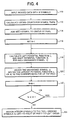
- Figure 3 illustrates one method of arriving at a symbol reassignment table.
- An alphabet 100 of symbols S 0 , S 1 ,..., S 7 is considered for reassignment to positions in a symbol reassignment pool 102, which in this instance is initialized to have fifteen unassigned locations.
- a first symbol (in this case S 2 ) is selected as a seed symbol according to some criterion, and assigned to a seed position 104 in symbol reassignment pool 102.
- another symbol is selected for assignment to either the immediate left or the immediate right of seed position 104.
- the remaining unassigned symbols are then considered for assignment to either the immediate left or the immediate right of these two symbols in the pool, and one symbol is selected for one of these locations.
- the seed position 104 is located in the middle of pool 102, and the size of pool 102 is chosen as 2 M -1. This allows enough space for all symbols to be assigned either to the left or to the right of the seed, in the unlikely event that this should occur.
- an original index image with M symbols is input.
- statistics are gathered from the original index image and stored into a cross-count array.
- Each element of the cross-count array indicates the degree of occurrence of cross-counts C ( S i , S j ) between two different symbols S i and S j .
- the cross-count C ( S i , S j ) is defined as the number of times that a pixel with symbol S i is spatially adjacent to a pixel with symbol S j in the original index image.
- a seed symbol is selected at block 114.
- the seed is selected by first calculating the cumulative cross-counts for each unassigned symbol U i . Then, the symbol that has the largest cumulative cross-counts C i is located, designated as assigned symbol A 0 , and assigned to a seed position in a pool P .
- the size of pool P is defined as N , and N is set to 1 at block 116.
- Subsequent new pool entries can enter P only at either its left or right end.
- potential functions are calculated for the unassigned symbols.
- the left end position of the pool P is considered.
- w ( N,j ) will depend on the physical distance between the currently open left end position of the pool P and the position of an assigned symbol A j .
- the parameter N indicates that the weight w ( N,j ) , in general, may change after each iteration.
- a similar potential function R i is calculated for the right end position and each unassigned symbol U i .
- an unassigned symbol is selected for assignment to the pool based on the potential functions L i and R i .
- the selector identifies the unassigned symbol having the largest potential function. When this largest potential function is a left potential function, this symbol is assigned to the left end position. Otherwise, this symbol is assigned to the right end position.
- the pool size N is incremented at block 122.
- N is compared to M . If N is less than M , unassigned symbols remain, and the process branches to block 118 and iterates. Once a symbol enters the pool P , it will be indicated as assigned, and will no longer be considered for reassignment.
- a symbol reassignment table is created at block 126.
- This table assigns symbols R i , e.g., integers 0,1, ..., M -1, to the spatially-ordered symbols in the pool P in left-to-right or right-to-left order.
- a re-indexed index image is generated by replacing the original index value I(x,y) of each pixel in the index image with the new index value R i that is assigned to that index value.
- the weight w ( N,j ) will generally depend on the position of an assigned symbol A j with respect to the pool end position under consideration.
- One particular choice of the weight w ( N,j ) may be better for a specific subsequent lossless coding scheme than for others.
- one reasonable choice of w ( N,j ) is 1/d(N,j), where d (N,j) is the physical distance between the position of A j and the end position. It will be shown in the following that this is a justifiable, perhaps near optimal choice if LOCO-I/JPEG-LS, the new ISO standard for lossless and near-lossless compression, is to be used to code the index image losslessly.
- LOCO-I low complexity lossless compression for images
- the algorithm is based on a simple fixed-context model that is tuned for efficient performance in conjunction with a collection of context-conditioned Huffinan codes, which is realized with an adaptive symbol-wise, Golomb-Rice code. It follows a traditional predictor-modeler-coder structure.
- the prediction and modeling in LOCO-I are based on the causal template depicted in Figure 5, where x denotes the current pixel, and a, b, c are neighboring pixels in the relative positions shown in the figure.
- the LOCO-I predictor predicts x to be ⁇ :
- the prediction error is, in general, the difference between the current pixel index value and one of its neighbors.
- a Golomb-Rice code G m is used in LOCO-I to encode the residue error within each context.
- the Golomb-Rice code G m encodes an integer n in two parts: a binary representation of n mod m, and a unary representation of ⁇ n/m ⁇ .
- the parameter m is often chosen to be 2 k , for the purpose of simple encoding/decoding procedures. In this case, the length of encoding each symbol is k +1+ ⁇ n /2 k ⁇ . There is an optimal value of k that yields the shortest possible average code length for an input distribution.
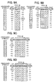
- Figure 6 represents the index values for an index image 34 taken from a small section of a computer desktop icon.
- Image 34 contains twelve different indices 0-11, which were assigned left-to-right, top-to-bottom as new colors were encountered in a scan of the icon.
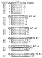
- Figure 7 shows a cross-count array 36 for index image 34.
- the twelve indices appear across the top and down the left side of the array.
- Index image 34 is scanned, and the array position corresponding to two indices is incremented each time the two indices appear horizontally adjacent each other.
- the blank locations in array 36 indicate that the two symbols corresponding to that array element never appeared next to each other in the defined context. This indicates that compression performance would probably not be affected by placing those two symbols far apart in symbol space.
- vertically-adjacent, diagonally-adjacent, or other pixel relationships could also be represented in cross-count array 36.
- Figures 9A through 9J illustrate, step-by-step, how each symbol appearing in index image 34 was assigned to a pool 50 in order to produce (for illustration purposes) the rearranged cross-count array 38 of Figure 8.
- first and second (unillustrated) steps the following happens:
- the cumulative cross-counts for each symbol are tallied, resulting in symbol 5 being selected as a seed symbol.
- a first iteration of the selection procedure selects symbol 1 for assignment adjacent symbol 5, as symbol 1 has the highest number of cross-counts with symbol 5.
- Symbol I is arbitrarily assigned to the right of symbol 5 in pool 50.
- Figure 9A illustrates the second iteration of the procedure, after symbols 1 and 5 are assigned to pool 50.
- the values under the entries of pool 50 illustrate the cross-counts between each assigned and each unassigned symbol. From these, distance-weighted left and right scores are calculated for each unassigned symbol. Because the weighting function is inversely proportional to pool distance, the scoring is relatively simple for this iteration ⁇ a left score for an unassigned symbol is its cross-count with symbol 5, added to half its cross-count for symbol 1. Using this function, the right score for unassigned symbol 6 is the largest score overall, and thus symbol 6 is assigned to the right end of pool 50, as shown in Figure 9B.
- a seed symbol can be chosen as in the first embodiment.
- a new ordered pair ( U i , U k ) ( i ⁇ k ) of unassigned symbols is to be assigned to the left and/or right hand sides of the current pool P .
- Case 1 ⁇ P ⁇ U i U k
- Case 2 U i U k ⁇ P ⁇
- Case 3 U i ⁇ P ⁇ U k .
- w R( N,j ) and w L( N,j ) represent the weights corresponding to the cases where the symbol is assigned to the right hand or the left hand sides of the pool, respectively
- the case with the largest potential function value is chosen.
- the corresponding largest potential function value is recorded as the potential value for that pair.
- the ordered pair that has the largest potential value is selected for reassignment at this iteration, and is assigned according to the best scenario among the three cases.
- the first half of potential function D j is the same for different k values.
- This intermediate result can be calculated once for each i and stored for later usage. It can also be used for similar terms calculated for the ordered pair ( U k , U i ), and will differ by only one added element for the second half of D 3 .
- Some intermediate results generated in previous iterations can also be stored and used in later iterations. For example, if for the current iteration a pair of symbols are chosen to join the pool from the right hand side (Case 1), then some intermediate results obtained for Case 2 in the current iteration can be reused for the next iteration, since the pool configuration does not change except that there are two more symbols at the right hand side of the pool.
- the same idea is also applicable to the basic scheme where only one symbol is assigned at one time.
- weighting function cannot be expressed exponentially, it is usually possible to avoid most of the exact weighting function calculations at each iteration. This can be accomplished by use of a simple but approximate potential function that is strictly greater than or equal to the actual potential weighting function.
- the approximate potential function can be used as follows. Suppose that the last iteration resulted in the assignment of a symbol to the left side of the pool. The right potential functions for the remaining unassigned symbols can be updated by adding a single cross-count to each for the newly assigned symbol, as has been previously described. The left potential functions are updated using the approximate potential weighting function above. During this updating process, the largest potential function found, actual or approximate, is noted. If the largest is an actual potential function, its symbol can be assigned immediately to the appropriate pool position with no further calculation. If the largest is approximate, the corresponding actual potential weighting function is calculated for that symbol. This actual function is compared to the other potential functions ⁇ actual or approximate ⁇ and if one is found that is greater, its corresponding actual potential weighting function is calculated if required. If the actual function for this symbol is still greater than the current maximum, it becomes the new comparison for the remainder of the search.
- This 2D pool allows symbols to have greater adjacency in symbol space. The increased adjacency allows more symbols to be packed adjacent, and is thus useful when symbols occur in many different contexts in an image.
- the disadvantage of this approach is that it requires additional complexity. For instance, pool 52 requires twice as many potential functions, since they must be calculated for positions L 1 , L 2 , R 1 , and R 2 . Pool 52 may also require that one bit plane of the index image, e.g., the most significant bit plane, be coded separately from the other bit planes in order to achieve best results.
- the re-indexing method of the first embodiment was tested on a set of icon-like graphics images. Each image has a limited number of colors. Each image was first palettized, resulting in a color palette table and an index image. The initial indices were generated using a luminance-intensity-based approach. In other words, the colors were sorted according to the intensity value of the luminance component. Then, the indices 0 , ..., M-1 were assigned to the colors in descending order of luminance intensity. This is a reasonable indexing scheme, because it assigns close index values to colors with close luminance intensity values.
- the first embodiment re-indexing method was then applied to the initial index image.
- the context used to create the cross-count array was generated by adding one count for two horizontally-adjacent symbols, and one count for two vertically-adjacent symbols.
- the weighting function 1/ d ( N, Lj ) was used for the results reported below.
- JPEG-LS Lossless and near-lossless coding of continuous tone still images
- ISO/IEC JTC1/SC29 WG1 JPEG/JBIG
- JPEG-2000 Verification Model 3A see D. Taubman, Report on core experiment CodEff22: ( EBCOT : Embedded Block Coding with Optimized Truncation), ISO/IEC JTC1/SC29/WG1 N1020R, Oct. 21, 1998.
- These two cases are referred to as palette-based JPEG-LS and palette-based JPEG 2000, respectively.
- Table I shows the test results.
- the results for palette-based JPEG-2000 reported in Table 1 are the best results among those obtained using the set of wavelet filters provided in JPEG-2000 VM3A software.
- the number of coding bits for palette-based JPEG-LS and palette-based JPEG-2000 is written as a sum of two parts: the first one is the bits for coding the index image; the second one is the size of the color palette table, which is included uncompressed in the compressed bitstream.
- the results in Table I suggest that it may also be advantageous to compress the color palette table in some cases.
- the palette-based JPEG2000 appears to be more sensitive to the indexing scheme.
- the palette-based JPEG-LS generally outperforms the palette-based JPEG2000.
- the mean removed before wavelet transform is 128 (the default value, good for natural images). Better performance is expected if the mean removed is the actual mean of the index image, since this will generally make the lowest band of the wavelet coefficients more symmetric with respect to zero.
- Palette-based JPEG-LS also outperforms GIF, with an average of about 25% bit rate savings. Note that the performance of GIF does not depend on the indexing scheme used.
- the present invention can be applied to compression of other generalized images (1-dimensional, 2D, or more than 2D) that can be characterized as consisting of one index map and one table that specifies what properties each index corresponds to.
- An example is compression of the VQ (Vector quantization) index resulting from a vector quantization operation, where each of the VQ indices corresponds to a vector in a codebook.
- the invention can also be generalized for applications other than compression. In general, for any optimization application that involves a set of indices and a table that specifies what properties each index corresponds to, where it is possible to define an appropriate measure that depends on the index assignment, the disclosed invention is applicable. In this case, the potential function may be different. The basic idea, however, remains the same.
- the index value of the seed symbol A 0 is merely as a reference value.
- Other methods of choosing a seed symbol may also be appropriate. For example, one of the pair of symbols which have the largest cross-count C ( S i , S j ) can be chosen as the starting symbol, and the other symbol of the pair assigned adjacent it in the pool.
Landscapes
- Engineering & Computer Science (AREA)
- Multimedia (AREA)
- Signal Processing (AREA)
- Compression, Expansion, Code Conversion, And Decoders (AREA)
- Color Television Systems (AREA)
- Compression Or Coding Systems Of Tv Signals (AREA)
- Compression Of Band Width Or Redundancy In Fax (AREA)
- Image Analysis (AREA)
Applications Claiming Priority (2)
| Application Number | Priority Date | Filing Date | Title |
|---|---|---|---|
| US448061 | 1995-05-23 | ||
| US09/448,061 US6522783B1 (en) | 1999-11-23 | 1999-11-23 | Re-indexing for efficient compression of palettized images |
Publications (2)
| Publication Number | Publication Date |
|---|---|
| EP1104176A2 true EP1104176A2 (fr) | 2001-05-30 |
| EP1104176A3 EP1104176A3 (fr) | 2004-01-02 |
Family
ID=23778861
Family Applications (1)
| Application Number | Title | Priority Date | Filing Date |
|---|---|---|---|
| EP00125444A Withdrawn EP1104176A3 (fr) | 1999-11-23 | 2000-11-20 | Réindexation de compression efficace d'images palettisées |
Country Status (3)
| Country | Link |
|---|---|
| US (1) | US6522783B1 (fr) |
| EP (1) | EP1104176A3 (fr) |
| JP (1) | JP2001211081A (fr) |
Cited By (5)
| Publication number | Priority date | Publication date | Assignee | Title |
|---|---|---|---|---|
| CN101964188A (zh) * | 2010-04-09 | 2011-02-02 | 华为技术有限公司 | 语音信号编码、解码方法、装置及编解码系统 |
| WO2015143351A1 (fr) * | 2014-03-21 | 2015-09-24 | Futurewei Technologies, Inc. | Procédés de codage de contenu d'écran avancé présentant une table de couleurs améliorée et de codage de carte-index |
| CN106464915A (zh) * | 2014-05-22 | 2017-02-22 | 高通股份有限公司 | 基于调色板的视频译码中的最大调色板参数 |
| US10091512B2 (en) | 2014-05-23 | 2018-10-02 | Futurewei Technologies, Inc. | Advanced screen content coding with improved palette table and index map coding methods |
| US10291827B2 (en) | 2013-11-22 | 2019-05-14 | Futurewei Technologies, Inc. | Advanced screen content coding solution |
Families Citing this family (22)
| Publication number | Priority date | Publication date | Assignee | Title |
|---|---|---|---|---|
| US6983074B1 (en) * | 2000-06-14 | 2006-01-03 | Adobe Systems Incorporated | Data compression system and technique |
| US7443544B2 (en) * | 2000-12-01 | 2008-10-28 | Zoran Corporation | Accelerating color conversion using a temporary palette cache |
| CN1460387A (zh) * | 2001-03-26 | 2003-12-03 | 皇家菲利浦电子有限公司 | 多媒体项的存储 |
| US7164369B2 (en) * | 2001-06-19 | 2007-01-16 | Sharp Laboratories Of America, Inc. | System for improving storage efficiency of digital files |
| US20080123739A1 (en) * | 2003-09-25 | 2008-05-29 | Amimon Ltd. | Wireless Transmission of High Quality Video |
| US7664184B2 (en) * | 2004-07-21 | 2010-02-16 | Amimon Ltd. | Interpolation image compression |
| US7627182B2 (en) * | 2005-12-30 | 2009-12-01 | Intel Corporation | Method and apparatus for varied format encoding and decoding of pixel data |
| US7865025B2 (en) * | 2006-08-01 | 2011-01-04 | Ching-Wei Yeh | Data processing method in embedded block coding with optimized truncation module |
| CN100423082C (zh) * | 2006-11-03 | 2008-10-01 | 北京京东方光电科技有限公司 | 一种平板显示器系统内接口单元 |
| US9106933B1 (en) | 2010-05-18 | 2015-08-11 | Google Inc. | Apparatus and method for encoding video using different second-stage transform |
| US9210442B2 (en) | 2011-01-12 | 2015-12-08 | Google Technology Holdings LLC | Efficient transform unit representation |
| US9380319B2 (en) | 2011-02-04 | 2016-06-28 | Google Technology Holdings LLC | Implicit transform unit representation |
| US9219915B1 (en) | 2013-01-17 | 2015-12-22 | Google Inc. | Selection of transform size in video coding |
| US9967559B1 (en) | 2013-02-11 | 2018-05-08 | Google Llc | Motion vector dependent spatial transformation in video coding |
| US9544597B1 (en) | 2013-02-11 | 2017-01-10 | Google Inc. | Hybrid transform in video encoding and decoding |
| US9674530B1 (en) | 2013-04-30 | 2017-06-06 | Google Inc. | Hybrid transforms in video coding |
| US9565451B1 (en) | 2014-10-31 | 2017-02-07 | Google Inc. | Prediction dependent transform coding |
| US9769499B2 (en) | 2015-08-11 | 2017-09-19 | Google Inc. | Super-transform video coding |
| US10277905B2 (en) | 2015-09-14 | 2019-04-30 | Google Llc | Transform selection for non-baseband signal coding |
| JP6613842B2 (ja) * | 2015-11-24 | 2019-12-04 | 富士通株式会社 | 画像符号化装置、画像符号化方法、及び画像符号化プログラム |
| US9807423B1 (en) | 2015-11-24 | 2017-10-31 | Google Inc. | Hybrid transform scheme for video coding |
| US11122297B2 (en) | 2019-05-03 | 2021-09-14 | Google Llc | Using border-aligned block functions for image compression |
Family Cites Families (8)
| Publication number | Priority date | Publication date | Assignee | Title |
|---|---|---|---|---|
| JP3108479B2 (ja) * | 1991-08-28 | 2000-11-13 | 株式会社リコー | 符号化復号化方法およびその装置 |
| US5471207A (en) | 1994-02-23 | 1995-11-28 | Ricoh Company Ltd. | Compression of palettized images and binarization for bitwise coding of M-ary alphabets therefor |
| JPH08139936A (ja) * | 1994-11-04 | 1996-05-31 | Canon Inc | 符号化方法 |
| US5689589A (en) | 1994-12-01 | 1997-11-18 | Ricoh Company Ltd. | Data compression for palettized video images |
| US5659631A (en) * | 1995-02-21 | 1997-08-19 | Ricoh Company, Ltd. | Data compression for indexed color image data |
| US5930390A (en) * | 1996-03-28 | 1999-07-27 | Intel Corporation | Encoding/decoding signals using a remap table |
| US5990864A (en) * | 1998-01-12 | 1999-11-23 | Autodesk, Inc. | Converting color images to an arbitrary palette |
| US6038346A (en) * | 1998-01-29 | 2000-03-14 | Seiko Espoo Corporation | Runs of adaptive pixel patterns (RAPP) for lossless image compression |
-
1999
- 1999-11-23 US US09/448,061 patent/US6522783B1/en not_active Expired - Lifetime
-
2000
- 2000-11-14 JP JP2000346254A patent/JP2001211081A/ja active Pending
- 2000-11-20 EP EP00125444A patent/EP1104176A3/fr not_active Withdrawn
Non-Patent Citations (1)
| Title |
|---|
| None * |
Cited By (11)
| Publication number | Priority date | Publication date | Assignee | Title |
|---|---|---|---|---|
| CN101964188A (zh) * | 2010-04-09 | 2011-02-02 | 华为技术有限公司 | 语音信号编码、解码方法、装置及编解码系统 |
| CN101964188B (zh) * | 2010-04-09 | 2012-09-05 | 华为技术有限公司 | 语音信号编码、解码方法、装置及编解码系统 |
| US9672830B2 (en) | 2010-04-09 | 2017-06-06 | Huawei Technologies Co., Ltd. | Voice signal encoding and decoding method, device, and codec system |
| US10291827B2 (en) | 2013-11-22 | 2019-05-14 | Futurewei Technologies, Inc. | Advanced screen content coding solution |
| WO2015143351A1 (fr) * | 2014-03-21 | 2015-09-24 | Futurewei Technologies, Inc. | Procédés de codage de contenu d'écran avancé présentant une table de couleurs améliorée et de codage de carte-index |
| CN106030651A (zh) * | 2014-03-21 | 2016-10-12 | 华为技术有限公司 | 利用改进的颜色表和索引图编码方法的高级屏幕内容编码 |
| US10638143B2 (en) | 2014-03-21 | 2020-04-28 | Futurewei Technologies, Inc. | Advanced screen content coding with improved color table and index map coding methods |
| CN106464915A (zh) * | 2014-05-22 | 2017-02-22 | 高通股份有限公司 | 基于调色板的视频译码中的最大调色板参数 |
| CN106464915B (zh) * | 2014-05-22 | 2019-09-03 | 高通股份有限公司 | 基于调色板的视频译码中的最大调色板参数 |
| US10750198B2 (en) | 2014-05-22 | 2020-08-18 | Qualcomm Incorporated | Maximum palette parameters in palette-based video coding |
| US10091512B2 (en) | 2014-05-23 | 2018-10-02 | Futurewei Technologies, Inc. | Advanced screen content coding with improved palette table and index map coding methods |
Also Published As
| Publication number | Publication date |
|---|---|
| EP1104176A3 (fr) | 2004-01-02 |
| US6522783B1 (en) | 2003-02-18 |
| JP2001211081A (ja) | 2001-08-03 |
Similar Documents
| Publication | Publication Date | Title |
|---|---|---|
| US6522783B1 (en) | Re-indexing for efficient compression of palettized images | |
| CN1316812C (zh) | 利用变长色码对调色板处理的彩色图像进行压缩 | |
| US6038346A (en) | Runs of adaptive pixel patterns (RAPP) for lossless image compression | |
| EP1512115B1 (fr) | Intracodage base sur une prediction spatiale | |
| KR100944282B1 (ko) | Golomb-rice 코딩을 사용한 dct 압축 | |
| KR100196271B1 (ko) | 화상부호화복호화 장치 및 방법 | |
| EP0146728B1 (fr) | Système de traitement d'image | |
| US5363219A (en) | Image processing method and apparatus | |
| EP1834487B1 (fr) | Procede de codage entropique ameliore | |
| EP0982949B1 (fr) | Méthode et appareil de traitement d'images | |
| US20080219578A1 (en) | Method and apparatus for context adaptive binary arithmetic coding and decoding | |
| Salomon | Coding for data and computer communications | |
| JP2005516553A (ja) | 複合文書の圧縮のためのコーダに整合したレイヤ分離 | |
| US8810562B2 (en) | Hierarchical lossless compression | |
| KR20040018413A (ko) | 골롬-라이스를 이용하는 무손실의 프레임내 인코딩 | |
| JP4522199B2 (ja) | 画像符号化装置及び画像処理装置及びそれらの制御方法、並びにコンピュータプログラム及びコンピュータ可読記憶媒体 | |
| US6587588B1 (en) | Progressive image decoder for wavelet encoded images in compressed files and method of operation | |
| JP3087835B2 (ja) | 画像符号化方法および装置ならびに画像復号方法および装置 | |
| WO1996017469A1 (fr) | Procedes permettant d'effectuer le codage et le decodage a l'aide de differences maximales de deux dimensions pendant la compression en temps reel d'images de facsimile, et appareil | |
| Memon et al. | Transcoding gif images to jpeg-ls | |
| EP1033885B1 (fr) | Dispositif et procede de codage et de decodage | |
| KR100495001B1 (ko) | 이미지 압축 부호화 방법 및 시스템 | |
| JPH06164941A (ja) | 画像データ符号化方法及び装置 | |
| Neves | Lossless compression of images with specific characteristics | |
| JPH11272843A (ja) | カラー画像の符号化装置およびその方法並びにカラー画像の復号化装置およびその方法 |
Legal Events
| Date | Code | Title | Description |
|---|---|---|---|
| PUAI | Public reference made under article 153(3) epc to a published international application that has entered the european phase |
Free format text: ORIGINAL CODE: 0009012 |
|
| AK | Designated contracting states |
Kind code of ref document: A2 Designated state(s): AT BE CH CY DE DK ES FI FR GB GR IE IT LI LU MC NL PT SE TR |
|
| AX | Request for extension of the european patent |
Free format text: AL;LT;LV;MK;RO;SI |
|
| PUAL | Search report despatched |
Free format text: ORIGINAL CODE: 0009013 |
|
| AK | Designated contracting states |
Kind code of ref document: A3 Designated state(s): AT BE CH CY DE DK ES FI FR GB GR IE IT LI LU MC NL PT SE TR |
|
| AX | Request for extension of the european patent |
Extension state: AL LT LV MK RO SI |
|
| 17P | Request for examination filed |
Effective date: 20040609 |
|
| AKX | Designation fees paid |
Designated state(s): DE FR GB |
|
| 17Q | First examination report despatched |
Effective date: 20070307 |
|
| STAA | Information on the status of an ep patent application or granted ep patent |
Free format text: STATUS: THE APPLICATION IS DEEMED TO BE WITHDRAWN |
|
| 18D | Application deemed to be withdrawn |
Effective date: 20070718 |