EP1104252B1 - Recipient a boire antifuite - Google Patents
Recipient a boire antifuite Download PDFInfo
- Publication number
- EP1104252B1 EP1104252B1 EP99943860A EP99943860A EP1104252B1 EP 1104252 B1 EP1104252 B1 EP 1104252B1 EP 99943860 A EP99943860 A EP 99943860A EP 99943860 A EP99943860 A EP 99943860A EP 1104252 B1 EP1104252 B1 EP 1104252B1
- Authority
- EP
- European Patent Office
- Prior art keywords
- valve
- cap
- opening
- cup
- spout
- Prior art date
- Legal status (The legal status is an assumption and is not a legal conclusion. Google has not performed a legal analysis and makes no representation as to the accuracy of the status listed.)
- Revoked
Links
Images









Classifications
-
- A—HUMAN NECESSITIES
- A47—FURNITURE; DOMESTIC ARTICLES OR APPLIANCES; COFFEE MILLS; SPICE MILLS; SUCTION CLEANERS IN GENERAL
- A47G—HOUSEHOLD OR TABLE EQUIPMENT
- A47G19/00—Table service
- A47G19/22—Drinking vessels or saucers used for table service
- A47G19/2205—Drinking glasses or vessels
- A47G19/2266—Means for facilitating drinking, e.g. for infants or invalids
- A47G19/2272—Means for facilitating drinking, e.g. for infants or invalids from drinking glasses or cups comprising lids or covers
-
- B—PERFORMING OPERATIONS; TRANSPORTING
- B65—CONVEYING; PACKING; STORING; HANDLING THIN OR FILAMENTARY MATERIAL
- B65D—CONTAINERS FOR STORAGE OR TRANSPORT OF ARTICLES OR MATERIALS, e.g. BAGS, BARRELS, BOTTLES, BOXES, CANS, CARTONS, CRATES, DRUMS, JARS, TANKS, HOPPERS, FORWARDING CONTAINERS; ACCESSORIES, CLOSURES, OR FITTINGS THEREFOR; PACKAGING ELEMENTS; PACKAGES
- B65D43/00—Lids or covers for rigid or semi-rigid containers
- B65D43/02—Removable lids or covers
- B65D43/0202—Removable lids or covers without integral tamper element
- B65D43/0225—Removable lids or covers without integral tamper element secured by rotation
- B65D43/0231—Removable lids or covers without integral tamper element secured by rotation only on the outside, or a part turned to the outside, of the mouth of the container
-
- B—PERFORMING OPERATIONS; TRANSPORTING
- B65—CONVEYING; PACKING; STORING; HANDLING THIN OR FILAMENTARY MATERIAL
- B65D—CONTAINERS FOR STORAGE OR TRANSPORT OF ARTICLES OR MATERIALS, e.g. BAGS, BARRELS, BOTTLES, BOXES, CANS, CARTONS, CRATES, DRUMS, JARS, TANKS, HOPPERS, FORWARDING CONTAINERS; ACCESSORIES, CLOSURES, OR FITTINGS THEREFOR; PACKAGING ELEMENTS; PACKAGES
- B65D47/00—Closures with filling and discharging, or with discharging, devices
- B65D47/04—Closures with discharging devices other than pumps
- B65D47/20—Closures with discharging devices other than pumps comprising hand-operated members for controlling discharge
- B65D47/2018—Closures with discharging devices other than pumps comprising hand-operated members for controlling discharge comprising a valve or like element which is opened or closed by deformation of the container or closure
- B65D47/2031—Closures with discharging devices other than pumps comprising hand-operated members for controlling discharge comprising a valve or like element which is opened or closed by deformation of the container or closure the element being formed by a slit, narrow opening or constrictable spout, the size of the outlet passage being able to be varied by increasing or decreasing the pressure
-
- B—PERFORMING OPERATIONS; TRANSPORTING
- B65—CONVEYING; PACKING; STORING; HANDLING THIN OR FILAMENTARY MATERIAL
- B65D—CONTAINERS FOR STORAGE OR TRANSPORT OF ARTICLES OR MATERIALS, e.g. BAGS, BARRELS, BOTTLES, BOXES, CANS, CARTONS, CRATES, DRUMS, JARS, TANKS, HOPPERS, FORWARDING CONTAINERS; ACCESSORIES, CLOSURES, OR FITTINGS THEREFOR; PACKAGING ELEMENTS; PACKAGES
- B65D51/00—Closures not otherwise provided for
- B65D51/16—Closures not otherwise provided for with means for venting air or gas
-
- B—PERFORMING OPERATIONS; TRANSPORTING
- B65—CONVEYING; PACKING; STORING; HANDLING THIN OR FILAMENTARY MATERIAL
- B65D—CONTAINERS FOR STORAGE OR TRANSPORT OF ARTICLES OR MATERIALS, e.g. BAGS, BARRELS, BOTTLES, BOXES, CANS, CARTONS, CRATES, DRUMS, JARS, TANKS, HOPPERS, FORWARDING CONTAINERS; ACCESSORIES, CLOSURES, OR FITTINGS THEREFOR; PACKAGING ELEMENTS; PACKAGES
- B65D51/00—Closures not otherwise provided for
- B65D51/16—Closures not otherwise provided for with means for venting air or gas
- B65D51/1633—Closures not otherwise provided for with means for venting air or gas whereby venting occurs by automatic opening of the closure, container or other element
- B65D51/1644—Closures not otherwise provided for with means for venting air or gas whereby venting occurs by automatic opening of the closure, container or other element the element being a valve
- B65D51/165—Closures not otherwise provided for with means for venting air or gas whereby venting occurs by automatic opening of the closure, container or other element the element being a valve formed by a slit or narrow opening
-
- B—PERFORMING OPERATIONS; TRANSPORTING
- B65—CONVEYING; PACKING; STORING; HANDLING THIN OR FILAMENTARY MATERIAL
- B65D—CONTAINERS FOR STORAGE OR TRANSPORT OF ARTICLES OR MATERIALS, e.g. BAGS, BARRELS, BOTTLES, BOXES, CANS, CARTONS, CRATES, DRUMS, JARS, TANKS, HOPPERS, FORWARDING CONTAINERS; ACCESSORIES, CLOSURES, OR FITTINGS THEREFOR; PACKAGING ELEMENTS; PACKAGES
- B65D2543/00—Lids or covers essentially for box-like containers
- B65D2543/00009—Details of lids or covers for rigid or semi-rigid containers
- B65D2543/00018—Overall construction of the lid
- B65D2543/00046—Drinking-through lids
-
- B—PERFORMING OPERATIONS; TRANSPORTING
- B65—CONVEYING; PACKING; STORING; HANDLING THIN OR FILAMENTARY MATERIAL
- B65D—CONTAINERS FOR STORAGE OR TRANSPORT OF ARTICLES OR MATERIALS, e.g. BAGS, BARRELS, BOTTLES, BOXES, CANS, CARTONS, CRATES, DRUMS, JARS, TANKS, HOPPERS, FORWARDING CONTAINERS; ACCESSORIES, CLOSURES, OR FITTINGS THEREFOR; PACKAGING ELEMENTS; PACKAGES
- B65D2543/00—Lids or covers essentially for box-like containers
- B65D2543/00009—Details of lids or covers for rigid or semi-rigid containers
- B65D2543/00018—Overall construction of the lid
- B65D2543/00064—Shape of the outer periphery
- B65D2543/00074—Shape of the outer periphery curved
- B65D2543/00092—Shape of the outer periphery curved circular
-
- B—PERFORMING OPERATIONS; TRANSPORTING
- B65—CONVEYING; PACKING; STORING; HANDLING THIN OR FILAMENTARY MATERIAL
- B65D—CONTAINERS FOR STORAGE OR TRANSPORT OF ARTICLES OR MATERIALS, e.g. BAGS, BARRELS, BOTTLES, BOXES, CANS, CARTONS, CRATES, DRUMS, JARS, TANKS, HOPPERS, FORWARDING CONTAINERS; ACCESSORIES, CLOSURES, OR FITTINGS THEREFOR; PACKAGING ELEMENTS; PACKAGES
- B65D2543/00—Lids or covers essentially for box-like containers
- B65D2543/00009—Details of lids or covers for rigid or semi-rigid containers
- B65D2543/00018—Overall construction of the lid
- B65D2543/00259—Materials used
- B65D2543/00296—Plastic
-
- B—PERFORMING OPERATIONS; TRANSPORTING
- B65—CONVEYING; PACKING; STORING; HANDLING THIN OR FILAMENTARY MATERIAL
- B65D—CONTAINERS FOR STORAGE OR TRANSPORT OF ARTICLES OR MATERIALS, e.g. BAGS, BARRELS, BOTTLES, BOXES, CANS, CARTONS, CRATES, DRUMS, JARS, TANKS, HOPPERS, FORWARDING CONTAINERS; ACCESSORIES, CLOSURES, OR FITTINGS THEREFOR; PACKAGING ELEMENTS; PACKAGES
- B65D2543/00—Lids or covers essentially for box-like containers
- B65D2543/00009—Details of lids or covers for rigid or semi-rigid containers
- B65D2543/00342—Central part of the lid
- B65D2543/00351—Dome-like
-
- B—PERFORMING OPERATIONS; TRANSPORTING
- B65—CONVEYING; PACKING; STORING; HANDLING THIN OR FILAMENTARY MATERIAL
- B65D—CONTAINERS FOR STORAGE OR TRANSPORT OF ARTICLES OR MATERIALS, e.g. BAGS, BARRELS, BOTTLES, BOXES, CANS, CARTONS, CRATES, DRUMS, JARS, TANKS, HOPPERS, FORWARDING CONTAINERS; ACCESSORIES, CLOSURES, OR FITTINGS THEREFOR; PACKAGING ELEMENTS; PACKAGES
- B65D2543/00—Lids or covers essentially for box-like containers
- B65D2543/00009—Details of lids or covers for rigid or semi-rigid containers
- B65D2543/00444—Contact between the container and the lid
- B65D2543/00481—Contact between the container and the lid on the inside or the outside of the container
- B65D2543/0049—Contact between the container and the lid on the inside or the outside of the container on the inside, or a part turned to the inside of the mouth of the container
- B65D2543/00527—NO contact
-
- B—PERFORMING OPERATIONS; TRANSPORTING
- B65—CONVEYING; PACKING; STORING; HANDLING THIN OR FILAMENTARY MATERIAL
- B65D—CONTAINERS FOR STORAGE OR TRANSPORT OF ARTICLES OR MATERIALS, e.g. BAGS, BARRELS, BOTTLES, BOXES, CANS, CARTONS, CRATES, DRUMS, JARS, TANKS, HOPPERS, FORWARDING CONTAINERS; ACCESSORIES, CLOSURES, OR FITTINGS THEREFOR; PACKAGING ELEMENTS; PACKAGES
- B65D2543/00—Lids or covers essentially for box-like containers
- B65D2543/00009—Details of lids or covers for rigid or semi-rigid containers
- B65D2543/00444—Contact between the container and the lid
- B65D2543/00481—Contact between the container and the lid on the inside or the outside of the container
- B65D2543/00537—Contact between the container and the lid on the inside or the outside of the container on the outside, or a part turned to the outside of the mouth of the container
-
- B—PERFORMING OPERATIONS; TRANSPORTING
- B65—CONVEYING; PACKING; STORING; HANDLING THIN OR FILAMENTARY MATERIAL
- B65D—CONTAINERS FOR STORAGE OR TRANSPORT OF ARTICLES OR MATERIALS, e.g. BAGS, BARRELS, BOTTLES, BOXES, CANS, CARTONS, CRATES, DRUMS, JARS, TANKS, HOPPERS, FORWARDING CONTAINERS; ACCESSORIES, CLOSURES, OR FITTINGS THEREFOR; PACKAGING ELEMENTS; PACKAGES
- B65D2543/00—Lids or covers essentially for box-like containers
- B65D2543/00009—Details of lids or covers for rigid or semi-rigid containers
- B65D2543/00953—Sealing means
- B65D2543/00962—Sealing means inserted
- B65D2543/00972—Collars or rings
Definitions
- the present invention relates to a no-spill cup assembly with an improved valve mechanism to prevent liquid from flowing out of the cup when not desired.
- No-spill cup assemblies are well known in the art (see document US-A-5 706 973). In the past, a variety of such assemblies have been developed and marketed. In general, the goal of a no-spill cup is to provide a construction which minimizes or prevents liquid from emerging out of the cup when liquid flow is not desired, i.e. when the user is not drinking. However, though the assemblies of the prior art are intended to avoid such accidents, their construction is such that they generally do not provide a secure enough protection against undesirable spilling or leakage. Thus, when such cups are inverted, or more significantly, when they are shaken vigorously, liquid will often emerge from them. This can be a particular problem with young children, for whom these cups are usually intended. Accordingly, there is a need in the art for an improved cup assembly for preventing undesired spilling of liquids.
- a no spill drinking apparatus (7) comprising:
- an improved cup construction and valve assembly which provides an extremely secure seal against accidental liquid flow from the cup spout.
- a user places his or her mouth against the spout of the cup assembly to suck liquid out of the cup when desired.
- the act of sucking at the spout of the cup creates negative pressure or a partial vacuum against a valve in the cup spout, causing the valve to begin to invert, or turn inside out, thereby unblocking an opening such as an orifice or slit in the valve.
- the application of negative pressure to the top of the valve causes an opening in a portion of the valve to move up off of the base of a protruding member extending through that opening. Once the opening is unblocked, liquid can flow freely through the valve and spout.
- the valve when not in use, the valve sits in a resting, closed position, with the opening pressed against the center seal-off, thereby sealing off the opening, slit or orifice in the valve assembly.
- the valve in its relaxed state, with no negative pressure applied, the valve sits in a closed position with the fluid opening sealed by the center seal-off.
- the protruding member extends through the opening in a male to female relationship such that the orifice sits tightly on the protruding member against the protruding member's bottom portion and the center seal-off or sealing member's base.
- a dual valve device having an adjacent valve which similarly seals when no negative pressure is applied, thereby blocking off the air vents in the cover of the cup, and further preventing the possibility of fluid flow.
- the closed valve position provides an extremely secure seal against fluid leakage, such that inadvertent spills or even deliberate attempts to force liquid outside of the cup, such as by turning the cup upside down, or shaking the cup, are ineffective.
- the cup assembly allows liquid flow to be regulated between regular or maximum flow and minimal flow levels or rates by rotating the position of a valve assembly in the cap or cover of the cup.
- the valve holder is constructed as a two subunit assembly, with one subassembly holding a valve with a larger slit or orifice for fluid flow than the valve in the second subunit.
- a low-flow valve or a higher flow valve can be positioned in the hole leading to the spout. In this manner, a dual position valve assembly is provided allowing either regular flow or minimal liquid flow conditions.
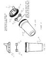
- FIGS 1(a) and 1(b) are a front view and a perspective view, respectively, of an embodiment of the cup assembly, in accordance with the present invention.
- the volume of the cup or liquid holding portion of the assembly can be adjusted as desired.
- a 7 oz. drinking cup is provided, as shown in Figure 1.
- a 9 oz. drinking cup as shown in Figure 2, a 6 1 ⁇ 2 oz. cup, or any other desired size can be provided, as well.
- the sides of the cup can be provided with no handles, one handle, two handles or any other number of handles, for the user's use to grip the cup.
- This handle or handle is preferably sized for a child's hands.
- the outside appearance of the cup and/or the cap can be a solid color, or can be printed with any desired design.
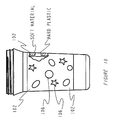
- a no spill cup with a soft gripping area can be provided, as shown in Figure 10.
- a soft ring 102 is provided around the outside of the cup. This ring can be of any width desired, and serves as a finger grip, to make it easier to grasp the cup securely. Preferably, the ring is approximately two inches (2") wide.
- the soft ring 102 has shapes or designs 106 cut out of it, such as stars, ovals, or so forth.
- the hard cup in turn, has raised areas or protuberances corresponding to those shapes or designs. The soft ring fits snugly over these raised areas of the cup, each of the protruding hard shapes fitting into the cutouts of the soft ring, with the surface of the raised areas and the soft ring being flush when the ring is inserted onto the cup.
- the cup is constructed from polycarbonate. In an alternate embodiment, the cup is constructed from polypropylene. If desired, clear polypropylene can be utilized. Alternatively, any other suitable materials can be used for the components of the no-spill cup.
- the components of the cup are all made of durable materials, resistant to breakage, dishwasher safe, and preferably color fast.
- cup 7 includes a no-spill cap or cover 11, a valve holder or assembly 31 and tumbler cup 22.
- No-spill cap 11 includes a spout 14 for drinking liquid from the cup.
- the spout is sized to allow an individual to place his or her mouth over the spout to drink therefrom.
- the spout is sized for the mouth of a child, particularly for a child of a young age.
- No-spill cap 11 forms a cover for placement over tumbler cup 22. When attached to the cup 22, a secure seal is formed such that no liquid can emerge through the connection between the cap 11 and cup 22. In use, cap 11 is sufficiently secured to cup 22 such that shaking the cup assembly, dropping the cup on the floor, or other vigorous movement of the cup assembly, or application of sharp force thereto, is insufficient to separate the cap from the cup.
- no-spill cap 11 and tumbler cup 22 include mating male and female screw threads, such that the cap 11 is a screw-on cap which can be easily rotated onto the tumbler cup 22, as shown in Figure 2.
- a snap-on cap is used, as shown in Figure 1.
- a resilient ring portion of cap 11 securely fits over lip 10 of tumbler cup 22, as is well known in the art.
- a screw-on cap or a snap-on cap are shown as two preferred embodiments, alternatively, any other suitable mechanism to secure the cap to the tumbler cup can be utilized.
- Either the screw-on cap and/or the snap-on cap can be further provided with a gasket 110 between the tumbler cup and the cap, to further seal the connection between the cup and the cap.
- This gasket can be part of the tumbler cup 22 or the cap 11, or can be a separate element inserted between the cap and the cup.
- the gasket 110 is part of cap 11, as shown in Figures 11(a)-(c).
- the cap can be provided with a small annular inner lip, on the inside of the cap, which acts as a gasket.
- This lip as shown in Figures 12(a)-(c), wedges inside the cup when the cap is screwed or placed upon it. The lip acts to further prevent the possibility of liquid flow through the contact between the cup and the cap.
- finger grips are provided on the outside of the cap, such as grooves or the like. These grips facilitate removal and application of the cap, particularly in embodiments requiring the screwing of the cap on and off of the cup.
- the cap is also preferably interchangeable with numerous tumbler cups of different sizes.
- the rim of the tumbler cups are all of the same diameter, although the tumbler cups themselves are of different volumes.
- the same sized cap could be used on a 6 1 ⁇ 2 oz. cup and/or a 7 oz. cup and/or a 9 oz. cup, and so forth.
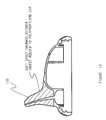
- the cap has a soft spout 130 as shown in Figure 13.
- the spout is made of a thermo-elastimer.
- Spout 130 can be insert molded to a polypropylene cap, providing a combination cap having a hard section for attachment to the cup, and a soft spout portion.
- the spout has a small channel extending therethrough to reduce the liquid volume which can be trapped within the spout portion.
- the cap has a reduced volume spout as shown in Figure 14.
- Reduced volume spout 140 is designed to reduce the volume of liquid which can be trapped within the spout.
- Reduced volume spout 140 has a volume reduction member 144 inserted therein to reduce the internal volume of the spout, and to provide a channel 148 for liquid flow.
- valve assembly subunit 142 extends up into spout 140 to further reduce the amount of liquid which can be trapped in spout 140.
- Valve assembly subunit 142 can, for example, extend into volume reduction member 144. Accordingly, this embodiment reduces the space between the valve and the opening of the drinking spout, to reduce the amount of liquid potentially trapped in this area.
- valve assembly carriers 16 and 18 are tapered holes provided on the underside of the cap.
- Valve assembly carrier or tapered hole 18 leads to an open spout 14, providing a path for liquid flow.
- valve assembly carrier or hole 18 is fully open on both sides, both on its top surface, which leads to spout 14, and on its bottom surface opposite tumbler cup 32, for the flow of liquid out of tumbler cup 22 through hole 18 and through spout 14 into the user's mouth.
- Valve assembly carrier or tapered hole 16 in contrast, provides a passage for the flow of air into the cup during use, allowing liquid to exit through opposing hole 18 and spout 14.
- Hole 16 is open on one side, i.e. on its lower surface opposite tumbler cup 22. On the opposing side, hole 16 merges into the inner surface of cap 11.
- the inner surface of cap 11 is further provided with one or more, preferably small, vents or holes for air flow, allowing air to flow through the vents of cap 11 and through hole 16 into the cup assembly during use.
- no-spill cup 7 further includes valve holder or assembly 31.
- Valve holder 31 is preferably constructed from a high temperature ABS material, and is dimensioned to fit snugly into cap 11.
- valve holder is a separate assembly which fits into cap 11.
- the valve holder can be provided as an integral part of cap 11 and/or cup 7.
- valve holder 31 can be molded as a part of cap 11, such that the valve holder is inseparable from the cap.
- valve holder 31 is a two-subunit assembly connected by bridge 34. Each subunit of the two-subunit assembly is sized to frictionally fit into and be held by either one of tapered holes 16 and 18.
- the spacing between tapered holes 16 and 18 is the same as between the subunits of valve holder 31, such that the valve holder can be easily secured within cap 11.
- the sizing and tapering of holes 16 and 18 and the sizing of valve holder 31 are dimensioned so as to provide a secure, snug mating between the valve assembly and the tapered holes.
- the top of the valve holder (i.e. the side facing the spout) and the bottom of the valve holder (i.e. the side facing the cup) has two different diameters.
- the top is proportioned to fit snugly into the tapered hole, and the bottom is proportioned such that it cannot be inserted into hole 16 or 18. In this way, a mechanism is provided to prevent the valve holder from being inserted into the holes in the wrong orientation, i.e. upside down.
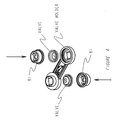
- FIG. 3 is an enlarged, exploded, perspective view of a valve holder useful for understanding the present invention.
- Valve holder 31 consists of two valve holder subunits 37 and 39, connected by a bridge 34. Each valve holder subunit is intended to hold a single valve therein.
- valve or valve member 42 is intended for placement in subunit 37
- valve or valve member 45 is intended for placement in subunit 39.
- Valves 42 and 45 each include a slit or orifice for the passage of liquid. The slit or orifice is preferably through the center portion of the valve, and is dimensioned to allow a predetermined flow level or rate of liquid therethrough, as desired.
- Valve holder subunits 37 and 39 open into sealing units 37a and 39(a) and valve retainers or endcaps 37b and 39(b), respectively.
- subunit 37 is initially in an open position in which the sealing unit and the valve retainer have been pulled or hinged apart.
- the sealing unit and the valve retainer have a tab 60 connecting them, to prevent the components from being permanently separated accidentally.
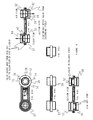
- the valve retainer can be welded into place (e.g. by sonic welding), as shown in Figures 4 and 7.
- the sealing units each have at least one open section 58, such that, in the valve assembly's disassembled state, fluid can pass, unobstructed, through the sealing unit since no valve is in place.
- the valve retainers are open on both sides for unobstructed passage of fluid through the valve retainer in the disassembled state when no valve is in place.
- valve 42 is inserted into the valve holder by placement of the valve between sealing unit 37a and valve retainer 37b.
- the valve retainers can each be folded or hinged back about tab 60, over the sealing unit 37 (or under sealing unit 39, in the orientation shown in the figure) and snapped into place to close the subunits, as shown in Figure 5.
- the resilience of the sealing unit allows for a tight seal to be established between the valve retainer and the sealing unit.
- each subunit secures or encapsulates a valve tightly therein, maintaining the valve in place in the valve holder.
- subunit 37 is the subunit intended for initial placement into hole 18.
- valve 42 upon closing a subunit (e.g. subunit 37 in Figure 3), valve 42 sits securely against center seal-off stop or center stop 52 in sealing unit 37a, with the opening 70 in valve 42 being flush against center seal-off stop 52.
- Valve 42 includes a top, proximal side which will face the spout of the cap, and a distal side which rests against the center seal-off stop when the valve is placed in valve holder 31.
- Center stop 52 functions as a sealing member or blocking element of the valve assembly which seals off and blocks the flow of fluid through the valve.
- center stop 52 consists of a solid substantially flat central area or portion 56 which is impenetrable to the flow of liquid therethrough.
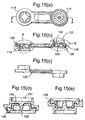
- center stop or seal off 101 is provided with a protruding member 108 extending off of the base of the center seal off, as shown in Figure 15.
- a peripheral area or region 58 can be provided having open areas such as slots or so forth, for allowing the passage of liquid therethrough, as shown, for example in Figure 8(a).
- Central area 56 or center stop 52 can further include stems 74.
- stems 74 can further be reinforced with braces 72, which are reinforcing elements, which provide additional material strength to the connection between the stems and the valve holder.
- valve 42 When in the normal resting position, valve 42 relaxes to sit securely against the center stop 52, as shown in Figure 8(d). In this resting position, opening or orifice 70 of valve 42 presses firmly against the central area 56 of center stop 52, preventing any fluid flow through the valve, and maintaining the valve in a closed configuration. In an embodiment of the present invention, the orifice can sit firmly against and upon a protruding member 108, as shown in Figure 15.
- valve 42 is constructed of a flexible material which is designed to fully invert and turn inside out, or to begin to invert and turn inside out, upon creation of a partial vacuum against the top of the valve 42, as shown in Figure 8(e).
- valve 42 can be a membrane, either in whole or in part.
- the valve is constructed of Kraton or silicone. If silicone is used, a 45 durometer silicone such as Lims 6045 is preferred, which is available from General Electric or from Wacker (a subsidiary of Bayer) of Germany.
- the materials used for the valve assembly and its components are sufficiently durable and heat resistant that the entire valve assembly can be placed in a dishwasher or boiled.
- the valve material is constructed of a single material with a greater thickness of material on the center area which seals off on the center stop, and with a thinner portion of material on the sidewalls. Providing a thinner sidewall portion contributes to the flexibility of the valve at its edges, which further assists and encourages inversion of the valve, by causing the valve to flex at the sidewalls first upon application of negative pressure thereto.
- Preferred dimensions for the valve thickness are approximately 0.4 mm of thickness on the sidewalls and approximately 0.9 mm of thickness on the center area.
- opening or orifice 70 is displaced away from central area 56 of center stop 52.
- the inversion of the valve therefore unblocks opening 70 allowing fluid flow through the subunit.
- negative pressure is being applied to the top of the valve 42 located next to the spout, negative pressure is likewise being applied to the bottom of the adjacent valve in the other subunit, located in the other tapered hole of the cup cover.
- this negative pressure opens the second valve as well, by displacing the opening in the other valve away from its center stop. Inversion of valves 42 allows fluid flow to proceed through both subunits of the assembly.
- Liquid will flow through one subunit of the valve assembly, the subunit connected to the spout, concurrently accompanied by air flow through the other subunit of the assembly, the subunit connected to the air vents. In this manner, liquid smoothly and easily flows though the valve assembly, the spout, and out of the cup.
- valve assembly is provided with a flow bridge 84.
- Flow bridge 84 blocks movement or expansion of the valve 42 beyond a certain maximum distance to prevent the valve from overextending itself, or from being subjected to excessive strain or distension, as shown in Figure 8(e).
- the flow bridge prevents the valve from inverting beyond the point where it can no longer easily revert to its original position.
- the flow bridge provides a shield or a barrier preventing the valve from damage. Thus, it blocks objects such as a spoon or so forth, whether in a dishwasher or otherwise, from easily damaging the valve.
- valve When negative pressure is released or removed from the spout, the valve reverts back to its resting position, and fluid cannot flow through the closed slit or orifice in the valve. In the resting position, no liquid will spill from or emerge out of the cup.
- valve retainer 81 can alternatively be provided.
- valve retainer 94 can be provided as well.
- Valve retainers 81 and 94 serve the same function as valve retainers 37b and 39(b), holding and securing the valve within the valve assembly. It is preferred that the valve retainer, whichever embodiment is utilized, be sonic welded on, to ensure that the valve cannot be dislodged or removed from the holder.
- a system for maintaining a tight seal against fluid flow when the cup is not in use.
- An extremely secure seal is provided, such that excessive or vigorous shaking is ineffective to force fluid out of the cup.
- the valve construction disclosed results in a much tighter seal than that observed in the no-spill cup assemblies of the prior art.
- no liquid will flow through the valve.
- subunits 37 and 39 are preferably identical in all respects excepts for the size of the orifice or slit in valve 42 and the orifice or slit in valve 45. It is preferred that one valve be provided with a larger opening than the other valve, such as a longer slit or larger orifice in one valve than the other. In one embodiment, one valve is provided with an opening in the form of a slit of approximately two hundred thousandths (200/1000) of an inch in length, while the second valve is provided with a slit of approximately fifty thousandths (50/1000) of an inch. Alternatively, other lengths or sizes may, of course, be used as well in accordance with the invention.
- the present inventor has further provided a novel dual acting flow system for regulating fluid flow.
- this system the level of flow of liquid out of the cup during use can be easily regulated. Regulation is accomplished by a simple rotation of the valve assembly which converts the cup between a faster or higher liquid flow, and a slower or lower flow system.
- valve holder 31 can be inserted into cap 11 in either of two configurations.
- valve 45 having a larger opening or orifice or slit, is placed into hole 18, the hole in communication with spout 14.
- a first, higher, flow level of liquid through the valve is established when the user sucks liquid through the spout, due to the use of the valve having the larger opening therein.
- the other valve 42 having the smaller opening, can be inserted into hole 18.
- This valve 42 provides a second, lower flow state, in which liquid can still flow out of the spout, but at a lower flow rate than flow through the first valve. In this way, the rate of flow of liquid out of the cup can be regulated by a parent.
- a two level flow system is disclosed, greater or fewer flow levels can be provided by varying the number of attached subunits having valves therein, or by providing replacement valve holders having different sized openings 70 therein. In all configurations, however, liquid only flows through the valve when the user sucks through the spout, as disclosed above.
- the opening 70 can be, for example, a slit, a slot, an orifice (including any form of hole), or so forth. Likewise, by the term opening, it is contemplated that multiple openings of these or any other types can be provided as well.
- the opening 70 is an "X" shaped slot 78, as shown in Figure 7.
- the opening is a "T" shaped slot 76, as also shown in Figure 7.
- Use of the X-shaped slot 78 shown in Figure 7, will provide a higher flow rate than the T-shaped slot 76 shown therein.
- the flow rate depends on the total length of the slots, or in general, on the size of the opening. Accordingly, both the X-shaped slot and the T-shaped slot can be used in a single valve assembly, each placed in its respective subunit. In this example, a two level flow system is provided, as previously discussed.
- both openings are X-shaped, with one opening larger than the other.
- a 7mm opening (the length from end to end of each crossbar of the "X") can be used for the fast side, and a 6mm opening for the slow side.
- the valve includes a valve member 126 and a center stop or seal off with a protruding member.
- the preferred configurations and dimensions for the valve are shown in Figures 15-17.
- valve member 126 includes an opening such as orifice or hole 118, and is preferably a membrane or flexible portion of material.
- the valve member and, likewise the protruding member, can each be made of a suitable flexible or plastic material, such as silicone, kraton, latex or ABS (Acrylonitrile-Butadiene-Styrene).
- Valve member 126 is preferably encapsulated within an valve assembly subunit 114, 116 or 130, the valve assembly subunit being shown in Figures 15(a) and 16.
- Valve assembly subunit 130 is provided with openings therethrough, for passage of liquid through one side of the subunit, then through the valve, when the valve is in the open position, and then through the other side of the subunit, allowing a user to drink when negative pressure or suction is applied to the valve.
- the valve subunit or another suitable anti-inversion member or flow bridge placed in proximity to the valve member can further serve to block excessive inversion of the valve member.
- the side of the valve subunit or the anti-inversion member is placed at a sufficiently close distance to the valve member such that upon the application of negative pressure or suction to the valve member, the valve member will hit the side of the subunit before fully inverting.
- center stop or sealing member 101 is provided with a protruding member 108 which extends off of a base 104, as shown in Figure 15 (b) and Figures 15(e) - (f).
- Protruding member 108 is a male sealing or protruding member, which in the closed valve state extends through orifice 118.
- a circular or approximately circular orifice is used, although any shaped orifice can be used consistent with the invention.
- male sealing or protruding member 108 is a post or pin, such as a frustoconical or conical post, or a finger-like shaped member.
- Male sealing or protruding member 108 extends off of the base 104 as a protrusion or projection toward the orifice 118.
- sealing or protruding member 108 is tapered.
- the protruding member 108 has a greater diameter at its bottom portion (near the base 104 of the center seal-off), than its diameter at the top.
- base 104 is subtantially flat.
- protruding member 108 is provided opposite female orifice 118, with the protruding member 108 and the orifice 118 in the center seal off forming a male to female mating relationship.
- center seal off 101 presses against orifice 118, with protruding member 108 tightly extending through the orifice and forming a seal against the flow of fluid through the valve.
- the orifice sits snugly against the wider diameter bottom portion of protruding member 108 to form a very tight seal against fluid flow.
- the protruding member 108 extends past the orifice 118, i.e., in the closed valve state, the top of the protruding or sealing member 108 extends both through and past the orifice 118, to further ensure a tight barrier against fluid flow through the valve and to prevent the orifice from overtravelling and moving off of the protruding member.
- the cup with the valve is shaken vigorously no fluid flows therethrough. In fact, shaking the cup can further wedge the protruding member 108 into the orifice 118, further tightening the seal between the protruding member and the edges of the orifice.
- the negative pressure he or she is applying to the top of the valve will open the valve by pulling the valve member containing the opening up and off of the valve and away from the protruding member. Accordingly, with the opening or orifice pulled off of the protruding member, the opening or orifice is unblocked and liquid can flow through the opening into the user's mouth.
- a variable flow valve is provided, such that the harder the user sucks on the spout the greater the flow of liquid that comes out through the valve.
- the valve member preferably rests on a tapered protruding member, such as cone or frusto-conical member, the higher the negative pressure on the top of the valve member, i.e. the more the user sucks on the spout, the more the valve member is pulled off of the cone.
- the opening or orifice in the valve member becomes progressively less blocked by the tapered protruding member 108, revealing a progressively greater cross-sectional area for fluid to flow therethrough.
- the application of negative pressure to the top of the valve causes the valve to partially invert, raising the valve off of the protruding member, but preferably not inverting totally.
- the orifice is raised off of the protruding member, partially unblocking the orifice, which results in fluid flow therethrough as disclosed above.
- the orifice in valve member 124 is circular and approximately 3/32 of an inch in diameter for the slow valve side +/- 1/16 of an inch, and is approximately 1/8 of an inch in diameter for the fast flow valve, also +/-1/16 of an inch.
- the protruding member is provided with a diameter of slightly over an 1/8' at its base, and a diameter of approximately 1/16 of an inch at its top on the fast flow valve, and a diameter of over 3/32 of an inch at its base and approximately 1/32 of an inch at its top on the slower flow valve.
- the opening or hole in the valve member 124 is also preferably radiused on the face, as shown in Figures 17(b) and in the detailed, enlarged view of the orifice in Figure 17(d), to enable the valve member 124 to more easily move up and down the protruding member, and so that it does not stick on the protruding member during operation.
- the radius is 0.0100 inches.
- the valve is part of one or more subunits 114 and/or 116 of a valve assembly 120 for attachment to a no-spill drinking cup, or the cap thereof.
- the valve is an integral part of the cap or cover of the drinking cup.
- the valve holder is molded to the cup cap or cover, or or the cover is molded with the valve inserted therein.
- only a single valve is used, this valve having a protruding member with an approximately seven (7) degree taper.
- two valves are provided, one on each side of the lid or cap of the cup.
- the protruding member on the fast flow side has a taper of approximately seven (7) degrees
- the protruding member on the slow flow side has a taper of approximately nine (9) degrees.
- a single valve is used, this valve having a protruding member with an approximately seven (7) degree taper.
- valve holder be marked to indicate which subunit is suitable for higher flow, and which for lower flow of liquid therethrough.
- the valve holders can be explicitly marked “Fast” and “Slow” as shown in Figures 7 and 9, respectively.
- the subunits or the valve holders can be marked with a hare or rabbit, signifying fast flow, and a tortoise or turtle, signifying slow flow, as respectively also shown in Figures 7 and 9.
- the subunit connected to the spout is, of course, the subunit which controls the liquid flow rate.
- the valve holder can be marked, for example, on the subunit itself, or on the bridge in an area directly adjacent to the subunit, as shown in the figures.
- the valve holder is marked on the top and bottom (i.e. the sides facing the spout and the cup, respectively), such that the symbols and/or words can be seen from the top when the valve holder is being inserted, and from the bottom, once it has already been inserted, to determine which speed valve is in place in the spout.
- the words and/or symbols are only on the bottom of the valve, so that the user can see them from the bottom when inserting the valve holder, and can also view the valve holder from the bottom, once inserted.
Landscapes
- Engineering & Computer Science (AREA)
- Mechanical Engineering (AREA)
- Health & Medical Sciences (AREA)
- General Health & Medical Sciences (AREA)
- Pediatric Medicine (AREA)
- Closures For Containers (AREA)
- Table Devices Or Equipment (AREA)
- Containers And Packaging Bodies Having A Special Means To Remove Contents (AREA)
- Devices For Dispensing Beverages (AREA)
Claims (25)
- Dispositif à boire anti-fuite (7), comprenant:une capsule (11) et un gobelet (22), ladite capsule (11) pouvant être fixée de manière amovible sur ledit gobelet (22)et en être détachée, ladite capsule (11) comprenant un bec souple (14, 130, 140) ;une soupape, ladite soupape comprenant un matériau flexible (126) comportant une ouverture (118), ladite soupape comprenant en outre un élément en saillie (108), ledit élément en saillie (108) s'étendant dans ladite ouverture (118), ladite soupape comportant une position de repos et une position ouverte, un passage du liquide à travers ladite ouverture (118) et à travers ledit bec (14, 130, 140) étant empêché dans ladite position de repos ;un élément de support de la soupape (31), retenant ledit matériau flexible, ledit élément de support de la soupape (31) pouvant être fixé sur ladite capsule (11) et séparé de ladite capsule (11) ; etun évent d'air,le dispositif étant configuré de sorte que l'application d'une pression négative à travers ledit bec (14, 130, 140) entraîne le déplacement dudit matériau flexible (126), ladite ouverture (118) dudit matériau flexible (126) se déplaçant le long dudit élément en saillie (108) en direction dudit bec (14, 130, 140), de sorte que le liquide passe à travers ladite ouverture (118) et hors dudit bec (14, 130, 140), l'air rentrant dans ledit dispositif à travers ledit évent.
- Dispositif selon la revendication 1, dans lequel ledit évent d'air comprend une ouverture, l'ouverture dudit évent d'air étant plus petite que l'ouverture (118) dudit matériau flexible (126) de ladite soupape.
- Dispositif selon l'une quelconque des revendications précédentes, dans lequel ledit bec souple (14, 130, 140) est connecté à une section dure de ladite capsule (11).
- Dispositif selon l'une quelconque des revendications précédentes, dans lequel ledit matériau flexible (126) a la forme d'un bol, ledit bol comportant un rebord et un fond, ledit fond se déplaçant vers ledit rebord et vers ledit bec (14, 130, 140) lors de l'application d'une pression négative à travers ledit bec (14, 130, 140).
- Dispositif selon l'une quelconque des revendications précédentes, dans lequel ladite ouverture dudit évent d'air est fermée avant la consommation et est ouverte au cours de la consommation de liquide à travers ledit bec (14, 130, 140).
- Dispositif selon l'une quelconque des revendications précédentes, dans lequel ladite ouverture (118) est constituée par un trou.
- Dispositif selon l'une quelconque des revendications précédentes, dans lequel ledit matériau flexible (126) a une épaisseur de matériau accrue sur la zone centrale dudit matériau flexible.
- Dispositif selon l'une quelconque des revendications précédentes, dans lequel ladite ouverture dudit évent d'air est constituée par une ouverture dans un matériau flexible.
- Dispositif selon l'une quelconque des revendications précédentes, dans lequel ladite ouverture dudit évent d'air est fermée lorsque ladite ouverture dudit matériau flexible est bloquée, ledit évent d'air étant ouvert lors de l'application d'une pression négative à travers ledit bec (14, 130, 140).
- Dispositif selon l'une quelconque des revendications précédentes, dans lequel ladite ouverture dudit évent d'air est constituée par une ouverture dans un matériau flexible, ladite ouverture dudit évent d'air étant formée dans un matériau flexible (126) séparé dudit matériau flexible que traverse le liquide.
- Dispositif selon l'une quelconque des revendications précédentes, dans lequel ledit dispositif comprend un pont d'écoulement (84), ledit pont d'écoulement établissant une protection empêchant un endommagement dudit matériau flexible.
- Dispositif selon l'une quelconque des revendications précédentes, dans lequel ledit élément de support de la soupape (31) et ladite capsule (11) sont dimensionnés de sorte que ledit élément de support de la soupape (31) est bien ajusté dans ladite capsule (11).
- Dispositif selon l'une quelconque des revendications précédentes, dans lequel ledit élément en saillie (108) a un diamètre supérieur au niveau de sa partie inférieure qu'au niveau de sa partie supérieure.
- Dispositif selon l'une quelconque des revendications précédentes, dans lequel ledit élément en saillie (108) s'étend légèrement à travers ladite ouverture (118).
- Dispositif selon l'une quelconque des revendications précédentes, dans lequel des gobelets de taille différente sont configurés en vue d'une fixation interchangeable sur ladite capsule (11).
- Dispositif selon l'une quelconque des revendications précédentes, dans lequel ladite capsule (11) comporte des filetages de vis, ladite capsule (11) pouvant ainsi être vissée sur le gobelet (22) et dévissée de celui-ci.
- Dispositif selon l'une quelconque des revendications précédentes, dans lequel ledit gobelet (22) est un gobelet dur.
- Dispositif selon la revendication 16, dans lequel ladite capsule (11) comporte en outre des éléments de préhension pour les doigts sur l'extérieur de ladite capsule (11) pour faciliter le vissage de ladite capsule sur ledit gobelet (22) et le dévissage correspondant.
- Dispositif selon l'une quelconque des revendications précédentes, dans lequel le liquide passe à travers ledit élément de support de la soupape (31) lorsqu'un utilisateur boit en se servant dudit bec (14, 130, 140).
- Dispositif selon la revendication 9, dans lequel l'application d'une pression négative entraîne le déplacement d'un matériau flexible afin d'ouvrir ledit évent.
- Dispositif selon l'une quelconque des revendications 1 à 3 ou 5 à 20, dans lequel ledit matériau flexible commence à se retourner lors de ladite application d'une pression négative.
- Dispositif selon l'une quelconque des revendications précédentes, dans lequel ledit dispositif comprend un pont d'écoulement (84), ledit pont d'écoulement étant agencé à proximité du matériau flexible pour empêcher un retournement excessif du matériau flexible.
- Utilisation du dispositif selon l'une quelconque des revendications 1 à 20, sous forme d'un gobelet à boire anti-fuite.
- Utilisation du dispositif selon les revendications 1 à 20, sous forme d'un gobelet à boire anti-fuite pour un enfant.
- Procédé de distribution d'un liquide en utilisant un dispositif à boire anti-fuite (7), le dispositif comprenant :une capsule (11) et un gobelet (22), ladite capsule (11) pouvant être fixée de manière amovible sur ledit gobelet (22)et en être détachée, ladite capsule (11) comprenant un bec souple (14, 130, 140) ;une soupape, ladite soupape comprenant un matériau flexible (126) comportant une ouverture (118), ladite soupape comprenant en outre un élément en saillie (108), ledit élément en saillie (108) s'étendant dans ladite ouverture (118), ladite soupape comportant une position de repos et une position ouverte, un passage du liquide à travers ladite ouverture (118) et à travers ledit bec (14, 130, 140) étant empêché dans ladite position de repos ;un élément de support de la soupape (31), retenant ledit matériau flexible, ledit élément de support de la soupape (31) pouvant être fixé sur ladite capsule (11) et séparé de ladite capsule (11) ;ledit procédé comprenant les étapes ci-dessous :application d'une pression négative à travers ledit bec (14, 130, 140), de sorte que ledit matériau flexible (126) se déplace avec ladite ouverture (118) dudit matériau flexible (126), le long dudit élément en saillie (108), vers ledit bec (14, 130, 140), pour permettre le passage du liquide à travers ladite ouverture (108) et hors dudit bec (14, 130, 140) et pour permettre le passage de l'air dans ledit dispositif (7) à travers ledit évent.
Priority Applications (1)
| Application Number | Priority Date | Filing Date | Title |
|---|---|---|---|
| EP06009518A EP1714592A1 (fr) | 1998-08-21 | 1999-08-20 | Recipient a boire antifuite |
Applications Claiming Priority (5)
| Application Number | Priority Date | Filing Date | Title |
|---|---|---|---|
| US09/138,588 US6321931B1 (en) | 1997-08-21 | 1998-08-21 | No-spill drinking cup apparatus |
| US138588 | 1998-08-21 | ||
| US09/271,779 US6357620B1 (en) | 1997-08-21 | 1999-03-18 | No-spill drinking cup apparatus |
| US271779 | 1999-03-18 | ||
| PCT/US1999/019238 WO2000010434A1 (fr) | 1998-08-21 | 1999-08-20 | Recipient a boire antifuite |
Related Child Applications (1)
| Application Number | Title | Priority Date | Filing Date |
|---|---|---|---|
| EP06009518A Division EP1714592A1 (fr) | 1998-08-21 | 1999-08-20 | Recipient a boire antifuite |
Publications (3)
| Publication Number | Publication Date |
|---|---|
| EP1104252A1 EP1104252A1 (fr) | 2001-06-06 |
| EP1104252A4 EP1104252A4 (fr) | 2002-10-18 |
| EP1104252B1 true EP1104252B1 (fr) | 2006-05-10 |
Family
ID=45582095
Family Applications (2)
| Application Number | Title | Priority Date | Filing Date |
|---|---|---|---|
| EP99943860A Revoked EP1104252B1 (fr) | 1998-08-21 | 1999-08-20 | Recipient a boire antifuite |
| EP06009518A Withdrawn EP1714592A1 (fr) | 1998-08-21 | 1999-08-20 | Recipient a boire antifuite |
Family Applications After (1)
| Application Number | Title | Priority Date | Filing Date |
|---|---|---|---|
| EP06009518A Withdrawn EP1714592A1 (fr) | 1998-08-21 | 1999-08-20 | Recipient a boire antifuite |
Country Status (11)
| Country | Link |
|---|---|
| EP (2) | EP1104252B1 (fr) |
| JP (1) | JP4455761B2 (fr) |
| CN (2) | CN1332860C (fr) |
| AR (1) | AR022980A1 (fr) |
| AT (1) | ATE325565T1 (fr) |
| AU (1) | AU5687499A (fr) |
| BR (1) | BR9906710A (fr) |
| CA (1) | CA2341418C (fr) |
| DE (1) | DE69931264T2 (fr) |
| ES (1) | ES2264825T3 (fr) |
| WO (1) | WO2000010434A1 (fr) |
Families Citing this family (10)
| Publication number | Priority date | Publication date | Assignee | Title |
|---|---|---|---|---|
| MXPA02011943A (es) | 2000-06-01 | 2004-09-06 | Jan Essebaggers | Elemento de flujo con boquilla de succion para recipiente de bebidas carbonatadas que no permite el derrame. |
| US20030029876A1 (en) * | 2000-07-17 | 2003-02-13 | Jean-Pierre Giraud | Dual wall insulated cup assembly and a method of manufacturing an insulated cup assembly |
| AU308823S (en) | 2006-02-13 | 2006-08-16 | Jackel International Ltd | Food serving combination |
| USD557561S1 (en) | 2007-02-13 | 2007-12-18 | The Coca-Cola Company | Double-walled container |
| US10919672B2 (en) * | 2008-03-31 | 2021-02-16 | Angelcare Feeding Usa, Llc | Seal indication mechanism for containers |
| GB0820978D0 (en) * | 2008-11-17 | 2008-12-24 | Reckitt & Colman Overseas | A relief valve |
| DE102011112506A1 (de) * | 2011-09-07 | 2013-03-07 | Feldmann+Schultchen Design Studios Gmbh | Trinkbecherdeckel mit Trinkdurchlass |
| CN105037253A (zh) * | 2015-05-27 | 2015-11-11 | 上海应用技术学院 | 一种超声逼晶法提纯化合物的方法 |
| US9701456B2 (en) * | 2015-09-30 | 2017-07-11 | Dow Global Technologies Llc | Flexible container with extendable spout |
| CN105686537B (zh) * | 2016-03-05 | 2017-06-30 | 中山市美满生活电器有限公司 | 一种智能水壶 |
Family Cites Families (16)
| Publication number | Priority date | Publication date | Assignee | Title |
|---|---|---|---|---|
| FR1191181A (fr) * | 1957-04-17 | 1959-10-16 | Soupape autorégulatrice particulièrement applicable à l'allaitement artificiel etmixte | |
| US3321114A (en) * | 1966-03-04 | 1967-05-23 | Rexall Drug Chemical | Pop-up diaphragm closure |
| US3618825A (en) * | 1969-12-15 | 1971-11-09 | Robert E Clarke | Closure for dispensing spout |
| FR2305361A1 (fr) * | 1975-03-24 | 1976-10-22 | Astra Plastique | Perfectionnements aux dispositifs d'obturation pour bidons, flacons et autres recipients |
| DE2704164A1 (de) * | 1977-02-02 | 1978-08-03 | Bachmann | Druckbetaetigter verschluss fuer tuben und elastische behaeltnisse aller art |
| US4102476A (en) * | 1977-02-22 | 1978-07-25 | Ciba-Geigy Corporation | Squeeze bottle dispenser with air check valve on cover |
| GB1593084A (en) * | 1977-06-24 | 1981-07-15 | Metal Box Co Ltd | Dispensing closures |
| US4836404A (en) * | 1988-02-05 | 1989-06-06 | Peter Coy | Valved container closure |
| DE4027539A1 (de) * | 1990-08-31 | 1992-03-05 | Kautex Werke Gmbh | Quetschflasche mit innenbeutel |
| GB2258860A (en) * | 1991-08-07 | 1993-02-24 | Polytop Plastics | Valved closure |
| US5542670A (en) * | 1995-07-17 | 1996-08-06 | Playtex Products, Inc. | Flow control element and covered drinking cup |
| US5651471A (en) * | 1995-11-03 | 1997-07-29 | Green; Dennis E. | Removable top for drinking bottles |
| US5702025A (en) * | 1996-05-06 | 1997-12-30 | Di Gregorio; Vito | Leak free lid with closure and spout |
| US5706973A (en) * | 1997-01-30 | 1998-01-13 | E. S. Robbins Corporation | Drinking cup and cover with flow control elements |
| NL1005120C2 (nl) * | 1997-01-29 | 1998-07-30 | Ippc International Product Pro | Drinkbeker. |
| ES2292205T3 (es) * | 1997-08-21 | 2008-03-01 | Nouri E. Hakim | Recipiente antiderrame. |
-
1999
- 1999-08-20 BR BR9906710-2A patent/BR9906710A/pt not_active IP Right Cessation
- 1999-08-20 CN CNB2003101029263A patent/CN1332860C/zh not_active Expired - Fee Related
- 1999-08-20 WO PCT/US1999/019238 patent/WO2000010434A1/fr not_active Ceased
- 1999-08-20 ES ES99943860T patent/ES2264825T3/es not_active Expired - Lifetime
- 1999-08-20 JP JP2000565764A patent/JP4455761B2/ja not_active Expired - Fee Related
- 1999-08-20 EP EP99943860A patent/EP1104252B1/fr not_active Revoked
- 1999-08-20 EP EP06009518A patent/EP1714592A1/fr not_active Withdrawn
- 1999-08-20 CN CN99812329A patent/CN1324226A/zh active Pending
- 1999-08-20 CA CA002341418A patent/CA2341418C/fr not_active Expired - Fee Related
- 1999-08-20 DE DE69931264T patent/DE69931264T2/de not_active Expired - Lifetime
- 1999-08-20 AU AU56874/99A patent/AU5687499A/en not_active Abandoned
- 1999-08-20 AT AT99943860T patent/ATE325565T1/de not_active IP Right Cessation
-
2000
- 2000-03-17 AR ARP000101220A patent/AR022980A1/es active IP Right Grant
Also Published As
| Publication number | Publication date |
|---|---|
| WO2000010434A1 (fr) | 2000-03-02 |
| DE69931264T2 (de) | 2007-04-19 |
| EP1714592A1 (fr) | 2006-10-25 |
| CN1515467A (zh) | 2004-07-28 |
| BR9906710A (pt) | 2000-11-14 |
| EP1104252A1 (fr) | 2001-06-06 |
| DE69931264D1 (de) | 2006-06-14 |
| JP2003530271A (ja) | 2003-10-14 |
| AR022980A1 (es) | 2002-09-04 |
| CA2341418A1 (fr) | 2000-03-02 |
| EP1104252A4 (fr) | 2002-10-18 |
| JP4455761B2 (ja) | 2010-04-21 |
| ATE325565T1 (de) | 2006-06-15 |
| CN1324226A (zh) | 2001-11-28 |
| CA2341418C (fr) | 2008-05-20 |
| WO2000010434A9 (fr) | 2005-03-17 |
| ES2264825T3 (es) | 2007-01-16 |
| CN1332860C (zh) | 2007-08-22 |
| AU5687499A (en) | 2000-03-14 |
Similar Documents
| Publication | Publication Date | Title |
|---|---|---|
| US6357620B1 (en) | No-spill drinking cup apparatus | |
| US7789263B2 (en) | No-spill drinking cup apparatus | |
| EP1104252B1 (fr) | Recipient a boire antifuite | |
| CN116588499A (zh) | 容器封闭件、用于容器封闭件的盖元件及容器装置 | |
| JP2003530271A6 (ja) | 漏れなし飲用カップ装置 | |
| AU2004200721B2 (en) | No-spill Drinking Cup Apparatus | |
| EP1880645A2 (fr) | Recipient a boire antifuite | |
| AU2009201922A1 (en) | No-spill drinking cup apparatus | |
| MXPA01001819A (en) | No-spill drinking cup apparatus | |
| JP3223969U (ja) | コップ用キャップ | |
| MXPA00001795A (en) | No-spill drinking cup apparatus |
Legal Events
| Date | Code | Title | Description |
|---|---|---|---|
| PUAI | Public reference made under article 153(3) epc to a published international application that has entered the european phase |
Free format text: ORIGINAL CODE: 0009012 |
|
| 17P | Request for examination filed |
Effective date: 20010321 |
|
| AK | Designated contracting states |
Kind code of ref document: A1 Designated state(s): AT BE CH CY DE DK ES FI FR GB GR IE IT LI LU MC NL PT SE |
|
| AX | Request for extension of the european patent |
Free format text: AL;LT;LV;MK;RO;SI |
|
| A4 | Supplementary search report drawn up and despatched | ||
| AK | Designated contracting states |
Kind code of ref document: A4 Designated state(s): AT BE CH CY DE DK ES FI FR GB GR IE IT LI LU MC NL PT SE |
|
| A4 | Supplementary search report drawn up and despatched |
Effective date: 20021018 |
|
| RIC1 | Information provided on ipc code assigned before grant |
Free format text: 7A 47G 19/22 A |
|
| 17Q | First examination report despatched |
Effective date: 20030205 |
|
| GRAP | Despatch of communication of intention to grant a patent |
Free format text: ORIGINAL CODE: EPIDOSNIGR1 |
|
| GRAS | Grant fee paid |
Free format text: ORIGINAL CODE: EPIDOSNIGR3 |
|
| GRAA | (expected) grant |
Free format text: ORIGINAL CODE: 0009210 |
|
| AK | Designated contracting states |
Kind code of ref document: B1 Designated state(s): AT BE CH CY DE DK ES FI FR GB GR IE IT LI LU MC NL PT SE |
|
| PG25 | Lapsed in a contracting state [announced via postgrant information from national office to epo] |
Ref country code: NL Free format text: LAPSE BECAUSE OF FAILURE TO SUBMIT A TRANSLATION OF THE DESCRIPTION OR TO PAY THE FEE WITHIN THE PRESCRIBED TIME-LIMIT Effective date: 20060510 Ref country code: LI Free format text: LAPSE BECAUSE OF FAILURE TO SUBMIT A TRANSLATION OF THE DESCRIPTION OR TO PAY THE FEE WITHIN THE PRESCRIBED TIME-LIMIT Effective date: 20060510 Ref country code: FI Free format text: LAPSE BECAUSE OF FAILURE TO SUBMIT A TRANSLATION OF THE DESCRIPTION OR TO PAY THE FEE WITHIN THE PRESCRIBED TIME-LIMIT Effective date: 20060510 Ref country code: CH Free format text: LAPSE BECAUSE OF FAILURE TO SUBMIT A TRANSLATION OF THE DESCRIPTION OR TO PAY THE FEE WITHIN THE PRESCRIBED TIME-LIMIT Effective date: 20060510 Ref country code: BE Free format text: LAPSE BECAUSE OF FAILURE TO SUBMIT A TRANSLATION OF THE DESCRIPTION OR TO PAY THE FEE WITHIN THE PRESCRIBED TIME-LIMIT Effective date: 20060510 Ref country code: AT Free format text: LAPSE BECAUSE OF FAILURE TO SUBMIT A TRANSLATION OF THE DESCRIPTION OR TO PAY THE FEE WITHIN THE PRESCRIBED TIME-LIMIT Effective date: 20060510 |
|
| REG | Reference to a national code |
Ref country code: GB Ref legal event code: FG4D |
|
| REG | Reference to a national code |
Ref country code: CH Ref legal event code: EP |
|
| REF | Corresponds to: |
Ref document number: 69931264 Country of ref document: DE Date of ref document: 20060614 Kind code of ref document: P |
|
| REG | Reference to a national code |
Ref country code: IE Ref legal event code: FG4D |
|
| PG25 | Lapsed in a contracting state [announced via postgrant information from national office to epo] |
Ref country code: SE Free format text: LAPSE BECAUSE OF FAILURE TO SUBMIT A TRANSLATION OF THE DESCRIPTION OR TO PAY THE FEE WITHIN THE PRESCRIBED TIME-LIMIT Effective date: 20060810 Ref country code: DK Free format text: LAPSE BECAUSE OF FAILURE TO SUBMIT A TRANSLATION OF THE DESCRIPTION OR TO PAY THE FEE WITHIN THE PRESCRIBED TIME-LIMIT Effective date: 20060810 |
|
| PG25 | Lapsed in a contracting state [announced via postgrant information from national office to epo] |
Ref country code: IE Free format text: LAPSE BECAUSE OF NON-PAYMENT OF DUE FEES Effective date: 20060821 |
|
| PG25 | Lapsed in a contracting state [announced via postgrant information from national office to epo] |
Ref country code: MC Free format text: LAPSE BECAUSE OF NON-PAYMENT OF DUE FEES Effective date: 20060831 |
|
| PG25 | Lapsed in a contracting state [announced via postgrant information from national office to epo] |
Ref country code: PT Free format text: LAPSE BECAUSE OF FAILURE TO SUBMIT A TRANSLATION OF THE DESCRIPTION OR TO PAY THE FEE WITHIN THE PRESCRIBED TIME-LIMIT Effective date: 20061010 |
|
| NLV1 | Nl: lapsed or annulled due to failure to fulfill the requirements of art. 29p and 29m of the patents act | ||
| REG | Reference to a national code |
Ref country code: CH Ref legal event code: PL |
|
| ET | Fr: translation filed | ||
| REG | Reference to a national code |
Ref country code: ES Ref legal event code: FG2A Ref document number: 2264825 Country of ref document: ES Kind code of ref document: T3 |
|
| PLAX | Notice of opposition and request to file observation + time limit sent |
Free format text: ORIGINAL CODE: EPIDOSNOBS2 |
|
| PLBI | Opposition filed |
Free format text: ORIGINAL CODE: 0009260 |
|
| 26 | Opposition filed |
Opponent name: KONINKLIJE PHILIP ELECTRONICS N.V. (NL)/ AVENT LIM Effective date: 20070209 |
|
| PLAF | Information modified related to communication of a notice of opposition and request to file observations + time limit |
Free format text: ORIGINAL CODE: EPIDOSCOBS2 |
|
| PLBB | Reply of patent proprietor to notice(s) of opposition received |
Free format text: ORIGINAL CODE: EPIDOSNOBS3 |
|
| PG25 | Lapsed in a contracting state [announced via postgrant information from national office to epo] |
Ref country code: GR Free format text: LAPSE BECAUSE OF FAILURE TO SUBMIT A TRANSLATION OF THE DESCRIPTION OR TO PAY THE FEE WITHIN THE PRESCRIBED TIME-LIMIT Effective date: 20060811 |
|
| PG25 | Lapsed in a contracting state [announced via postgrant information from national office to epo] |
Ref country code: LU Free format text: LAPSE BECAUSE OF NON-PAYMENT OF DUE FEES Effective date: 20060820 |
|
| PG25 | Lapsed in a contracting state [announced via postgrant information from national office to epo] |
Ref country code: CY Free format text: LAPSE BECAUSE OF FAILURE TO SUBMIT A TRANSLATION OF THE DESCRIPTION OR TO PAY THE FEE WITHIN THE PRESCRIBED TIME-LIMIT Effective date: 20060510 |
|
| APBM | Appeal reference recorded |
Free format text: ORIGINAL CODE: EPIDOSNREFNO |
|
| APBP | Date of receipt of notice of appeal recorded |
Free format text: ORIGINAL CODE: EPIDOSNNOA2O |
|
| APAH | Appeal reference modified |
Free format text: ORIGINAL CODE: EPIDOSCREFNO |
|
| APAW | Appeal reference deleted |
Free format text: ORIGINAL CODE: EPIDOSDREFNO |
|
| APBM | Appeal reference recorded |
Free format text: ORIGINAL CODE: EPIDOSNREFNO |
|
| APBP | Date of receipt of notice of appeal recorded |
Free format text: ORIGINAL CODE: EPIDOSNNOA2O |
|
| APBQ | Date of receipt of statement of grounds of appeal recorded |
Free format text: ORIGINAL CODE: EPIDOSNNOA3O |
|
| PG25 | Lapsed in a contracting state [announced via postgrant information from national office to epo] |
Ref country code: IT Free format text: LAPSE BECAUSE OF NON-PAYMENT OF DUE FEES Effective date: 20090820 |
|
| PGRI | Patent reinstated in contracting state [announced from national office to epo] |
Ref country code: IT Effective date: 20110616 |
|
| REG | Reference to a national code |
Ref country code: DE Ref legal event code: R103 Ref document number: 69931264 Country of ref document: DE Ref country code: DE Ref legal event code: R064 Ref document number: 69931264 Country of ref document: DE |
|
| APBU | Appeal procedure closed |
Free format text: ORIGINAL CODE: EPIDOSNNOA9O |
|
| RDAF | Communication despatched that patent is revoked |
Free format text: ORIGINAL CODE: EPIDOSNREV1 |
|
| RDAG | Patent revoked |
Free format text: ORIGINAL CODE: 0009271 |
|
| STAA | Information on the status of an ep patent application or granted ep patent |
Free format text: STATUS: PATENT REVOKED |
|
| PGFP | Annual fee paid to national office [announced via postgrant information from national office to epo] |
Ref country code: GB Payment date: 20120829 Year of fee payment: 14 |
|
| 27W | Patent revoked |
Effective date: 20120705 |
|
| GBPR | Gb: patent revoked under art. 102 of the ep convention designating the uk as contracting state |
Effective date: 20120705 |
|
| PGFP | Annual fee paid to national office [announced via postgrant information from national office to epo] |
Ref country code: ES Payment date: 20120904 Year of fee payment: 14 Ref country code: FR Payment date: 20120919 Year of fee payment: 14 Ref country code: IT Payment date: 20120831 Year of fee payment: 14 Ref country code: DE Payment date: 20120827 Year of fee payment: 14 |
|
| REG | Reference to a national code |
Ref country code: DE Ref legal event code: R107 Ref document number: 69931264 Country of ref document: DE Effective date: 20130207 |