EP1104712A2 - Gangwahleinrichtung für ein Schaltgetriebe - Google Patents
Gangwahleinrichtung für ein Schaltgetriebe Download PDFInfo
- Publication number
- EP1104712A2 EP1104712A2 EP00124010A EP00124010A EP1104712A2 EP 1104712 A2 EP1104712 A2 EP 1104712A2 EP 00124010 A EP00124010 A EP 00124010A EP 00124010 A EP00124010 A EP 00124010A EP 1104712 A2 EP1104712 A2 EP 1104712A2
- Authority
- EP
- European Patent Office
- Prior art keywords
- input shaft
- shaft
- arrangement
- transmission
- speed
- Prior art date
- Legal status (The legal status is an assumption and is not a legal conclusion. Google has not performed a legal analysis and makes no representation as to the accuracy of the status listed.)
- Withdrawn
Links
Images


Classifications
-
- B—PERFORMING OPERATIONS; TRANSPORTING
- B60—VEHICLES IN GENERAL
- B60W—CONJOINT CONTROL OF VEHICLE SUB-UNITS OF DIFFERENT TYPE OR DIFFERENT FUNCTION; CONTROL SYSTEMS SPECIALLY ADAPTED FOR HYBRID VEHICLES; ROAD VEHICLE DRIVE CONTROL SYSTEMS FOR PURPOSES NOT RELATED TO THE CONTROL OF A PARTICULAR SUB-UNIT
- B60W20/00—Control systems specially adapted for hybrid vehicles
- B60W20/30—Control strategies involving selection of transmission gear ratio
-
- B—PERFORMING OPERATIONS; TRANSPORTING
- B60—VEHICLES IN GENERAL
- B60K—ARRANGEMENT OR MOUNTING OF PROPULSION UNITS OR OF TRANSMISSIONS IN VEHICLES; ARRANGEMENT OR MOUNTING OF PLURAL DIVERSE PRIME-MOVERS IN VEHICLES; AUXILIARY DRIVES FOR VEHICLES; INSTRUMENTATION OR DASHBOARDS FOR VEHICLES; ARRANGEMENTS IN CONNECTION WITH COOLING, AIR INTAKE, GAS EXHAUST OR FUEL SUPPLY OF PROPULSION UNITS IN VEHICLES
- B60K6/00—Arrangement or mounting of plural diverse prime-movers for mutual or common propulsion, e.g. hybrid propulsion systems comprising electric motors and internal combustion engines
- B60K6/20—Arrangement or mounting of plural diverse prime-movers for mutual or common propulsion, e.g. hybrid propulsion systems comprising electric motors and internal combustion engines the prime-movers consisting of electric motors and internal combustion engines, e.g. HEVs
- B60K6/42—Arrangement or mounting of plural diverse prime-movers for mutual or common propulsion, e.g. hybrid propulsion systems comprising electric motors and internal combustion engines the prime-movers consisting of electric motors and internal combustion engines, e.g. HEVs characterised by the architecture of the hybrid electric vehicle
- B60K6/48—Parallel type
-
- B—PERFORMING OPERATIONS; TRANSPORTING
- B60—VEHICLES IN GENERAL
- B60W—CONJOINT CONTROL OF VEHICLE SUB-UNITS OF DIFFERENT TYPE OR DIFFERENT FUNCTION; CONTROL SYSTEMS SPECIALLY ADAPTED FOR HYBRID VEHICLES; ROAD VEHICLE DRIVE CONTROL SYSTEMS FOR PURPOSES NOT RELATED TO THE CONTROL OF A PARTICULAR SUB-UNIT
- B60W10/00—Conjoint control of vehicle sub-units of different type or different function
- B60W10/02—Conjoint control of vehicle sub-units of different type or different function including control of driveline clutches
-
- F—MECHANICAL ENGINEERING; LIGHTING; HEATING; WEAPONS; BLASTING
- F16—ENGINEERING ELEMENTS AND UNITS; GENERAL MEASURES FOR PRODUCING AND MAINTAINING EFFECTIVE FUNCTIONING OF MACHINES OR INSTALLATIONS; THERMAL INSULATION IN GENERAL
- F16H—GEARING
- F16H61/00—Control functions within control units of change-speed- or reversing-gearings for conveying rotary motion ; Control of exclusively fluid gearing, friction gearing, gearings with endless flexible members or other particular types of gearing
- F16H61/04—Smoothing ratio shift
- F16H61/0403—Synchronisation before shifting
-
- B—PERFORMING OPERATIONS; TRANSPORTING
- B60—VEHICLES IN GENERAL
- B60W—CONJOINT CONTROL OF VEHICLE SUB-UNITS OF DIFFERENT TYPE OR DIFFERENT FUNCTION; CONTROL SYSTEMS SPECIALLY ADAPTED FOR HYBRID VEHICLES; ROAD VEHICLE DRIVE CONTROL SYSTEMS FOR PURPOSES NOT RELATED TO THE CONTROL OF A PARTICULAR SUB-UNIT
- B60W20/00—Control systems specially adapted for hybrid vehicles
-
- F—MECHANICAL ENGINEERING; LIGHTING; HEATING; WEAPONS; BLASTING
- F16—ENGINEERING ELEMENTS AND UNITS; GENERAL MEASURES FOR PRODUCING AND MAINTAINING EFFECTIVE FUNCTIONING OF MACHINES OR INSTALLATIONS; THERMAL INSULATION IN GENERAL
- F16H—GEARING
- F16H61/00—Control functions within control units of change-speed- or reversing-gearings for conveying rotary motion ; Control of exclusively fluid gearing, friction gearing, gearings with endless flexible members or other particular types of gearing
- F16H61/04—Smoothing ratio shift
- F16H61/0403—Synchronisation before shifting
- F16H2061/0422—Synchronisation before shifting by an electric machine, e.g. by accelerating or braking the input shaft
-
- Y—GENERAL TAGGING OF NEW TECHNOLOGICAL DEVELOPMENTS; GENERAL TAGGING OF CROSS-SECTIONAL TECHNOLOGIES SPANNING OVER SEVERAL SECTIONS OF THE IPC; TECHNICAL SUBJECTS COVERED BY FORMER USPC CROSS-REFERENCE ART COLLECTIONS [XRACs] AND DIGESTS
- Y02—TECHNOLOGIES OR APPLICATIONS FOR MITIGATION OR ADAPTATION AGAINST CLIMATE CHANGE
- Y02T—CLIMATE CHANGE MITIGATION TECHNOLOGIES RELATED TO TRANSPORTATION
- Y02T10/00—Road transport of goods or passengers
- Y02T10/60—Other road transportation technologies with climate change mitigation effect
- Y02T10/62—Hybrid vehicles
Definitions
- the present invention relates to a gear selection arrangement and more particularly to such an arrangement configured to provide smoother gear ratio changing as perceived by a driver of a motor vehicle.
- gear shift feel relates to the driver perceived smoothness and displacement clarity of each individual gear shift.
- the magnitude of the forces transmitted through the gear selection arrangement during selection and engagement of a change speed transmission significantly affect the driver perceived smoothness of gear change.
- Partial clash produces an audible acoustic noise from the speed change transmission in the form a disconcerting crunch.
- relatively large forces are transmitted through the gear selector linkages which tend to displace a driver's hand from the selector gear knob as a whip action.
- both the audible noise or crunch and driver hand displacement reduce driving pleasure and vehicle refinement.
- a gear selection arrangement for a motor vehicle, the arrangement comprising a clutch arranged to selectively couple an engine drive shaft to an input shaft for a change speed transmission in order to drive a main shaft coupled to that transmission, the arrangement characterised in that the input shaft is associated with independent drive means and the arrangement includes a controller coupled to the independent drive means and to respective sensors to determine when the clutch does not couple the engine gear drive shaft to the input shaft and the rotational speed of the main shaft in order that the independent drive means can alter, when the clutch does not couple the drive shaft to the input shaft, and the speed change transmission does not couple the input shaft to the main shaft, the rotational speed of the input shaft is below a desired speed for synchronisation to couple the input shaft to the main shaft and so is always equivalent of a downshift gear change.
- the independent drive means will be an electric motor. Furthermore, the independent drive means will alter the rotational speed of the input shaft in the speed change transmission neutral state which is typically in the order of 200 milliseconds.
- the input shaft speed will be determined by a controller through sensing the back EMF from an electric motor used as the independent drive means associated with the input shaft.
- FIG. 1 illustrates in schematic fashion a typical parallel hybrid vehicle configuration incorporating a gear selection arrangement in accordance with the present invention.
- an electric motor 1 powered by a battery 10 can provide torque to an input shaft 6 under the control of a controller 4.
- an engine 7 can provide torque through an engine drive shaft 8 to a clutch assembly 9 comprising respective plates 11, 12 associated respectively with the engine drive shaft 8 and the input shaft 6.
- torque provided to the input shaft 6 then drives a speed change transmission 13 which will typically incorporate several gear ratio combinations in order to drive a main shaft 14.
- the electric motor 1 can directly drive the input shaft 6 as specific operation is controlled by the controller 4 such that the rotational speeds of the main shaft 14 and input shaft 6 can by synchronised to allow torque coupling therebetween. It is this synchronisation which creates the partial clash with its undesirable audible noise and gear knob whip.
- the present gear selection arrangement also includes in one embodiment a main shaft and velocity sensor 2 to determine the rotational speed of the main shaft 14 along with a gear ratio combination sensor 3 to determine the specific gear ratio in which the transmission 13 is operating and a clutch sensor 5 to determine when the clutch assembly 9 is in neutral such that the plates 11, 12 are not in compressive abutment or otherwise in order to couple the engine drive shaft 8 and the input shaft 6 together in order to transfer torque therebetween.
- the sensors 2, 3, 5 are all coupled to the controller 4 in order that that controller 4 can determine the status of each sensor 2, 3, 5 and so appropriately control gear selection arrangement.
- the electric motor 1 acts as an independent drive means in order to enable deceleration of the input pinion shaft to a rotational velocity below that desired speed for synchronisation.
- Figure 3 illustrates the electrical torque assistance provided by the electrical motor 1 to the input pinion shaft wherein previous torque has been carried over and tm denotes electrical motor torque.
- tm denotes electrical motor torque.
- the manner of operation of the electric motor 1 will be clearly understood by those skilled in the art. Effectively, the motor 1 through its couplings to the input shaft 6 will provide the torque which in effect compensates for the transmission 13 torque losses as a result of friction and drag etc. In such circumstances, the rotational speed of the input shaft 6 can be altered when the speed change transmission 13 is in neutral such that it is lower than the desired rotational speed of the main shaft 40.
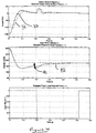
- Figure 4 illustrates a typical second gear to third gear up-shift gear change in a motor vehicle as it traverses substantially level terrain.
- the input pinion shaft velocity will be in the order of 300 rads per second and the gear change will be controlled electronically in accordance with the described previous relationships.
- the input pinion shaft is decelerated to a value in the present example in the order of 40 rads per second below the desired rotational velocity given by the relationship above. This reduction in the rotational speed of the main shaft is shown in Figure 4b by solid line 42.
- broken line 31 indicates the torque provided to the input shaft by the electric motor 1 in order to produce the deceleration to a value below the desired velocity as described previously.
- this torque applied to the input shaft is controlled by the controller using a series of demand signals depicted as solid line 32 utilised as control signals activating reciprocal action in the electric motor to apply the desired level of torque to the input shaft sequentially.
- the solid line 42 depicted in Figure 4b represents variation in the rotational velocity of the input shaft over the time period of a gear selection change. It will be noted that due to the affect of the torque applied to the input shaft by the electric motor at the end of the normal 0.2 second time period in which the speed change transmission is in neutral that the input shaft has a rotational speed below the desired rotational speed 41 for synchronisation with the main shaft. Thus, the input shaft must accelerate to that desired speed for synchronisation rather than decelerate. In such circumstances, as described previously generally, the partial clash in the transmission will be less invasive and produce lower audible noise and gear lever whip etc.
- Figure 5 is a graphic illustration depicting the respective torque factors acting upon the input pinion shaft during gear selection engagement.
- the time period depicted in Figure 5 is essentially the 0.48 to 0.52 second time period in which synchronisation occurs.
- the respective torques from the electric motor decelerating the input shaft and the gearbox loss torque are opposed.
- the net torque upon the input shaft pinion is reduced to zero.
- the gearbox loss torque 51 remains but the applied torque from the electric motor 52 diminishes as it is no longer required in order to alter the rotational speed of the input shaft for the purpose of ensuring an effective downshift gear selection irrespective of the actual gear selection direction.
- the present gear selection arrangement may be used with regard to conventional manually operated transmission or a fully automated manual transmission or a part-automated transmission with a manual clutch and automatic gear selection arrangement.
- the input shaft rotational velocity can be determined by a consideration of the back emf from an electric motor used at the independent drive means for altering rotational speed of the input shaft.
- a specific direct measurand sensor for the input shaft velocity is not required.
- the time period during which the transmission arrangement and in particular the gearbox is in a neutral state where the input shaft 6 and the main shaft are not coupled together is utilised in order to decelerate the input shaft to a velocity just below that required to engage new gear during particularly a up-shift in gear ratios.
- the present invention could also be used with so called clutchless powertrain arrangements where the engine is effectively de-coupled as a drive source by the engine management control system switching off the engine during gear changes.
- the independent drive means can alter the input shaft speed as required to always effectively provide a downshift gear change regime.
- the engine management control systems is an effective clutch means to selectively couple an engine drive shaft to the input shaft operationally in terms of power transfer even though there is always a mechanical coupling therebetween.
Landscapes
- Engineering & Computer Science (AREA)
- Mechanical Engineering (AREA)
- Transportation (AREA)
- Chemical & Material Sciences (AREA)
- Combustion & Propulsion (AREA)
- General Engineering & Computer Science (AREA)
- Automation & Control Theory (AREA)
- Structure Of Transmissions (AREA)
- Control Of Transmission Device (AREA)
Applications Claiming Priority (2)
| Application Number | Priority Date | Filing Date | Title |
|---|---|---|---|
| GB9928239A GB2356903A (en) | 1999-12-01 | 1999-12-01 | Hybrid vehicle with drive motor that synchronises gear in transmission |
| GB9928239 | 1999-12-01 |
Publications (2)
| Publication Number | Publication Date |
|---|---|
| EP1104712A2 true EP1104712A2 (de) | 2001-06-06 |
| EP1104712A3 EP1104712A3 (de) | 2004-11-17 |
Family
ID=10865392
Family Applications (1)
| Application Number | Title | Priority Date | Filing Date |
|---|---|---|---|
| EP00124010A Withdrawn EP1104712A3 (de) | 1999-12-01 | 2000-11-04 | Gangwahleinrichtung für ein Schaltgetriebe |
Country Status (2)
| Country | Link |
|---|---|
| EP (1) | EP1104712A3 (de) |
| GB (1) | GB2356903A (de) |
Cited By (6)
| Publication number | Priority date | Publication date | Assignee | Title |
|---|---|---|---|---|
| DE10217746A1 (de) * | 2002-04-20 | 2003-11-06 | Zf Sachs Ag | Synchronisiereinrichtung für ein Schaltgetriebe und entsprechender Kraftfahrzeug-Antriebsstrang |
| FR2913225A1 (fr) * | 2007-03-01 | 2008-09-05 | Peugeot Citroen Automobiles Sa | Procede de changement de rapport dans une boite de vitesses equipant un vehicule. |
| US7510500B2 (en) | 2003-08-02 | 2009-03-31 | Daimler Ag | Method for controlling a drive of a hybrid vehicle |
| EP2271531A4 (de) * | 2008-04-28 | 2014-06-25 | Mack Trucks | Antriebsstrang mit eingangswelle und motordrehzahlsynchronisierung und verfahren zum schalten von gängen in einem antriebsstrang |
| EP3305618A1 (de) * | 2016-10-06 | 2018-04-11 | Hyundai Motor Company | Verfahren zur steuerung eines elektrischen hybridfahrzeugs |
| EP3887694B1 (de) * | 2019-10-30 | 2022-08-17 | SaLa Drive GmbH | Antrieb, koppelelement sowie verfahren zum betreiben eines antriebes |
Family Cites Families (11)
| Publication number | Priority date | Publication date | Assignee | Title |
|---|---|---|---|---|
| US3478851A (en) * | 1967-08-09 | 1969-11-18 | Smyth Robert Ralston | Automotive transmission |
| GB1435517A (en) * | 1972-09-23 | 1976-05-12 | British Leyland Truck & Bus | Gearbox |
| GB8430235D0 (en) * | 1984-11-30 | 1985-01-09 | Everton J M | Gearbox |
| US5253724A (en) * | 1991-10-25 | 1993-10-19 | Prior Ronald E | Power wheelchair with transmission using multiple motors per drive wheel |
| DE4202083C2 (de) * | 1992-01-25 | 1994-01-20 | Daimler Benz Ag | Hybridantrieb für ein Kraftfahrzeug |
| GB9408923D0 (en) * | 1994-05-05 | 1994-06-22 | Eaton Corp | Power synchronizer for a compound transmission |
| DE4422554C1 (de) * | 1994-06-28 | 1995-10-05 | Daimler Benz Ag | Vorrichtung zur Drehzahlsynchronisation für ein Kraftfahrzeug mit Hybridantrieb |
| FR2766133B1 (fr) * | 1997-07-18 | 1999-09-03 | Renault | Chaine de traction hybride parallele et son procede de commande |
| US5943918A (en) * | 1997-12-01 | 1999-08-31 | Chrysler Corporation | Powertrain system for a hybrid electric vehicle |
| US5979257A (en) * | 1997-12-01 | 1999-11-09 | Chrysler Corporation | Automated manual transmission mode selection controller |
| JP3173450B2 (ja) * | 1998-02-04 | 2001-06-04 | トヨタ自動車株式会社 | ハイブリッド車の駆動制御装置 |
-
1999
- 1999-12-01 GB GB9928239A patent/GB2356903A/en not_active Withdrawn
-
2000
- 2000-11-04 EP EP00124010A patent/EP1104712A3/de not_active Withdrawn
Non-Patent Citations (1)
| Title |
|---|
| None |
Cited By (8)
| Publication number | Priority date | Publication date | Assignee | Title |
|---|---|---|---|---|
| DE10217746A1 (de) * | 2002-04-20 | 2003-11-06 | Zf Sachs Ag | Synchronisiereinrichtung für ein Schaltgetriebe und entsprechender Kraftfahrzeug-Antriebsstrang |
| DE10217746B4 (de) * | 2002-04-20 | 2005-06-16 | Zf Sachs Ag | Synchronisiereinrichtung für ein Schaltgetriebe und entsprechender Kraftfahrzeug-Antriebsstrang |
| US7510500B2 (en) | 2003-08-02 | 2009-03-31 | Daimler Ag | Method for controlling a drive of a hybrid vehicle |
| FR2913225A1 (fr) * | 2007-03-01 | 2008-09-05 | Peugeot Citroen Automobiles Sa | Procede de changement de rapport dans une boite de vitesses equipant un vehicule. |
| EP2271531A4 (de) * | 2008-04-28 | 2014-06-25 | Mack Trucks | Antriebsstrang mit eingangswelle und motordrehzahlsynchronisierung und verfahren zum schalten von gängen in einem antriebsstrang |
| EP3305618A1 (de) * | 2016-10-06 | 2018-04-11 | Hyundai Motor Company | Verfahren zur steuerung eines elektrischen hybridfahrzeugs |
| US10099678B2 (en) | 2016-10-06 | 2018-10-16 | Hyundai Motor Company | Method of controlling hybrid electric vehicle |
| EP3887694B1 (de) * | 2019-10-30 | 2022-08-17 | SaLa Drive GmbH | Antrieb, koppelelement sowie verfahren zum betreiben eines antriebes |
Also Published As
| Publication number | Publication date |
|---|---|
| GB2356903A (en) | 2001-06-06 |
| EP1104712A3 (de) | 2004-11-17 |
| GB9928239D0 (en) | 2000-01-26 |
Similar Documents
| Publication | Publication Date | Title |
|---|---|---|
| EP0173117B1 (de) | Automatisches Getriebe und Verfahren zu seiner Steuerung | |
| US6286381B1 (en) | Gear preselect system for an electro-mechanical automatic transmission having dual input shafts | |
| JP3941906B2 (ja) | 同期噛合式自動変速機の制御装置 | |
| JP4229994B2 (ja) | ツインクラッチ式変速機のシフト方法および同期装置を備えたツインクラッチ式変速機 | |
| US20030054920A1 (en) | Method of controlling a transmission | |
| EP1826462A2 (de) | Vorrichtung und Verfahren zur Fahrzeugsteuerung | |
| JPWO2000032960A1 (ja) | 歯車式自動変速機およびそれを用いた自動車 | |
| US7337052B2 (en) | Method for automatically controlling a transmission brake of an automatic transmission configured as a countershaft transmission | |
| KR20010033540A (ko) | 기어박스 | |
| JP2004251456A (ja) | 複式クラッチ変速機の制御方法 | |
| JP2003269592A (ja) | ツインクラッチ式歯車変速機 | |
| EP0300792B1 (de) | Kontroll-Einrichtungen für automatischen Gangwechsel | |
| US6648795B2 (en) | Transmission system for vehicle | |
| JP2703169B2 (ja) | 自動車の自動変速装置及び自動変速方法 | |
| US5517411A (en) | Neutral attainment control system/method for controlling shifting in vehicular automated mechanical transmission systems | |
| EP1717491B1 (de) | Getriebeanordnung für Kraftfahrzeug | |
| EP1104712A2 (de) | Gangwahleinrichtung für ein Schaltgetriebe | |
| JP2004245325A (ja) | 自動クラッチ式歯車変速機の変速制御装置 | |
| US6878095B2 (en) | Automatic-clutch control system of automatic clutch type transmission | |
| EP1436162B1 (de) | Verfahren- und vorrichtung zur gangschaltsteuerung | |
| JP4007321B2 (ja) | 自動車の制御装置 | |
| JP2862756B2 (ja) | 車両用手動変速装置及びその制御方法 | |
| JP2004522910A (ja) | 自動車駆動ユニット | |
| JP2002340170A (ja) | 自動クラッチ式変速機の変速制御装置 | |
| JPS59106751A (ja) | 車輌用動力伝達装置の自動クラツチ制御方法 |
Legal Events
| Date | Code | Title | Description |
|---|---|---|---|
| PUAI | Public reference made under article 153(3) epc to a published international application that has entered the european phase |
Free format text: ORIGINAL CODE: 0009012 |
|
| AK | Designated contracting states |
Kind code of ref document: A2 Designated state(s): AT BE CH CY DE DK ES FI FR GB GR IE IT LI LU MC NL PT SE TR |
|
| AX | Request for extension of the european patent |
Free format text: AL;LT;LV;MK;RO;SI |
|
| RAP1 | Party data changed (applicant data changed or rights of an application transferred) |
Owner name: BAYERISCHE MOTOREN WERKE AKTIENGESELLSCHAFT |
|
| PUAL | Search report despatched |
Free format text: ORIGINAL CODE: 0009013 |
|
| AK | Designated contracting states |
Kind code of ref document: A3 Designated state(s): AT BE CH CY DE DK ES FI FR GB GR IE IT LI LU MC NL PT SE TR |
|
| AX | Request for extension of the european patent |
Extension state: AL LT LV MK RO SI |
|
| STAA | Information on the status of an ep patent application or granted ep patent |
Free format text: STATUS: THE APPLICATION HAS BEEN WITHDRAWN |
|
| 18W | Application withdrawn |
Effective date: 20050510 |