EP1104736A1 - Dispositif d'assemblage d'un pignon de direction avec un étrier - Google Patents
Dispositif d'assemblage d'un pignon de direction avec un étrier Download PDFInfo
- Publication number
- EP1104736A1 EP1104736A1 EP00403346A EP00403346A EP1104736A1 EP 1104736 A1 EP1104736 A1 EP 1104736A1 EP 00403346 A EP00403346 A EP 00403346A EP 00403346 A EP00403346 A EP 00403346A EP 1104736 A1 EP1104736 A1 EP 1104736A1
- Authority
- EP
- European Patent Office
- Prior art keywords
- nut
- pinion
- cylindrical
- caliper
- stirrup
- Prior art date
- Legal status (The legal status is an assumption and is not a legal conclusion. Google has not performed a legal analysis and makes no representation as to the accuracy of the status listed.)
- Granted
Links
- 230000000295 complement effect Effects 0.000 claims abstract description 4
- 238000007747 plating Methods 0.000 description 2
- 239000004677 Nylon Substances 0.000 description 1
- 230000004323 axial length Effects 0.000 description 1
- 230000000903 blocking effect Effects 0.000 description 1
- 229920001778 nylon Polymers 0.000 description 1
- 238000010079 rubber tapping Methods 0.000 description 1
Images

Classifications
-
- F—MECHANICAL ENGINEERING; LIGHTING; HEATING; WEAPONS; BLASTING
- F16—ENGINEERING ELEMENTS AND UNITS; GENERAL MEASURES FOR PRODUCING AND MAINTAINING EFFECTIVE FUNCTIONING OF MACHINES OR INSTALLATIONS; THERMAL INSULATION IN GENERAL
- F16D—COUPLINGS FOR TRANSMITTING ROTATION; CLUTCHES; BRAKES
- F16D1/00—Couplings for rigidly connecting two coaxial shafts or other movable machine elements
- F16D1/06—Couplings for rigidly connecting two coaxial shafts or other movable machine elements for attachment of a member on a shaft or on a shaft-end
- F16D1/08—Couplings for rigidly connecting two coaxial shafts or other movable machine elements for attachment of a member on a shaft or on a shaft-end with clamping hub; with hub and longitudinal key
- F16D1/0817—Couplings for rigidly connecting two coaxial shafts or other movable machine elements for attachment of a member on a shaft or on a shaft-end with clamping hub; with hub and longitudinal key with radial clamping due to rotation along an eccentric surface, e.g. arcuate wedging elements
-
- B—PERFORMING OPERATIONS; TRANSPORTING
- B62—LAND VEHICLES FOR TRAVELLING OTHERWISE THAN ON RAILS
- B62D—MOTOR VEHICLES; TRAILERS
- B62D1/00—Steering controls, i.e. means for initiating a change of direction of the vehicle
- B62D1/02—Steering controls, i.e. means for initiating a change of direction of the vehicle vehicle-mounted
- B62D1/16—Steering columns
Definitions
- the present invention relates to a device intended to allow the assembly of a steering gear of a vehicle with a stirrup fixed to the end of a steering tree.
- the publication FR-2.741.407 describes a device of this type in which a screw comes to cooperate with a nut, the nut and the screw being in contact with the two faces of the caliper at the end of assembly.
- a tongue elastic carried by an arm secured to the stirrup keeps the nut in a hole stirrup correspondent.
- the present invention proposes to overcome these drawbacks.
- the present invention provides an assembly device intended for connecting two elements of a motor vehicle steering column, of the type comprising a stirrup secured to an automobile steering column in which comes to engage a complementary member such as a pinion integral with the axis of the steering box, and a pinion clamping member in the caliper comprising a screw with a head and a threaded end, characterized in that the end threaded screw cooperates with a nut mounted in a nut holder, said nut support being carried by one of the legs of the stirrup and in that the nut is able to move inside the nut holder between a position allowing the mounting of the pinion between the arms of the caliper and a position ensuring the tightening of the pinion and the caliper.
- the nut support includes a cylindrical tubular member with one end closed by a wall pierced with a central hole.
- the nut is maintained in axial position authorizing the mounting of the pinion between the branches of the stirrup by the nut holder wall and a nut lock mounted in the central hole.
- the nut comprises at one from its ends a cylindrical radial collar of which one of the axial surfaces is extends by a conical external surface flared towards the axis of the nut.
- a first part cylindrical of the nut protrudes from the other axial surface of the collar and extends by a second cylindrical part eccentric with respect to the first.
- the external surfaces of the two cylindrical parts are connected by a chamfer, the second part cylindrical internally tangent to the first cylindrical part.
- the fixing device according to the invention shown in Figures 1 to 5 is relates to a screw 3 and a nut 5 which are intended to assemble an element in stirrup shape 1 secured to an automobile steering column with a pinion 2 secured to the axis of the steering box.
- the stirrup-shaped element 1 has a U-shaped section which has two branches substantially parallel to each other and which are connected by an element transverse.
- the two legs of the stirrup are connected to the end of the column steering by a universal joint (not shown).
- the pinion 2 engages between the branches of the stirrup 1; this pinion 2 has a non-circular section and has three flats and a cylindrical sector.
- two flats are arranged symmetrically with respect to the cylindrical sector and are parallel to each other so that ability to slide between the legs of the stirrup.
- the third flat is perpendicular to the other two flats.
- a hole 11 is arranged in the branch of the stirrup.
- the hole has dimensions which correspond to the passage of the screw rod, and it is aligned with a housing 12 which has larger dimensions so as to match the dimensions of a nut 5.
- the nut 5 of the monobloc type has at one of its ends a collar 51 radial cylindrical with one of its axial surfaces extended by an external surface conical 511 flared towards the axis of the nut 5.
- a first cylindrical part 53 projects from the other axial surface of the collar 51 and is extended by a second cylindrical part 55 which is offset from the first; the external surfaces of the two cylindrical parts are connected by a chamfer 54; the second cylindrical part tangent internally the first cylindrical part.
- the end of the second cylindrical part ends in a chamfer.
- the nut 5 is crossed by a cylindrical bore 57 coaxial with the axis of the collar and whose dimensions allow the passage of the screw rod 3.
- This bore has a first cylindrical internal surface, smooth 571, which extended by a second cylindrical internal threaded surface 572 with a diameter less than the diameter of the first internal surface.
- An elastic ring (not shown) is mounted in a groove formed on the internal face of the thread; the function of this elastic ring is to train the nut in rotation during the screwing and to guarantee the plating of the nut against the pinion 2; this function can be achieved, for example, by an elastic ring nylon or by a deformation of the thread of the thread.
- the nut is mounted in a housing of a nut holder 4.
- the nut support 4 is constituted by a cylindrical tubular element, one of which ends is closed by a wall pierced with a central hole 42; the other end of the nut support 4 is open and ends with a flange 43 projecting radially outward.
- the nut 5 is secured to the nut support by a nut brake 6 constituted by a head extended by a cylindrical body which cooperates with the internal thread nut 3; the nut brake head 6 is applied against the external surface of the wall of the nut support.
- the nut is therefore held in the axial position by the nut holder wall and nut lock.
- a flat 512 of the nut 5 cooperates with a complementary flat 41 of the support nut which keeps the nut 5 in rotation relative to the body nut 4.
- the flange 43 of the nut support 4 is crimped on the external face of one of the stirrup branches.
- the screw 3 penetrates in the hole 11 arranged in the branch of the stirrup 1 and comes to engage in the threaded part of nut 5 which is mounted in nut holder 4 fixed on the other external face of the caliper 1.
- the pinion 2 engages inside the caliper 1 and its position is ensured at the end of blocking by the screw 3 which engages under this pinion.
- the device according to the invention makes it possible to guarantee the presence of the nut in all cases which avoids the trial and error previously imposed on the operator during the mounting; the assembly time is reduced accordingly.
- this device improves the plating and the tightening of the pinion. against the stirrup.
Landscapes
- Engineering & Computer Science (AREA)
- Mechanical Engineering (AREA)
- General Engineering & Computer Science (AREA)
- Chemical & Material Sciences (AREA)
- Combustion & Propulsion (AREA)
- Transportation (AREA)
- Braking Arrangements (AREA)
- Steering Controls (AREA)
- Steering Devices For Bicycles And Motorcycles (AREA)
Abstract
Description
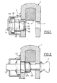
- la figure 1 est une vue en coupe axiale d'un système de fixation par vis et écrou d'un étrier d'une colonne de direction de véhicule automobile devant être assemblé avec un élément solidaire de l'axe du boítier de direction, l'ensemble étant représenté avant assemblage,
- la figure 2 est une vue en coupe axiale d'un système de fixation par vis et écrou d'un étrier d'une colonne de direction de véhicule automobile devant être assemblé avec un élément solidaire de l'axe du boítier de direction, l'ensemble étant représenté après assemblage,
- la figure 3 est une vue en perspective du système de fixation représenté à la figure 1,
- la figure 4 est une vue de détail de la figure 2,
- la figure 5 est une vue de côté de la figure 4.
- dans un premier temps, la paroi axiale du support d'écrou 4 et le frein d'écrou 6 assurent un positionnement relatif temporaire en rotation et axial de sorte que la vis 3 vienne s'engager correctement dans l'écrou 5 ; lorsque les filets de la vis sont en prise avec une longueur suffisante du taraudage de l'écrou, l'extrémité de la vis éjecte le frein d'écrou 6.
- dans un deuxième temps, au delà d'une certaine course en translation pure de l'écrou qui correspond à la longueur axiale des méplats 41, 512 l'écrou est entraíné en rotation et le cylindre excentré 55 de l'écrou 5 vient alors plaquer l'élément à assembler contre l'étrier 1 de manière à assurer un fonctionnement sans jeu du dispositif
Claims (6)
- Dispositif d'assemblage destiné à relier deux éléments d'une colonne de direction de véhicule automobile, du type comprenant un étrier (1) solidaire d'une colonne de direction d'automobile dans lequel vient s'engager un organe complémentaire tel qu'un pignon (2) solidaire de l'axe du boítier de direction, et un organe de serrage du pignon dans l'étrier comprenant une vis (3) dotée d'une tête et d'une extrémité filetée, caractérisé en ce que l'extrémité filetée de la vis coopère avec un écrou (5) monté dans un support d'écrou (4), ledit support (4) d'écrou étant porté par l'une des branches de l'étrier (1) et en ce que l'écrou (5) est apte à se déplacer à l'intérieur du support d'écrou entre une position permettant le montage du pignon entre les branches de l'étrier et une position assurant le serrage du pignon et de l'étrier.
- Dispositif selon la revendication 1, caractérisé en ce que le support d'écrou (4) comprend un élément tubulaire cylindrique dont l'une des extrémités est fermée par une paroi percée d'un trou central (42).
- Dispositif selon la revendication 2, caractérisé en ce que l'écrou (5) est maintenu en position axiale autorisant le montage du pignon (6) entre les branches de l'étrier (1) par la paroi du support d'écrou et un frein d'écrou (6) monté dans le trou central (42).
- Dispositif selon l'une des revendications précédentes, caractérisé en ce que l'écrou (5) comporte à l'une de ses extrémités un collet (51) radial cylindrique dont l'une des surfaces axiales se prolonge par une surface externe conique (511) évasée vers l'axe de l'écrou (5).
- Dispositif selon la revendication 4, caractérisé en ce qu'une première partie cylindrique (53) de l'écrou fait saillie de l'autre surface axiale du collet (51) et se prolonge par une seconde partie cylindrique (55) excentrée par rapport à la première.
- Dispositif selon la revendication 5, caractérisé en ce que les surfaces externes des deux parties cylindriques (53,55) sont reliées par un chanfrein (54) et en ce que la seconde partie cylindrique tangente intérieurement la première partie cylindrique.
Applications Claiming Priority (2)
| Application Number | Priority Date | Filing Date | Title |
|---|---|---|---|
| FR9915251 | 1999-12-03 | ||
| FR9915251A FR2801860B1 (fr) | 1999-12-03 | 1999-12-03 | Dispositif d'assemblage d'un pignon de direction avec un etrier |
Publications (2)
| Publication Number | Publication Date |
|---|---|
| EP1104736A1 true EP1104736A1 (fr) | 2001-06-06 |
| EP1104736B1 EP1104736B1 (fr) | 2004-08-11 |
Family
ID=9552849
Family Applications (1)
| Application Number | Title | Priority Date | Filing Date |
|---|---|---|---|
| EP20000403346 Expired - Lifetime EP1104736B1 (fr) | 1999-12-03 | 2000-11-30 | Dispositif d'assemblage d'un pignon de direction avec un étrier |
Country Status (4)
| Country | Link |
|---|---|
| EP (1) | EP1104736B1 (fr) |
| DE (1) | DE60012851T2 (fr) |
| ES (1) | ES2226746T3 (fr) |
| FR (1) | FR2801860B1 (fr) |
Cited By (1)
| Publication number | Priority date | Publication date | Assignee | Title |
|---|---|---|---|---|
| EP1840398A1 (fr) * | 2006-03-30 | 2007-10-03 | JTEKT Corporation | Joint universel |
Families Citing this family (2)
| Publication number | Priority date | Publication date | Assignee | Title |
|---|---|---|---|---|
| DE102005033627A1 (de) * | 2005-07-19 | 2007-01-25 | GM Global Technology Operations, Inc., Detroit | Vorrichtung zur Verbindung einer Zwischenwelle mit einem Ritzel eines Lenkgetriebes |
| DE102005033626A1 (de) * | 2005-07-19 | 2007-02-01 | GM Global Technology Operations, Inc., Detroit | Klemmstück zur Verbindung einer Zwischenwelle mit dem Ritzel eines Lenkgetriebes |
Citations (3)
| Publication number | Priority date | Publication date | Assignee | Title |
|---|---|---|---|---|
| FR1019367A (fr) * | 1950-05-31 | 1953-01-21 | Gkn Group Services Ltd | Perfectionnements apportés aux écrous indesserrables |
| FR2741407A1 (fr) | 1995-11-20 | 1997-05-23 | Ecia Equip Composants Ind Auto | Dispositif de maintien en position d'un organe de serrage |
| GB2312034A (en) * | 1996-04-13 | 1997-10-15 | Delphi France Automotive Sys | Yoke assembly for a universal joint |
-
1999
- 1999-12-03 FR FR9915251A patent/FR2801860B1/fr not_active Expired - Fee Related
-
2000
- 2000-11-30 EP EP20000403346 patent/EP1104736B1/fr not_active Expired - Lifetime
- 2000-11-30 ES ES00403346T patent/ES2226746T3/es not_active Expired - Lifetime
- 2000-11-30 DE DE2000612851 patent/DE60012851T2/de not_active Expired - Lifetime
Patent Citations (3)
| Publication number | Priority date | Publication date | Assignee | Title |
|---|---|---|---|---|
| FR1019367A (fr) * | 1950-05-31 | 1953-01-21 | Gkn Group Services Ltd | Perfectionnements apportés aux écrous indesserrables |
| FR2741407A1 (fr) | 1995-11-20 | 1997-05-23 | Ecia Equip Composants Ind Auto | Dispositif de maintien en position d'un organe de serrage |
| GB2312034A (en) * | 1996-04-13 | 1997-10-15 | Delphi France Automotive Sys | Yoke assembly for a universal joint |
Cited By (2)
| Publication number | Priority date | Publication date | Assignee | Title |
|---|---|---|---|---|
| EP1840398A1 (fr) * | 2006-03-30 | 2007-10-03 | JTEKT Corporation | Joint universel |
| US7513709B2 (en) | 2006-03-30 | 2009-04-07 | Jtekt Corporation | Universal joint |
Also Published As
| Publication number | Publication date |
|---|---|
| FR2801860B1 (fr) | 2002-02-01 |
| DE60012851D1 (de) | 2004-09-16 |
| EP1104736B1 (fr) | 2004-08-11 |
| ES2226746T3 (es) | 2005-04-01 |
| FR2801860A1 (fr) | 2001-06-08 |
| DE60012851T2 (de) | 2005-09-01 |
Similar Documents
| Publication | Publication Date | Title |
|---|---|---|
| EP1241072B1 (fr) | Assemblage d'un étrier de colonne de direction avec un pignon de direction d'un véhicule automobile | |
| EP0551047B1 (fr) | Dispositif de fixation à butée-guide axiale escamotable | |
| EP0309344A1 (fr) | Dispositif d'accouplement pour une colonne de direction et véhicule équipé d'un tel dispositif | |
| EP0706929B1 (fr) | Dispositif de fixation d'un moyeu de volant de direction de véhicule automobile sur un arbre de direction | |
| EP1104736B1 (fr) | Dispositif d'assemblage d'un pignon de direction avec un étrier | |
| FR2798099A1 (fr) | Siege de vehicule dote d'un mecanisme d'articulation | |
| EP0395460B1 (fr) | Frein à disque à étrier coulissant | |
| FR2865007A1 (fr) | Dispositif de verrouillage reversible sur une structure d'un embout a positionnement ajustable | |
| FR2928986A1 (fr) | Joint imperdable pour raccord banjo et ensemble comportant un raccord banjo et un tel joint | |
| EP1092880A1 (fr) | Système à rattrapage de jeu pour fixer deux pièces l'une à l'autre au moyen d'un organe de fixation du type à vis | |
| FR2715906A1 (fr) | Dispositif de fixation d'un organe sur un arbre de direction notamment de véhicule automobile. | |
| EP0059657A1 (fr) | Valve de servodirection à montage simplifié | |
| FR2815924A1 (fr) | Dispositif d'assemblage d'un etrier de colonne de direction avec un pignon de direction d'un vehicule automobile | |
| FR3099089A1 (fr) | Palier et pièce de réglage pour train multi-bras | |
| EP1270962B1 (fr) | Dispositif de liaison mécanique sécurisé | |
| EP0893333B1 (fr) | Dispositif de connexion de maillons de chenilles | |
| FR2668240A1 (fr) | Dispositif de raccordement de deux tuyaux de part et d'autre d'un element de cloison. | |
| FR2921704A1 (fr) | Assemblage securise d'une premiere piece sur une deuxieme piece au moyen d'un organe de vissage | |
| WO1999008037A1 (fr) | Dispositif de raccordement rapide d'un tube a un element rigide | |
| FR2764950A1 (fr) | Dispositif anti-boitement et anti-extraction d'un ensemble coulissant | |
| EP0679827B1 (fr) | Dispositif de raccordement pour circuit hydraulique haute pression | |
| EP1637747B1 (fr) | Agencement de fixation d'un élèment d'équipement pour véhicule automobile | |
| FR3057924B1 (fr) | Etrier de frein avec compression axiale d'un joint d'etancheite entre un carter d'actionneur et un corps d'etrier | |
| FR2900618A1 (fr) | Dispositif de liaison entre une estremite de tige de commande d'amplificateur de frein et un bras de pedale de frein | |
| FR3134610A1 (fr) | Elément de liaison d’un tube de canalisation à un support de palier et turbomachine équipée d’un tel élément de liaison. |
Legal Events
| Date | Code | Title | Description |
|---|---|---|---|
| PUAI | Public reference made under article 153(3) epc to a published international application that has entered the european phase |
Free format text: ORIGINAL CODE: 0009012 |
|
| AK | Designated contracting states |
Kind code of ref document: A1 Designated state(s): BE DE ES |
|
| AX | Request for extension of the european patent |
Free format text: AL;LT;LV;MK;RO;SI |
|
| 17P | Request for examination filed |
Effective date: 20011128 |
|
| AKX | Designation fees paid |
Free format text: BE DE ES |
|
| RAP1 | Party data changed (applicant data changed or rights of an application transferred) |
Owner name: RENAULT S.A.S. |
|
| GRAP | Despatch of communication of intention to grant a patent |
Free format text: ORIGINAL CODE: EPIDOSNIGR1 |
|
| GRAS | Grant fee paid |
Free format text: ORIGINAL CODE: EPIDOSNIGR3 |
|
| GRAA | (expected) grant |
Free format text: ORIGINAL CODE: 0009210 |
|
| AK | Designated contracting states |
Kind code of ref document: B1 Designated state(s): BE DE ES |
|
| REF | Corresponds to: |
Ref document number: 60012851 Country of ref document: DE Date of ref document: 20040916 Kind code of ref document: P |
|
| REG | Reference to a national code |
Ref country code: ES Ref legal event code: FG2A Ref document number: 2226746 Country of ref document: ES Kind code of ref document: T3 |
|
| PLBE | No opposition filed within time limit |
Free format text: ORIGINAL CODE: 0009261 |
|
| STAA | Information on the status of an ep patent application or granted ep patent |
Free format text: STATUS: NO OPPOSITION FILED WITHIN TIME LIMIT |
|
| 26N | No opposition filed |
Effective date: 20050512 |
|
| PGFP | Annual fee paid to national office [announced via postgrant information from national office to epo] |
Ref country code: DE Payment date: 20101119 Year of fee payment: 11 |
|
| PGFP | Annual fee paid to national office [announced via postgrant information from national office to epo] |
Ref country code: ES Payment date: 20111125 Year of fee payment: 12 |
|
| PGFP | Annual fee paid to national office [announced via postgrant information from national office to epo] |
Ref country code: BE Payment date: 20111110 Year of fee payment: 12 |
|
| BERE | Be: lapsed |
Owner name: *RENAULT S.A.S. Effective date: 20121130 |
|
| PG25 | Lapsed in a contracting state [announced via postgrant information from national office to epo] |
Ref country code: BE Free format text: LAPSE BECAUSE OF NON-PAYMENT OF DUE FEES Effective date: 20121130 |
|
| REG | Reference to a national code |
Ref country code: DE Ref legal event code: R119 Ref document number: 60012851 Country of ref document: DE Effective date: 20130601 |
|
| PG25 | Lapsed in a contracting state [announced via postgrant information from national office to epo] |
Ref country code: DE Free format text: LAPSE BECAUSE OF NON-PAYMENT OF DUE FEES Effective date: 20130601 |
|
| REG | Reference to a national code |
Ref country code: ES Ref legal event code: FD2A Effective date: 20140513 |
|
| PG25 | Lapsed in a contracting state [announced via postgrant information from national office to epo] |
Ref country code: ES Free format text: LAPSE BECAUSE OF NON-PAYMENT OF DUE FEES Effective date: 20121201 |