EP1104840A2 - Moteur à combustion interne - Google Patents
Moteur à combustion interne Download PDFInfo
- Publication number
- EP1104840A2 EP1104840A2 EP00112453A EP00112453A EP1104840A2 EP 1104840 A2 EP1104840 A2 EP 1104840A2 EP 00112453 A EP00112453 A EP 00112453A EP 00112453 A EP00112453 A EP 00112453A EP 1104840 A2 EP1104840 A2 EP 1104840A2
- Authority
- EP
- European Patent Office
- Prior art keywords
- combustion engine
- internal combustion
- cylinder
- valve seat
- engine according
- Prior art date
- Legal status (The legal status is an assumption and is not a legal conclusion. Google has not performed a legal analysis and makes no representation as to the accuracy of the status listed.)
- Withdrawn
Links
- 238000002485 combustion reaction Methods 0.000 title claims abstract description 98
- 239000000725 suspension Substances 0.000 claims abstract 2
- 239000000203 mixture Substances 0.000 claims description 43
- 230000006835 compression Effects 0.000 claims description 30
- 238000007906 compression Methods 0.000 claims description 30
- 230000007246 mechanism Effects 0.000 claims description 25
- 239000000446 fuel Substances 0.000 claims description 14
- 238000000034 method Methods 0.000 claims description 5
- 230000002093 peripheral effect Effects 0.000 claims 1
- 238000011144 upstream manufacturing Methods 0.000 claims 1
- 239000007789 gas Substances 0.000 description 25
- 239000002360 explosive Substances 0.000 description 12
- 230000001174 ascending effect Effects 0.000 description 3
- 230000009467 reduction Effects 0.000 description 3
- 230000008901 benefit Effects 0.000 description 2
- 239000000567 combustion gas Substances 0.000 description 2
- 230000007613 environmental effect Effects 0.000 description 2
- 238000004880 explosion Methods 0.000 description 2
- 239000002699 waste material Substances 0.000 description 2
- 208000027418 Wounds and injury Diseases 0.000 description 1
- 230000002411 adverse Effects 0.000 description 1
- 230000008033 biological extinction Effects 0.000 description 1
- 238000007664 blowing Methods 0.000 description 1
- 238000010276 construction Methods 0.000 description 1
- 238000007796 conventional method Methods 0.000 description 1
- 230000006378 damage Effects 0.000 description 1
- 230000008030 elimination Effects 0.000 description 1
- 238000003379 elimination reaction Methods 0.000 description 1
- 208000014674 injury Diseases 0.000 description 1
- 238000009434 installation Methods 0.000 description 1
- 230000003993 interaction Effects 0.000 description 1
- 238000002360 preparation method Methods 0.000 description 1
- 230000008569 process Effects 0.000 description 1
- 230000000717 retained effect Effects 0.000 description 1
- 230000000630 rising effect Effects 0.000 description 1
Images


Classifications
-
- F—MECHANICAL ENGINEERING; LIGHTING; HEATING; WEAPONS; BLASTING
- F01—MACHINES OR ENGINES IN GENERAL; ENGINE PLANTS IN GENERAL; STEAM ENGINES
- F01C—ROTARY-PISTON OR OSCILLATING-PISTON MACHINES OR ENGINES
- F01C1/00—Rotary-piston machines or engines
- F01C1/30—Rotary-piston machines or engines having the characteristics covered by two or more groups F01C1/02, F01C1/08, F01C1/22, F01C1/24 or having the characteristics covered by one of these groups together with some other type of movement between co-operating members
- F01C1/34—Rotary-piston machines or engines having the characteristics covered by two or more groups F01C1/02, F01C1/08, F01C1/22, F01C1/24 or having the characteristics covered by one of these groups together with some other type of movement between co-operating members having the movement defined in group F01C1/08 or F01C1/22 and relative reciprocation between the co-operating members
- F01C1/344—Rotary-piston machines or engines having the characteristics covered by two or more groups F01C1/02, F01C1/08, F01C1/22, F01C1/24 or having the characteristics covered by one of these groups together with some other type of movement between co-operating members having the movement defined in group F01C1/08 or F01C1/22 and relative reciprocation between the co-operating members with vanes reciprocating with respect to the inner member
- F01C1/3446—Rotary-piston machines or engines having the characteristics covered by two or more groups F01C1/02, F01C1/08, F01C1/22, F01C1/24 or having the characteristics covered by one of these groups together with some other type of movement between co-operating members having the movement defined in group F01C1/08 or F01C1/22 and relative reciprocation between the co-operating members with vanes reciprocating with respect to the inner member the inner and outer member being in contact along more than one line or surface
-
- F—MECHANICAL ENGINEERING; LIGHTING; HEATING; WEAPONS; BLASTING
- F02—COMBUSTION ENGINES; HOT-GAS OR COMBUSTION-PRODUCT ENGINE PLANTS
- F02B—INTERNAL-COMBUSTION PISTON ENGINES; COMBUSTION ENGINES IN GENERAL
- F02B75/00—Other engines
- F02B75/02—Engines characterised by their cycles, e.g. six-stroke
- F02B2075/022—Engines characterised by their cycles, e.g. six-stroke having less than six strokes per cycle
- F02B2075/027—Engines characterised by their cycles, e.g. six-stroke having less than six strokes per cycle four
-
- F—MECHANICAL ENGINEERING; LIGHTING; HEATING; WEAPONS; BLASTING
- F02—COMBUSTION ENGINES; HOT-GAS OR COMBUSTION-PRODUCT ENGINE PLANTS
- F02B—INTERNAL-COMBUSTION PISTON ENGINES; COMBUSTION ENGINES IN GENERAL
- F02B53/00—Internal-combustion aspects of rotary-piston or oscillating-piston engines
Definitions
- the present invention relates to an internal combustion engine, comprising a cylinder block and a main rotor which concentric in the circular cylinder of the cylinder block is arranged, the fuel-air mixture which at rotating main rotor is induced in the cylinder Combustion chambers, which are in the circumferential surface of the Main rotor are arranged, is compressed and when the rotating combustion chamber aligned with the ignition system, it will Fuel-air mixture detonated to advance generate that is suitable to the main rotor naturally and rotate continuously in the same direction allow to produce kinetic energy to achieve maximum efficiency.
- the two-stroke internal combustion engine is constructed so that the piston the fuel-air mixture compresses as it climbs to the top goal point, then the compressed fuel-air mixture through an ignition system is ignited to by an explosive combustion force to transmit the descending piston, which on the Crankshaft is transmitted, with the rotation of the Crankshaft kinetic energy is generated.
- the piston is through an explosive combustion of the air / fuel mixture in Movement brought and after reaching top dead center immediately moved down again, creating a force on the Crankshaft is exercised, which creates a rotation generated by kinetic energy.
- the piston After the rotation of the Crankshaft by 180 ° and the one generated by this 180 ° rotation kinetic energy, the piston reaches bottom dead center, which turns into a further 180 ° rotation, the one Ascending the piston in the opposite direction and one Compression of the fuel-air mixture allows, where no force is exerted on the crankshaft here, but the crankshaft rotates due to the stored Moment of inertia by another 180 °, but not due to one driving force that is continuously exerted on the pistons becomes.
- the piston is unsuitable, a constant driving force when moving up and down on the crankshaft exercise, but is only suitable for this to exercise during a single downward movement.
- the kinetic energy generated by the Crankshaft is generated, only half of the possible Performance and this obvious disadvantage means one Reduction of efficiency.
- the structure of the four-stroke internal combustion engine now described has been designed the disadvantages regarding the large amount of combustion gases which Cylinder of the two-stroke internal combustion engine after the explosive Avoid burns. He is also one of them suitable to generate kinetic energy by opening and closing Movement of the piston which is transferred to the crankshaft becomes.
- the four-stroke internal combustion engine also differs from the two-stroke internal combustion engine in that that the piston two up and down movements or the Crankshaft two turns (720 °) to generate one single unit of kinetic energy must perform. For example, if the intake and exhaust valves are both closed the piston rises for the first stroke by Compress fuel-air mixture in the cylinder and then when he reaches top dead center, it will Fuel-air mixture through an ignition system in one explosive combustion.
- a multiple combustion chamber and a flexible Compression mechanism of a single-stroke internal combustion engine To make available, said cylinder one has a circular structure and in the cylinder wall at least one throttle valve seat with a minor smaller diameter is arranged.
- a main rotor is concentric in the cylinder and a combustion chamber is in the circumferential surface arranged and an ignition system is in Area of the throttle valve seat provided.
- the compressed Air-fuel mixture contained in it immediately to generate feed to the explosion brought, the main rotor rotates naturally and without One-way break to produce kinetic Energy with maximum efficiency, without the natural laws to hurt the movement or make a loss Accept inertia forces.
- Another object of the present invention is to provide a Multiple combustion chamber and a single-stroke internal combustion engine with to provide a flexible compression mechanism, each throttle valve seat in the following order an ignition system, an exhaust and an intake device includes.
- a flexible compression mechanism is nearby the further extension of each combustion chamber on the Main rotor attached, which is also in permanent Contact with the cylinder wall or the throttle valve seat Maintaining a pressure-tight connection.
- Another object of the present invention is to provide a Multiple combustion chamber and a flexible Compression mechanism of a single-stroke internal combustion engine
- To provide with the main rotor directly into the explosive combustion of the fuel-air mixture included is natural to a natural rotation without injury Laws or elimination of inertial forces too guarantee and also the direct provision of kinetic energy without the need for pistons, Connecting rod, crankshaft and other related components as is the case with conventional methods of generating kinetic energy is common to provide, whereby not just the loss of kinetic energy and exhaust gases is effectively improved, but also many ecological Advantages are achieved.
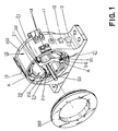
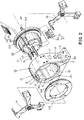
- this essentially comprises two structural components: a cylinder block 10 and a main rotor 20.
- the cylinder block 10 has a circular cylinder 101 which lies flat against the cylinder wall 1011, the circular cylinder 101 comprising at least one concentrically arranged throttle valve seat 102 with a slightly smaller segmented diameter (the preferred embodiment in the drawings shows a throttle valve seat 102 on the left and right side), with a linked curve B providing an active distance between the throttle valve seat 102 and the cylinder wall 1011, an ignition system 11 (for example a spark plug), an outlet 12 and an air intake device 13 (including the intake valve and carburetor etc.) in the following order. ) is provided.
- the main rotor 20 is essentially annular Shape up and is concentric in the circular Cylinder 101 of the cylinder block 10 arranged, this comprises a shaft 201 at its center, which one free rotation in the holding devices 14 on the two Sides of the cylinder block 10, the circumferential At least surface 1011 of circular cylinder 102 a throttle valve seat 102 along the range of circular cylinder 101 and at least one prechamber A comprises which between the main rotor 20 and the cylindrical wall 1011 is arranged.
- the flexible one Compression mechanism 21 slides in a coordinated manner Contact along surface 1011 and the throttle valve seat 102.
- a hermetic housing 202 is equipped with an expansion seal provided in 2021 both ends of the cylinder block 10 are attached that a pressure-resistant housing is retained, as a result of which the cylinder 101 is enabled to form a closed space.
- at least one flexible compression mechanism 21 along the circumferential surface of the main rotor 20 (which here The preferred embodiment shown comprises three flexible Compression mechanisms 21) are provided and a combustion chamber 203 one tiered flat front and one deep rear Profile near the forward end of each has flexible compression mechanism 21.
- the Throttle element is suitable against the spring element to be braced so that a pressure-resistant arrangement between the cylinder wall 1011 or the throttle valve seats 102 of the cylinder block 10 can be produced.
- Embodiment of the present invention is Main rotor 20 suitable for free after installation in the to rotate circular cylinder 101 of cylinder block 10, circular cylinder 101 being a closed one Room 101 defines, with gas currently blowing through occurs when the fuel-air mixture in the pre-chamber A is transmitted through the air intake device 13, the coordinated sliding contact between the circumferential surface of the main rotor 20 and the throttle valve seats 102 and Cylinder wall 1011 enables an optimal air density.
- the flexible compression mechanism 21 is able to compressed fuel-air mixture from the pre-chamber A in to transfer the combustion chamber 203 while the main rotor 20 rotates, causing continuous combustion by the Ignition system 11 and thus the generation of feed is ensured so that the main rotor 20 without constraint and constant in one direction without being affected by Inertia according to the natural laws of rotation rotates and thus kinetic energy with maximum efficiency provides.
- the active distance is determined by the rounding b between the circular cylinder wall 1011 of the Cylinder blocks 10 and throttle valve seat 102 provided, the flexible compression mechanism 21 with the main rotor 21 rotated along it, the spring-controlled throttle element 211 not only smooth and extends, but also a pressure-resistant connection opposite the cylinder wall 1011 and the throttle valve 102 maintains.
- the main rotor 20th at least one flexible compression mechanism 21 and includes a combustion chamber 203, one as needed Variety of throttle valve seats 102, flexible Compression mechanisms 21 and combustion chambers 203 subsequently can be introduced into the main rotor 20, wherein additional power and speed is produced, and thus providing greater kinetic energy becomes.
- the throttle valve seat must be selected 102, the flexible compression mechanism 21 and the Combustion chamber 203 under a suitable configuration Taking into account the circular cylinder wall 1011 and the Cylinder blocks 10 and the main rotor 20 are taken into account become.
Landscapes
- Engineering & Computer Science (AREA)
- Mechanical Engineering (AREA)
- General Engineering & Computer Science (AREA)
- Chemical & Material Sciences (AREA)
- Combustion & Propulsion (AREA)
- Combustion Methods Of Internal-Combustion Engines (AREA)
Applications Claiming Priority (2)
| Application Number | Priority Date | Filing Date | Title |
|---|---|---|---|
| US452395 | 1982-12-22 | ||
| US45239599A | 1999-12-01 | 1999-12-01 |
Publications (2)
| Publication Number | Publication Date |
|---|---|
| EP1104840A2 true EP1104840A2 (fr) | 2001-06-06 |
| EP1104840A3 EP1104840A3 (fr) | 2002-05-15 |
Family
ID=23796287
Family Applications (1)
| Application Number | Title | Priority Date | Filing Date |
|---|---|---|---|
| EP00112453A Withdrawn EP1104840A3 (fr) | 1999-12-01 | 2000-06-10 | Moteur à combustion interne |
Country Status (2)
| Country | Link |
|---|---|
| EP (1) | EP1104840A3 (fr) |
| KR (1) | KR20010066854A (fr) |
Cited By (1)
| Publication number | Priority date | Publication date | Assignee | Title |
|---|---|---|---|---|
| EP3222810A1 (fr) * | 2016-03-24 | 2017-09-27 | Rong-Jen Wu | Moteur à combustion interne à un temps |
Family Cites Families (5)
| Publication number | Priority date | Publication date | Assignee | Title |
|---|---|---|---|---|
| DE466365C (de) * | 1925-12-13 | 1928-10-04 | Otto Baessler | Umsteuerschieber fuer Drehkolben-Kraftmaschinen mit mehrfacher Expansion |
| US1792026A (en) * | 1928-07-03 | 1931-02-10 | Hart E Nichols | Rotary internal-combustion engine |
| FR1009674A (fr) * | 1948-06-16 | 1952-06-03 | Moteur à explosion rotatif | |
| DE2830854A1 (de) * | 1978-07-13 | 1980-01-24 | Ingo Gierstorfer | Kreiskolbenmotor |
| GB8420682D0 (en) * | 1984-08-15 | 1984-09-19 | Yang T H | Ic engine |
-
2000
- 2000-06-10 EP EP00112453A patent/EP1104840A3/fr not_active Withdrawn
- 2000-06-20 KR KR1020000033751A patent/KR20010066854A/ko not_active Ceased
Non-Patent Citations (1)
| Title |
|---|
| None |
Cited By (1)
| Publication number | Priority date | Publication date | Assignee | Title |
|---|---|---|---|---|
| EP3222810A1 (fr) * | 2016-03-24 | 2017-09-27 | Rong-Jen Wu | Moteur à combustion interne à un temps |
Also Published As
| Publication number | Publication date |
|---|---|
| KR20010066854A (ko) | 2001-07-11 |
| EP1104840A3 (fr) | 2002-05-15 |
Similar Documents
| Publication | Publication Date | Title |
|---|---|---|
| DE60019187T2 (de) | Zweitaktbrennkraftmaschine | |
| DE2911889C2 (fr) | ||
| DE2517066C2 (de) | Fremdgezündete Hubkolben-Brennkraftmaschine mit Wasserstoff als einzigem Kraftstoff | |
| DE69533226T2 (de) | Zwillingskolbenbrennkraftmaschine | |
| DE68914852T2 (de) | Brennkraftmaschine mit rohrförmigem drehschieber. | |
| EP0727013A1 (fr) | Moteur a combustion interne | |
| DE60225773T2 (de) | Brennkraftmaschine | |
| DE2550495A1 (de) | Ventilgesteuerte verbrennungskraftmaschine | |
| DE69901514T2 (de) | Brennkraftmaschine ohne ventile | |
| DE2225025A1 (de) | Rotations-Brennkraftmaschine | |
| DE2909591C2 (de) | Zweitakt-Gegenkolben-Brennkraftmaschine | |
| DE2947176A1 (de) | Brennkraftmaschine | |
| DE69601803T2 (de) | Brennkraftmaschine | |
| DE68905094T2 (de) | Zweitaktbrennkraftmaschine. | |
| DE2755570A1 (de) | Drehkolbenmotor | |
| DE69302283T2 (de) | Brennkraftmaschine | |
| EP1104840A2 (fr) | Moteur à combustion interne | |
| DE3228680A1 (de) | Verfahren zur inneren verbrennung eines stoffgemisches in einem kolben-verbrennungsmotor und verbrennungsmotor zum durchfuehren des verfahrens | |
| DE10001466A1 (de) | Verbrennungsmotor | |
| DE2745923A1 (de) | Verfahren und vorrichtung zur steuerung des drucks in verbrennungskraftmaschinen | |
| DE490735C (de) | Doppelkolben-Zweitaktbrennkraftmaschine | |
| DE4408553C1 (de) | Vorrichtung zur Gemischeinblasung für eine Brennkraftmaschine | |
| DE3528620C2 (fr) | ||
| DE3223280A1 (de) | Brennkraftmaschinenanordnung | |
| DE3687821T2 (de) | Zweitakt - brennkraftmaschine. |
Legal Events
| Date | Code | Title | Description |
|---|---|---|---|
| PUAI | Public reference made under article 153(3) epc to a published international application that has entered the european phase |
Free format text: ORIGINAL CODE: 0009012 |
|
| AK | Designated contracting states |
Kind code of ref document: A2 Designated state(s): AT BE CH CY DE DK ES FI FR GB GR IE IT LI LU MC NL PT SE |
|
| AX | Request for extension of the european patent |
Free format text: AL;LT;LV;MK;RO;SI |
|
| RIN1 | Information on inventor provided before grant (corrected) |
Inventor name: WU, RONG-JEN |
|
| RIN1 | Information on inventor provided before grant (corrected) |
Inventor name: WU, RONG-JEN |
|
| PUAL | Search report despatched |
Free format text: ORIGINAL CODE: 0009013 |
|
| AK | Designated contracting states |
Kind code of ref document: A3 Designated state(s): AT BE CH CY DE DK ES FI FR GB GR IE IT LI LU MC NL PT SE |
|
| AX | Request for extension of the european patent |
Free format text: AL;LT;LV;MK;RO;SI |
|
| RIC1 | Information provided on ipc code assigned before grant |
Free format text: 7F 02B 53/00 A, 7F 01C 1/344 B |
|
| 17P | Request for examination filed |
Effective date: 20021115 |
|
| AKX | Designation fees paid |
Designated state(s): ES FR GB IT NL SE |
|
| REG | Reference to a national code |
Ref country code: DE Ref legal event code: 8566 |
|
| 17Q | First examination report despatched |
Effective date: 20050513 |
|
| STAA | Information on the status of an ep patent application or granted ep patent |
Free format text: STATUS: THE APPLICATION IS DEEMED TO BE WITHDRAWN |
|
| 18D | Application deemed to be withdrawn |
Effective date: 20060116 |