EP1104865A1 - Connecteur pour conduits ondulés - Google Patents
Connecteur pour conduits ondulés Download PDFInfo
- Publication number
- EP1104865A1 EP1104865A1 EP00204263A EP00204263A EP1104865A1 EP 1104865 A1 EP1104865 A1 EP 1104865A1 EP 00204263 A EP00204263 A EP 00204263A EP 00204263 A EP00204263 A EP 00204263A EP 1104865 A1 EP1104865 A1 EP 1104865A1
- Authority
- EP
- European Patent Office
- Prior art keywords
- connector
- corrugated
- ring nut
- conduits according
- recess
- Prior art date
- Legal status (The legal status is an assumption and is not a legal conclusion. Google has not performed a legal analysis and makes no representation as to the accuracy of the status listed.)
- Granted
Links
- 238000003780 insertion Methods 0.000 claims description 3
- 230000037431 insertion Effects 0.000 claims description 3
- 230000000452 restraining effect Effects 0.000 claims description 3
- 238000005452 bending Methods 0.000 claims description 2
- 230000002829 reductive effect Effects 0.000 claims description 2
- 101100533749 Danio rerio snap25a gene Proteins 0.000 claims 1
- 101100533751 Danio rerio snap25b gene Proteins 0.000 claims 1
- 101100310525 Drosophila melanogaster alphaSnap gene Proteins 0.000 claims 1
- 101100366070 Rattus norvegicus Napa gene Proteins 0.000 claims 1
- 230000001419 dependent effect Effects 0.000 claims 1
- 101150080510 snap25 gene Proteins 0.000 claims 1
- 230000036961 partial effect Effects 0.000 description 7
- 230000000007 visual effect Effects 0.000 description 6
- 239000000463 material Substances 0.000 description 3
- 210000003811 finger Anatomy 0.000 description 2
- 238000010616 electrical installation Methods 0.000 description 1
- 230000008030 elimination Effects 0.000 description 1
- 238000003379 elimination reaction Methods 0.000 description 1
- 210000004247 hand Anatomy 0.000 description 1
- 230000008595 infiltration Effects 0.000 description 1
- 238000001764 infiltration Methods 0.000 description 1
- 238000002347 injection Methods 0.000 description 1
- 239000007924 injection Substances 0.000 description 1
- 230000002452 interceptive effect Effects 0.000 description 1
- 230000000670 limiting effect Effects 0.000 description 1
- 239000007788 liquid Substances 0.000 description 1
- 230000013011 mating Effects 0.000 description 1
- 238000000034 method Methods 0.000 description 1
- 238000012986 modification Methods 0.000 description 1
- 230000004048 modification Effects 0.000 description 1
- 238000000465 moulding Methods 0.000 description 1
- 238000002360 preparation method Methods 0.000 description 1
- 230000002441 reversible effect Effects 0.000 description 1
- 238000007789 sealing Methods 0.000 description 1
- 239000000243 solution Substances 0.000 description 1
- 210000003813 thumb Anatomy 0.000 description 1
- 210000002105 tongue Anatomy 0.000 description 1
Images





Classifications
-
- F—MECHANICAL ENGINEERING; LIGHTING; HEATING; WEAPONS; BLASTING
- F16—ENGINEERING ELEMENTS AND UNITS; GENERAL MEASURES FOR PRODUCING AND MAINTAINING EFFECTIVE FUNCTIONING OF MACHINES OR INSTALLATIONS; THERMAL INSULATION IN GENERAL
- F16L—PIPES; JOINTS OR FITTINGS FOR PIPES; SUPPORTS FOR PIPES, CABLES OR PROTECTIVE TUBING; MEANS FOR THERMAL INSULATION IN GENERAL
- F16L25/00—Construction or details of pipe joints not provided for in, or of interest apart from, groups F16L13/00 - F16L23/00
- F16L25/0036—Joints for corrugated pipes
- F16L25/0045—Joints for corrugated pipes of the quick-acting type
Definitions
- the present invention relates to a connector for corrugated conduits for electrical cables and, in particular, to a connector for corrugated conduits comprising a body which can house a corrugated conduit by being fitted thereon, the body comprising means for clamping the corrugated conduit and means for operating the clamping means.
- Connectors for corrugated conduits for electrical cables are widely known in the field and generally comprise a hollow main body for housing a portion of a corrugated conduit. At the opposite end to that through which the corrugated conduit is inserted, the body has a threaded portion so that it can be screwed onto any corresponding threaded portion which is present, for example, on the body of a piece of apparatus.
- the corrugated conduit can then be secured inside the body by various clamping means.
- These means may be constituted by two flange-like lateral portions of the body which are symmetrical with respect to a plane extending through the axis of the body.
- the flanges are connected to the body by articulated connection means which allow them to bend towards the body so as to cover respective openings formed in its wall.
- the flanges also have teeth for forming a restrained closure on the body and further comprise tongues for engaging the channels of the corrugated conduit.
- the clamping means may be constituted by a fork-shaped element which can be inserted in an opening in the side wall of the body, transversely relative to the axis of the body, the fork-shaped element having, at its two ends, two teeth which can snap engage in corresponding slots suitably formed in the side wall of the body.
- the fork-shaped element also has projections for engaging in the channels of the corrugated conduit.
- the clamping means described above are quite complex structurally and this causes some difficulty during their use.
- the operation to release the clamping means is somewhat complex since it is necessary to use a tool to forcibly disengage the means from the body.
- connectors for corrugated conduits are often not easily accessible to technicians who have to set up fitting or dismantling operations.
- the problem upon which the present invention is based is therefore that of devising a connector for corrugated conduits which has structural and functional characteristics such as to satisfy the above-mentioned requirements and at the same time to prevent the problems of connectors for corrugated conduits of the prior art.
- a connector body according to the present invention is generally indicated 1.
- the body 1 has a cylindrical internal cross-section and comprises a first end 3, a first intermediate portion 4, a second intermediate portion 5, and a second end 6 comprising flexible axial extensions 7.
- the end 3 may preferably be threaded to allow the body 1 to be screwed onto a corresponding thread which is present, for example, on the body of any apparatus.
- the first portion 4 is preferably hexagonal so as to facilitate the fixing of the body 1 to apparatus with the aid of tools.
- the second intermediate portion 5 is, for example, generally cylindrical, and bears external stop means 8 for restraining a ring nut in abutment.
- the stop means 8 are preferably constituted by at least two teeth for mating with corresponding recesses present in a ring nut which can be coupled with the connector body 1.
- the second portion 5 also has external visual location marks, for example, wording such as "ON-OFF", the function of which will be explained below.
- the flexible axial extensions 7 of the second end 6 extend substantially parallel to and away from the second portion 5.
- the flexible axial extensions 7 are arranged symmetrically with respect to the axis of the connector and in a manner such that their internal walls are continuous with the internal walls of the second portion 5.
- the head ends of the flexible axial extensions 7 are provided internally with teeth 9 to be fitted in the channels of a corrugated conduit, and externally with a projecting lip 10.
- each flexible axial extension 7 has a rib 11 arranged transversely relative to the axis of the connector.
- first recess 12 and a second recess 13 which are disposed along the same line substantially transverse the axis of the connector. Moreover, the first and second recesses 12 and 13 are separated by a projection or catch 14.
- the second recess 13 is also open towards one of the slots present between one flexible axial extension 7 and another, as shown in Figure 3.
- Each flexible axial extension 7 then has a third recess 15 positioned between the first recess 12 and the second intermediate portion 5 of the body 1 so as to be substantially aligned with the first recess 12.
- the third recess 15 is also separated from the first recess 12 by means of a first inclined plane 17 facing towards the third recess 15.
- the third recess 15 is also delimited by a second inclined plane 16 arranged so as to form an edge of reduced thickness facing towards the slot on the opposite side of the flexible extension 7 to the slot which is continuous with the second recess 13, as shown in Figure 4.
- a cusp 18 facing towards the second end 6 is preferably formed on the internal wall of the connector body 1 in the vicinity of the connection point between the end 3 and the first intermediate portion 4.
- a ring nut can be fitted on the connector body 1 so as to be movable axially and rotatable.
- the ring nut 2 is an annular band which preferably has a slightly tapered end 2a for facilitating radial outward bending of the flexible axial extensions 7 when the ring nut 2 is fitted on the body 1 so that it abuts the first intermediate portion 4, and an end 2b remote from the end 2a and representing the end by which the ring nut 2 is fitted onto the body 1.
- the ring nut 2 preferably has recesses 20 on its outer surface for facilitating gripping with the fingers of one hand during use.
- a pointer A is formed at the end 2b for indicating the visual location marks "ON-OFF" on the second intermediate portion 5 of the body 1.
- the pointer is preferably constituted by a coloured mark.
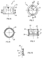
- the ring nut 2 has a ring 21 positioned at the tapered end 2a, as shown in Figure 9.
- the ring 21 has a groove 22 for housing the corresponding rib 11 formed on the flexible axial extensions 7.
- the ring 21 bears four flexible tabs 23 which are inclined towards the end 2b, as shown in Figure 9.
- shoulders 24 extend substantially as far as half way along the length of the ring nut 2 at the bases of the tabs 23 but angularly offset therefrom.
- the tabs 23 and the shoulders 24 are arranged facing one another in pairs, as shown in Figure 7 and Figure 8, respectively.
- two seats 25 are formed in the end wall of the ring nut 2 for the removal of the ring nut 2 from the body 1 with the aid of a tool.
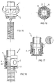
- Figure 11 shows a body 1 and a ring nut 2 in position for engagement on the body 1.
- the arrow indicates the direction in which the ring nut 2 is engaged on the body 1 so as to form the connector for corrugated conduits of the invention.
- Figure 12 shows the ring nut 2 fully fitted on the body 1 so that its fitting end 2b abuts the first intermediate portion 4 of the body.
- the ring nut 2 is restrained in this position by virtue of the engagement achieved between the teeth 8 of the second intermediate portion 5 of the body 1 and the groove 26 of the ring nut 2.
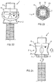
- the tabs 23 are disposed in the slots between the four flexible axial extensions 7. Moreover, as shown in Figure 14, the tabs 23 are disposed adjacent the second inclined plane 16, in a clockwise direction. The third recess 15 is disposed adjacent the second inclined plane 16 in a clockwise direction.
- This position which is shown clearly in Figure 16, represents a preferred state in which the connector for corrugated conduits according to the invention can be sold and, in any case, represents the condition in which the connector is arranged before the insertion of a corrugated conduit.
- the ring nut 2 can be pulled axially so that the tabs 23 pass over the inclined plane 17 and are brought into the first recess 12, achieving a snap-engagement. Moreover, the rib 11 of the head ends of the flexible axial extensions 7 will come into engagement with the corresponding groove 22 of the ring nut 2 and the lip 10 of each resilient extension 7 will come into abutment with the ring 21 to prevent the ring nut 2 from slipping off the body 1.
- This movement which is shown in Figure 19, simultaneously performs two functions: the locking of the corrugated conduit in the connector, and the engagement of a security system.
- tabs 23 are also prevented from rotating anticlockwise, even intentionally, by the shoulder corresponding to the first recess 12 and are prevented from rotating clockwise, unintentionally, by the catch 14 ( Figure 20).
- the connector for corrugated conduits may include a sleeve-like gasket 27 having a flanged end 28.
- the gasket 27 is fitted flush with the end of the corrugated conduit to be inserted in the connector so that the flanged end 28 abuts the edge of the corrugated conduit (Figure 30).
- the corrugated conduit is then inserted in the connector and the flanged end 28 is thus compressed against the cusp 18, improving the PI of the connector ( Figure 31).
- a gasket 29 may be formed integrally with the inside of the connector body 1 in the region of the first intermediate portion 4 and the second intermediate portion 5 ( Figures 32 and 33). Moreover, this gasket 29 is advantageously formed by an annular portion 30, the internal wall of which defines a single plane continuous with the internal wall of the second end 6, and by an annular rim 31 facing inwardly relative to the gasket so as to terminate in the plane identified by the internal wall of the end 3.
- the gasket 29 will preferably be formed by over-moulding or co-injection.
- the connector for corrugated conduits is extremely easy to use since it does not require the use of two hands, the use of a single hand being sufficient. This is particularly useful if the connector has to be fitted, for example, on parts of machines which are difficult to reach.
- the connector has a security system which is easy to use but, at the same time, is effective against unintentional release.
- the connector according to the present invention advantageously has no external openings, thus preventing problems connected with infiltration of dirt and liquids which could cause malfunctioning of the connector and/or of the electrical cables housed therein.
- the connector can be removed from the site of use with the use of tools, by means of the first intermediate portion 4 which has a hexagonal outer shape.
- the security system can also be removed with the aid of tools acting at the level of the seats 25.
- the connector is free of any axial movement when the corrugated conduit is inserted; this results in greater strength, compactness and reliability of the PI leaktightness of the connector.
- the ergonomic grip present on the outer wall of the ring nut further facilitates the operation of the connector by means of the thumb and the index finger of one hand alone.
- the connector for corrugated conduits according to the present invention has been designed and produced to conform to European Norm EN 50086 which regulates the basic requirements for systems and accessories for electrical installations.
- the material used to produce the connector is halogen- and cadmium-free, self-extinguishing PA 66, and the degree of leaktightness without the gasket is PI66 and with the gasket is PI67.
- the tabs 23 may be provided on the body 1 instead of on the ring nut 2, whilst the recesses 12, 13 and 15 and the inclined planes 16 and 17 will consequently be formed on the internal wall of the ring nut 2 which, in addition, will have to have material voids corresponding to the above-described slots between the flexible axial extensions 7.
- tabs 23 and shoulders 24 may vary, for example, there may be two instead of four.
- the stop means 8 and 26 may alternatively be constituted by a ring which projects around the entire external circumference of the second cylindrical portion 5 and which is coupled with a corresponding recess created around the circumference of the internal wall of the ring nut 2.
- the number of flexible axial extensions 7 may vary according to requirements and/or preferences.
- the method of forming the visual "ON-OFF" location mark on the second intermediate portion 5 and the corresponding pointer A on the ring nut 2 may consist of wording and corresponding coloured pointers other than those used in the embodiment shown in the drawings appended hereto.
- the materials usable to construct the connector may also vary according to specific requirements or preferences.
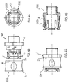
- the body 100 of a connector according to the variant is generally similar in shape to the body 1 shown in Figure 1.
- the body 100 comprises a first end 3, a first intermediate portion 4, a second intermediate portion 5, and a second end 6 comprising flexible axial extensions 7 having two substantially parallel axial edges 117.
- the first portion 4 differs slightly from the first portion of the body 1 of Figure 1 since it preferably has a polygonal shape comprising longer sides alternating with shorter sides.
- the flexible axial extensions 7 of the second end 6 are substantially identical in shape to the flexible axial extensions of the embodiment of Figure 1.
- each flexible axial extension 7 proceeding from the rib 11 towards the second portion 5, there are three projections 114, 115 and 116 arranged along the axis Y-Y of the connector body 100.
- the first projection 114 is positioned substantially in the vicinity of one of the two axial edges 117 of a flexible axial extension 7.
- the second projection 116 is positioned in the vicinity of the centre of the same flexible axial extension.
- the third projection 115 is positioned substantially equidistantly between the projections 114 and 116.
- the first projection 116 is preferably of a less accentuated cylindrical shape than the corresponding second and third projections 114 and 115.
- the first projection 116 moves clockwise from one slot of a flexible axial extension 7 to another, the first projection 116 has a lead-in ramp 120, a substantially flat top 121, and a sufficiently steep wall 122.
- the term "sufficiently steep" will be defined in the following description of the operation of the connector of the invention.
- first, third and second projections 114, 115 and 116 extend, from a predetermined distance from the rib 11, towards the second intermediate portion 5, to meet a transverse projection 118.
- This transverse projection 118 extends throughout the transverse extent of the flexible axial extension 7 from one axial edge 117 to the other axial edge 117.
- a rib 119 extends in an axial direction from the transverse projection 118 and in the vicinity of each of the axial edges 117, as far as the second intermediate end 5 ( Figures 34 and 37).
- Figure 38 is a partial section taken on the line XXXVIII-XXXVIII of Figure 34, in which the inner wall of the body 100 in the vicinity of the first end 3 becomes narrower, creating a shoulder 123.
- a ring nut which can be fitted on the connector body 100 so as to be movable axially and rotationally, is generally indicated 200.
- the ring nut 200 has an outer shape substantially the same as the outer shape of the ring nut 2 described with reference to Figure 6 and parts in common with the ring nut 2 are therefore indicated by the same reference numerals and will not be described further.
- the ring nut 200 has two opposed pointers B, in relief, for indicating the visual "ON-OFF" location marks present on the connector body 100.
- the pointers in fact correspond to the pointer A of Figure 6.
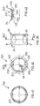
- the ring nut 200 has a first annular band 201 positioned in the region of the end 2b and a second annular band 202 positioned in the region of the end 2a, as shown in Figure 42.
- the first annular band 201 has a groove 207.
- the second annular band 202 has a greater thickness in section than the first annular band 201 and is defined in the vicinity of the end 2a by a thickened outer annular rim 203.
- the second annular band 202 also adjoins the first annular band 201 by means of an inner annular rim 204 having a series of teeth 205 distributed around its circumference.
- teeth 205 there are four of these teeth 205 and they are diametrally opposed, as shown in Figure 40.
- two seats 206 are formed in the vicinity of the end 2a, for the removal of the ring nut 200 from the body 100 with the aid of a tool.
- Figure 43 shows a body 100 and a ring nut 200 positioned for engagement on the body 100.
- the ring nut 200 is fitted on the body 100 with one pointer B aligned with the "OFF" mark.
- the teeth 205 are disposed in the regions of the slots between the flexible axial extensions 7.
- Figure 45 shows the ring nut 200 fully fitted on the body 100 in a manner such that its fitting end 2b abuts the first intermediate portion 4 of the body.
- the ring nut 200 is held in this position by virtue of the engagement achieved between the teeth 8 of the second intermediate portion 5 of the body 1 and the groove 207 of the ring nut 200.
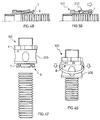
- FIG. 47 shows the connector with a corrugated conduit approaching from the end at which the head ends of the axial extensions 7 are disposed.
- Figure 48 shows a corrugated conduit inserted in the connector of the invention.
- the corrugated conduit can easily be inserted without the teeth 9 of the flexible axial extensions interfering with the channels of the corrugated conduit.
- the ring nut 200 In this position, the ring nut 200 is prevented from slipping off the body 100 and, at the same time, the ring nut holds the flexible axial extensions 7 in a position such that the teeth 9 are engaged in a channel of the corrugated conduit, as already described fully above.
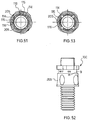
- the ring nut 200 can be rotated clockwise until the pointer B is in the region of the "ON" wording.
- the projection 115 forms a stop which the tooth 205 abuts, preventing further clockwise rotation of the ring nut 200.
- the wall 122 is sufficiently steep to constitute a stop for preventing accidental rotation of the ring-nut in an anticlockwise direction but, at the same time, nevertheless permits anticlockwise rotation as a result of the application of a predetermined force enabling the stop to be passed over.
- the projection 116 constitutes a stop element which can easily be passed over by the tooth 205 as a result of a clockwise rotation of the ring nut 200 but which can be passed over with difficulty by the tooth, only by the application of a predetermined force, as a result of anticlockwise rotation of the ring nut.
- the ring nut 200 cannot be returned to the position of abutment against the first portion 4 of the body 100 by an axial movement, since the tooth 205 is also in abutment against the transverse projection 118 of the body 100.
- the connector for corrugated conduits according to this variant of the invention is provided with security means for preventing accidental release of a corrugated conduit.
- the secure state is advantageously indicated by the visual pointer present on the outer wall of the ring nut 200 which will be disposed in the region of the "ON" mark of the second intermediate portion 5 of the body 100 ( Figure 52).
- the ring nut 200 will move axially into abutment with the first intermediate portion 4 of the body 100 and, as explained above, the flexible axial extensions 7 will be able to bend radially outwardly relative to the body 100 to enable their teeth to be released from engagement with the channels of the corrugated conduit.
- the particular embodiment just described further improves the connector for corrugated conduits according to the present invention, simplifying the structure of the flexible axial extensions 7.
- the teeth 205 are stronger than the tabs 23 described with reference to the previous embodiment precisely in the situation in which it is necessary to use a stronger structure.
- the operations for the preparation and the locking-release of the connector, as well as for the engagement-disengagement of the security means, are further simplified.
- the elimination of the projection 115 also reduces the weight of the structure with the result of achieving greater resilience of the flexible axial extensions 7, which greater resilience may be dictated by particular conditions of use.
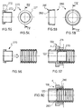
- the connector for corrugated conduits may include a sleeve-like gasket 270 having a flanged end 271, as shown in Figures 54 and 55.
- annular extension 272 extends from the flanged end 271, facing away from the flanged end so as to form a seat 273.
- the gasket 270 When the gasket 270 is fitted in a corrugated conduit such as that shown in Figure 56, its seat 273 can house the base wall of a channel of the corrugated conduit so as to improve the sealing of the gasket against the corrugated conduit.
- the corrugated conduit can be inserted inside the connector body 100 so that the flange 271 abuts the shoulder 123 of the inner wall of the body 100.
- a gasket 280 formed by a sleeve having one end 281 provided with an annular rim 282 facing towards the inside of the gasket so as to form a ledge which abuts the shoulder 123 of the body 100, as shown in Figures 58 and 59.
- a gasket 280 of this type is inserted in the connector body 100 with the outer surface of the annular rim 282 in abutment with the step 123 in the internal wall of the body ( Figure 60).
- the connector for corrugated conduits according to the invention satisfies the requirements referred to in the introductory part of the present description and at the same time overcomes the disadvantages of the connectors for corrugated conduits of the prior art.
- the present invention in fact provides a connector for corrugated conduits which is simple, practical and secure.
Landscapes
- Engineering & Computer Science (AREA)
- General Engineering & Computer Science (AREA)
- Mechanical Engineering (AREA)
- Quick-Acting Or Multi-Walled Pipe Joints (AREA)
Priority Applications (1)
| Application Number | Priority Date | Filing Date | Title |
|---|---|---|---|
| EP20000204263 EP1104865B1 (fr) | 1999-12-01 | 2000-11-30 | Connecteur pour conduits ondulés |
Applications Claiming Priority (3)
| Application Number | Priority Date | Filing Date | Title |
|---|---|---|---|
| EP99830747 | 1999-12-01 | ||
| EP99830747A EP1104866A1 (fr) | 1999-12-01 | 1999-12-01 | Connecteur pour tuyaux ondulés |
| EP20000204263 EP1104865B1 (fr) | 1999-12-01 | 2000-11-30 | Connecteur pour conduits ondulés |
Publications (2)
| Publication Number | Publication Date |
|---|---|
| EP1104865A1 true EP1104865A1 (fr) | 2001-06-06 |
| EP1104865B1 EP1104865B1 (fr) | 2005-09-28 |
Family
ID=26072881
Family Applications (1)
| Application Number | Title | Priority Date | Filing Date |
|---|---|---|---|
| EP20000204263 Expired - Lifetime EP1104865B1 (fr) | 1999-12-01 | 2000-11-30 | Connecteur pour conduits ondulés |
Country Status (1)
| Country | Link |
|---|---|
| EP (1) | EP1104865B1 (fr) |
Cited By (3)
| Publication number | Priority date | Publication date | Assignee | Title |
|---|---|---|---|---|
| DE10158114A1 (de) * | 2001-11-27 | 2003-06-26 | Kirchner Fraenk Rohr | Anschlussvorrichtung für Wellschauchleitung und Leitungssystem |
| EP4332420A1 (fr) * | 2022-08-29 | 2024-03-06 | TI Automotive (Fuldabrück) GmbH | Conduite de fluide dotée d'un tube ondulé acheminant le fluide |
| EP4397897A1 (fr) * | 2023-01-04 | 2024-07-10 | Deere & Company | Ensemble de tuyau de raccord coulissant |
Citations (4)
| Publication number | Priority date | Publication date | Assignee | Title |
|---|---|---|---|---|
| US4328979A (en) * | 1979-07-18 | 1982-05-11 | Kurt Stoll | Adaptor connecting piece for conduits designed to carry gaseous or liquid media |
| US4440425A (en) * | 1978-02-06 | 1984-04-03 | Indian Head Inc. | Flexible conduit system |
| US5356181A (en) * | 1992-10-15 | 1994-10-18 | The Furukawa Electric Co., Ltd. | Jointing device for a corrugated flexible conduit |
| US5884943A (en) * | 1995-07-22 | 1999-03-23 | Gardena Kress + Kastner Gmbh | Sleeve of a gardening tool, particularly coupling sleeve of a quick hose coupling |
-
2000
- 2000-11-30 EP EP20000204263 patent/EP1104865B1/fr not_active Expired - Lifetime
Patent Citations (4)
| Publication number | Priority date | Publication date | Assignee | Title |
|---|---|---|---|---|
| US4440425A (en) * | 1978-02-06 | 1984-04-03 | Indian Head Inc. | Flexible conduit system |
| US4328979A (en) * | 1979-07-18 | 1982-05-11 | Kurt Stoll | Adaptor connecting piece for conduits designed to carry gaseous or liquid media |
| US5356181A (en) * | 1992-10-15 | 1994-10-18 | The Furukawa Electric Co., Ltd. | Jointing device for a corrugated flexible conduit |
| US5884943A (en) * | 1995-07-22 | 1999-03-23 | Gardena Kress + Kastner Gmbh | Sleeve of a gardening tool, particularly coupling sleeve of a quick hose coupling |
Cited By (6)
| Publication number | Priority date | Publication date | Assignee | Title |
|---|---|---|---|---|
| DE10158114A1 (de) * | 2001-11-27 | 2003-06-26 | Kirchner Fraenk Rohr | Anschlussvorrichtung für Wellschauchleitung und Leitungssystem |
| DE10158114B4 (de) * | 2001-11-27 | 2011-03-17 | Fränkische Rohrwerke Gebr. Kirchner GmbH + Co. KG | Anschlussvorrichtung für Wellschauchleitung und Leitungssystem |
| EP4332420A1 (fr) * | 2022-08-29 | 2024-03-06 | TI Automotive (Fuldabrück) GmbH | Conduite de fluide dotée d'un tube ondulé acheminant le fluide |
| WO2024046700A1 (fr) * | 2022-08-29 | 2024-03-07 | TI Automotive (Fuldabrück) GmbH | Conduite de fluide comprenant un tuyau ondulé de guidage de fluide |
| EP4397897A1 (fr) * | 2023-01-04 | 2024-07-10 | Deere & Company | Ensemble de tuyau de raccord coulissant |
| US12578046B2 (en) | 2023-01-04 | 2026-03-17 | Deere & Company | Air conveyance quick connect fitting |
Also Published As
| Publication number | Publication date |
|---|---|
| EP1104865B1 (fr) | 2005-09-28 |
Similar Documents
| Publication | Publication Date | Title |
|---|---|---|
| EP1517075A2 (fr) | Dispositif de connexion | |
| US5132493A (en) | Device for connecting non-metallic sheathed cable to an electric box | |
| US5568946A (en) | Squeeze-to-release quick connector with snap-in retainer | |
| EP0317249B1 (fr) | Raccord tournant pour conduites tubulaires | |
| EP2848280A1 (fr) | Connecteur rapide pour conduite de fluide avec verrouillage par bras elastiques intégrales au bouton d'ouverture | |
| EP0663557B1 (fr) | Améliorations rélatives à des raccords de tuyaux | |
| GB2236567A (en) | A hose coupling | |
| GB2265428A (en) | Couplings for corrugated conduits | |
| JPH02212693A (ja) | 管継手スリーブ | |
| KR100701099B1 (ko) | 접속기구 | |
| EP0667480A1 (fr) | Perfectionnement dans ou aux connecteurs de tube | |
| WO1998027374A1 (fr) | Raccord rapide a liberation par poussee | |
| US20110025042A1 (en) | Removal Tool | |
| EP1104865B1 (fr) | Connecteur pour conduits ondulés | |
| US5028080A (en) | Quick connect coupling | |
| JPH02290096A (ja) | ケーブル取付構造 | |
| EP1104866A1 (fr) | Connecteur pour tuyaux ondulés | |
| JP5054956B2 (ja) | 管継手 | |
| EP0200339A2 (fr) | Raccords pour tuyaux | |
| WO1998004865A1 (fr) | Dispositif de raccord ameliore | |
| US20240175529A1 (en) | Emt compression slide over coupling three piece assembly | |
| EP1113553B1 (fr) | Raccord étanche | |
| WO1988002085A1 (fr) | Raccord de tuyau | |
| JP2004364469A (ja) | 閉鎖キャップ | |
| CN121464290A (zh) | 管连接器 |
Legal Events
| Date | Code | Title | Description |
|---|---|---|---|
| PUAI | Public reference made under article 153(3) epc to a published international application that has entered the european phase |
Free format text: ORIGINAL CODE: 0009012 |
|
| AK | Designated contracting states |
Kind code of ref document: A1 Designated state(s): AT BE CH CY DE DK ES FI FR GB GR IE IT LI LU MC NL PT SE TR |
|
| AX | Request for extension of the european patent |
Free format text: AL;LT;LV;MK;RO;SI |
|
| 17P | Request for examination filed |
Effective date: 20010525 |
|
| AKX | Designation fees paid |
Free format text: AT BE CH CY DE DK ES FI FR GB GR IE IT LI LU MC NL PT SE TR |
|
| 17Q | First examination report despatched |
Effective date: 20040810 |
|
| GRAP | Despatch of communication of intention to grant a patent |
Free format text: ORIGINAL CODE: EPIDOSNIGR1 |
|
| GRAS | Grant fee paid |
Free format text: ORIGINAL CODE: EPIDOSNIGR3 |
|
| GRAA | (expected) grant |
Free format text: ORIGINAL CODE: 0009210 |
|
| AK | Designated contracting states |
Kind code of ref document: B1 Designated state(s): AT BE CH CY DE DK ES FI FR GB GR IE IT LI LU MC NL PT SE TR |
|
| PG25 | Lapsed in a contracting state [announced via postgrant information from national office to epo] |
Ref country code: AT Free format text: LAPSE BECAUSE OF FAILURE TO SUBMIT A TRANSLATION OF THE DESCRIPTION OR TO PAY THE FEE WITHIN THE PRESCRIBED TIME-LIMIT Effective date: 20050928 Ref country code: LI Free format text: LAPSE BECAUSE OF FAILURE TO SUBMIT A TRANSLATION OF THE DESCRIPTION OR TO PAY THE FEE WITHIN THE PRESCRIBED TIME-LIMIT Effective date: 20050928 Ref country code: FI Free format text: LAPSE BECAUSE OF FAILURE TO SUBMIT A TRANSLATION OF THE DESCRIPTION OR TO PAY THE FEE WITHIN THE PRESCRIBED TIME-LIMIT Effective date: 20050928 Ref country code: NL Free format text: LAPSE BECAUSE OF FAILURE TO SUBMIT A TRANSLATION OF THE DESCRIPTION OR TO PAY THE FEE WITHIN THE PRESCRIBED TIME-LIMIT Effective date: 20050928 Ref country code: CH Free format text: LAPSE BECAUSE OF FAILURE TO SUBMIT A TRANSLATION OF THE DESCRIPTION OR TO PAY THE FEE WITHIN THE PRESCRIBED TIME-LIMIT Effective date: 20050928 |
|
| RAP1 | Party data changed (applicant data changed or rights of an application transferred) |
Owner name: LEGRAND S.P.A. |
|
| REG | Reference to a national code |
Ref country code: GB Ref legal event code: FG4D |
|
| REG | Reference to a national code |
Ref country code: CH Ref legal event code: EP |
|
| REG | Reference to a national code |
Ref country code: IE Ref legal event code: FG4D |
|
| REF | Corresponds to: |
Ref document number: 60022846 Country of ref document: DE Date of ref document: 20051103 Kind code of ref document: P |
|
| PG25 | Lapsed in a contracting state [announced via postgrant information from national office to epo] |
Ref country code: LU Free format text: LAPSE BECAUSE OF NON-PAYMENT OF DUE FEES Effective date: 20051130 Ref country code: MC Free format text: LAPSE BECAUSE OF NON-PAYMENT OF DUE FEES Effective date: 20051130 Ref country code: CY Free format text: LAPSE BECAUSE OF FAILURE TO SUBMIT A TRANSLATION OF THE DESCRIPTION OR TO PAY THE FEE WITHIN THE PRESCRIBED TIME-LIMIT Effective date: 20051130 Ref country code: IE Free format text: LAPSE BECAUSE OF NON-PAYMENT OF DUE FEES Effective date: 20051130 |
|
| PG25 | Lapsed in a contracting state [announced via postgrant information from national office to epo] |
Ref country code: SE Free format text: LAPSE BECAUSE OF FAILURE TO SUBMIT A TRANSLATION OF THE DESCRIPTION OR TO PAY THE FEE WITHIN THE PRESCRIBED TIME-LIMIT Effective date: 20051228 Ref country code: DK Free format text: LAPSE BECAUSE OF FAILURE TO SUBMIT A TRANSLATION OF THE DESCRIPTION OR TO PAY THE FEE WITHIN THE PRESCRIBED TIME-LIMIT Effective date: 20051228 |
|
| PG25 | Lapsed in a contracting state [announced via postgrant information from national office to epo] |
Ref country code: DE Free format text: LAPSE BECAUSE OF FAILURE TO SUBMIT A TRANSLATION OF THE DESCRIPTION OR TO PAY THE FEE WITHIN THE PRESCRIBED TIME-LIMIT Effective date: 20051229 |
|
| REG | Reference to a national code |
Ref country code: GR Ref legal event code: EP Ref document number: 20050403706 Country of ref document: GR |
|
| REG | Reference to a national code |
Ref country code: ES Ref legal event code: FG2A Ref document number: 2246212 Country of ref document: ES Kind code of ref document: T3 |
|
| NLV1 | Nl: lapsed or annulled due to failure to fulfill the requirements of art. 29p and 29m of the patents act | ||
| REG | Reference to a national code |
Ref country code: CH Ref legal event code: PL |
|
| ET | Fr: translation filed | ||
| PLBE | No opposition filed within time limit |
Free format text: ORIGINAL CODE: 0009261 |
|
| STAA | Information on the status of an ep patent application or granted ep patent |
Free format text: STATUS: NO OPPOSITION FILED WITHIN TIME LIMIT |
|
| 26N | No opposition filed |
Effective date: 20060629 |
|
| REG | Reference to a national code |
Ref country code: IE Ref legal event code: MM4A |
|
| PGFP | Annual fee paid to national office [announced via postgrant information from national office to epo] |
Ref country code: TR Payment date: 20091117 Year of fee payment: 10 |
|
| PGFP | Annual fee paid to national office [announced via postgrant information from national office to epo] |
Ref country code: PT Payment date: 20091110 Year of fee payment: 10 |
|
| PGFP | Annual fee paid to national office [announced via postgrant information from national office to epo] |
Ref country code: GB Payment date: 20091102 Year of fee payment: 10 |
|
| PGFP | Annual fee paid to national office [announced via postgrant information from national office to epo] |
Ref country code: GR Payment date: 20091026 Year of fee payment: 10 |
|
| REG | Reference to a national code |
Ref country code: PT Ref legal event code: MM4A Free format text: LAPSE DUE TO NON-PAYMENT OF FEES Effective date: 20110531 |
|
| GBPC | Gb: european patent ceased through non-payment of renewal fee |
Effective date: 20101130 |
|
| PG25 | Lapsed in a contracting state [announced via postgrant information from national office to epo] |
Ref country code: GR Free format text: LAPSE BECAUSE OF NON-PAYMENT OF DUE FEES Effective date: 20110602 Ref country code: PT Free format text: LAPSE BECAUSE OF NON-PAYMENT OF DUE FEES Effective date: 20110531 |
|
| PG25 | Lapsed in a contracting state [announced via postgrant information from national office to epo] |
Ref country code: GB Free format text: LAPSE BECAUSE OF NON-PAYMENT OF DUE FEES Effective date: 20101130 |
|
| PG25 | Lapsed in a contracting state [announced via postgrant information from national office to epo] |
Ref country code: TR Free format text: LAPSE BECAUSE OF NON-PAYMENT OF DUE FEES Effective date: 20101130 |
|
| REG | Reference to a national code |
Ref country code: FR Ref legal event code: PLFP Year of fee payment: 16 |
|
| PGFP | Annual fee paid to national office [announced via postgrant information from national office to epo] |
Ref country code: FR Payment date: 20151023 Year of fee payment: 16 Ref country code: ES Payment date: 20151110 Year of fee payment: 16 Ref country code: BE Payment date: 20151022 Year of fee payment: 16 |
|
| PG25 | Lapsed in a contracting state [announced via postgrant information from national office to epo] |
Ref country code: BE Free format text: LAPSE BECAUSE OF NON-PAYMENT OF DUE FEES Effective date: 20161130 |
|
| PGFP | Annual fee paid to national office [announced via postgrant information from national office to epo] |
Ref country code: IT Payment date: 20161025 Year of fee payment: 17 |
|
| REG | Reference to a national code |
Ref country code: FR Ref legal event code: ST Effective date: 20170731 |
|
| PG25 | Lapsed in a contracting state [announced via postgrant information from national office to epo] |
Ref country code: FR Free format text: LAPSE BECAUSE OF NON-PAYMENT OF DUE FEES Effective date: 20161130 |
|
| REG | Reference to a national code |
Ref country code: BE Ref legal event code: MM Effective date: 20161130 |
|
| PG25 | Lapsed in a contracting state [announced via postgrant information from national office to epo] |
Ref country code: ES Free format text: LAPSE BECAUSE OF FAILURE TO SUBMIT A TRANSLATION OF THE DESCRIPTION OR TO PAY THE FEE WITHIN THE PRESCRIBED TIME-LIMIT Effective date: 20050928 |
|
| REG | Reference to a national code |
Ref country code: ES Ref legal event code: FD2A Effective date: 20180627 |
|
| PG25 | Lapsed in a contracting state [announced via postgrant information from national office to epo] |
Ref country code: ES Free format text: LAPSE BECAUSE OF FAILURE TO SUBMIT A TRANSLATION OF THE DESCRIPTION OR TO PAY THE FEE WITHIN THE PRESCRIBED TIME-LIMIT Effective date: 20161201 |
|
| PG25 | Lapsed in a contracting state [announced via postgrant information from national office to epo] |
Ref country code: IT Free format text: LAPSE BECAUSE OF NON-PAYMENT OF DUE FEES Effective date: 20171130 |
|
| RIC2 | Information provided on ipc code assigned after grant |
Ipc: F16L 25/00 20060101AFI20010308BHEP |