EP1104867A2 - Vorrichtung zum automatischen Zuführen von Schmiermittel - Google Patents
Vorrichtung zum automatischen Zuführen von Schmiermittel Download PDFInfo
- Publication number
- EP1104867A2 EP1104867A2 EP00102195A EP00102195A EP1104867A2 EP 1104867 A2 EP1104867 A2 EP 1104867A2 EP 00102195 A EP00102195 A EP 00102195A EP 00102195 A EP00102195 A EP 00102195A EP 1104867 A2 EP1104867 A2 EP 1104867A2
- Authority
- EP
- European Patent Office
- Prior art keywords
- lubricating oil
- flanger
- pump
- pouch
- feeding apparatus
- Prior art date
- Legal status (The legal status is an assumption and is not a legal conclusion. Google has not performed a legal analysis and makes no representation as to the accuracy of the status listed.)
- Granted
Links
- 239000010687 lubricating oil Substances 0.000 title claims abstract description 119
- 210000002445 nipple Anatomy 0.000 claims abstract description 9
- 230000001174 ascending effect Effects 0.000 claims abstract description 6
- 238000001125 extrusion Methods 0.000 claims abstract description 4
- 238000005086 pumping Methods 0.000 claims abstract description 4
- 238000003556 assay Methods 0.000 claims description 5
- 238000005192 partition Methods 0.000 claims description 4
- 239000003638 chemical reducing agent Substances 0.000 claims description 3
- 239000004973 liquid crystal related substance Substances 0.000 claims description 2
- 238000007789 sealing Methods 0.000 claims description 2
- 238000000926 separation method Methods 0.000 abstract description 6
- 239000004519 grease Substances 0.000 description 13
- 239000003921 oil Substances 0.000 description 3
- 238000003912 environmental pollution Methods 0.000 description 2
- 238000005461 lubrication Methods 0.000 description 2
- 238000007726 management method Methods 0.000 description 2
- 229910000831 Steel Inorganic materials 0.000 description 1
- 238000006243 chemical reaction Methods 0.000 description 1
- 238000010276 construction Methods 0.000 description 1
- 230000008602 contraction Effects 0.000 description 1
- 230000003247 decreasing effect Effects 0.000 description 1
- 230000006866 deterioration Effects 0.000 description 1
- 238000007599 discharging Methods 0.000 description 1
- 230000000694 effects Effects 0.000 description 1
- 230000020169 heat generation Effects 0.000 description 1
- 230000007774 longterm Effects 0.000 description 1
- 238000000034 method Methods 0.000 description 1
- 239000010959 steel Substances 0.000 description 1
- 230000037303 wrinkles Effects 0.000 description 1
Images





Classifications
-
- F—MECHANICAL ENGINEERING; LIGHTING; HEATING; WEAPONS; BLASTING
- F16—ENGINEERING ELEMENTS AND UNITS; GENERAL MEASURES FOR PRODUCING AND MAINTAINING EFFECTIVE FUNCTIONING OF MACHINES OR INSTALLATIONS; THERMAL INSULATION IN GENERAL
- F16N—LUBRICATING
- F16N13/00—Lubricating-pumps
-
- F—MECHANICAL ENGINEERING; LIGHTING; HEATING; WEAPONS; BLASTING
- F16—ENGINEERING ELEMENTS AND UNITS; GENERAL MEASURES FOR PRODUCING AND MAINTAINING EFFECTIVE FUNCTIONING OF MACHINES OR INSTALLATIONS; THERMAL INSULATION IN GENERAL
- F16N—LUBRICATING
- F16N11/00—Arrangements for supplying grease from a stationary reservoir or the equivalent in or on the machine or member to be lubricated; Grease cups
- F16N11/08—Arrangements for supplying grease from a stationary reservoir or the equivalent in or on the machine or member to be lubricated; Grease cups with mechanical drive, other than directly by springs or weights
Definitions
- the present invention relates to an automatic lubricating oil feeding apparatus which automatically feeds lubricating oil at predetermined intervals to parts requiring the lubricating oil such as rotary driving parts of various kinds of machines where bearings are installed.
- the present invention relates to an automatic lubricating oil feeding apparatus which can easily conquer the resistance of tube passages of machine elements where bearings are installed and thus facilitate the lubricating oil feeding to the machine elements by forming a lubricating oil discharge structure having a mechanical type vertical suction pump structure.
- One among the conventional apparatuses is a grease gun for manually feeding the lubricating oil at specified times.
- managements of feeding times, parts to be fed with the lubricating oil, security of feeding manpower, etc. should be thoroughly performed. If such managements are not accurately performed, this causes an early wear or damage of the bearings, and thus the whole machine may be shocked.
- This oil-separation phenomenon causes the oil to slip out of a lubricating oil pouch as a specified period of time elapses, and only other components of the grease remain in the pouch. Accordingly, the grease is hardened as much as that the grease cannot be pushed out any more by the elasticity of the spring, and this causes the performance of the lubricating oil feeding apparatus to be degraded and the feeding of the grease to be impossible, thereby inviting the damage of the bearing.
- gas generation type and electrochemical type automatic lubricating oil feeding apparatuses have been proposed.
- the gas generation type apparatus uses the chemical reaction
- the electrochemical type apparatus uses a battery.
- the grease suction phenomenon in one lot can be avoided.
- the oil-separation phenomenon also occurs as in the spring type lubricating oil feeding apparatus.
- the interior of the main case is formed so that the pump is placed between an exit of the lubricating oil pouch and the nipple, and the lubricating oil is sucked and extruded by ascent and descent of the flanger of the pump.
- a motor for driving the pump In the main case is installed a motor for driving the pump.
- FIG. 1 is a front view illustrating the structure of the lubricating oil feeding apparatus according to the present invention.
- FIG. 2 is a sectional view of FIG. 1.
- FIG. 5 is a plan view of a lubricating oil pump in the lubricating oil feeding apparatus according to the present invention.
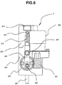
- FIG. 6 is a front view of FIG. 5.
- FIG. 8 is a view illustrating a battery case.
- FIG. 9 is a sectional view of a lubricating oil pump according to the present invention explaining the state of the lubricating oil suction.
- FIG. 10 is a sectional view of a lubricating oil pump explaining the state of the lubricating oil extrusion.
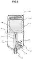
- the automatic lubricating oil feeding apparatus comprises a main case 1 positioned on a lower portion of the apparatus, a top cover 2 screw-fastened to an upper portion of the main case, and a pump 3.
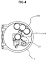
- the main case 1 includes a nipple 110 fastened to the main case along a central axis of the main case 1, a plurality of manipulation switches and a large-scaled liquid crystal display (LCD) formed on one side of the main case 1. Also, a fastening screw is formed on an outer periphery of the upper portion of the main case, and a partition 114, which has a through hole formed thereon for supporting a battery case 112 and an upper portion of the pump 3, is secured to the upper portion of the main case 1 to close an upper opening of the main case 1.
- the main case also has an inner space where a motor and a battery required for discharging lubricating oil, and the pump actually performing the lubricating oil discharge is installed.
- the top cover 2 is cylindrical, and has a screw formed on an inner periphery of a lower portion thereof, a pressure spring 210 and a pressure plate 212 formed on an upper portion of its inside, and a lubricating oil pouch 220 built therein to receive an elastic force from the pressure spring and the pressure plate.
- the lubricating oil pouch has the shape of wrinkles to facilitate its contraction under the pressure of the pressure spring and the pressure plate.
- the pressure spring assists the outflow of the lubricating oil by contracting the lubricating oil pouch so that the lubricating oil is extruded from the lubricating oil pouch by the suction force provided from the pump while the lubricating oil pouch maintains its horizontality without being inclined.
- the pump 3 comprises an upper body 310, a lower body 320, and a flanger assay 330 inserted between the upper body and the lower body.
- the upper body 310 has a tap hole 312 formed on an upper end of the upper body for being screw-engaged with a gateway 222 of the lubricating oil pouch 220, and a passage 316 formed extending from the tap hole for receiving therein a ball valve 314 acting as a check valve.
- the lower body 320 has a passage 326 formed thereon to be concentric with the passage 316 of the upper body, an open type elongated hole 322 having the form of a slit and formed on one side of the lower body 320, and a sheet 328 inserted below the elongated hole 322 for screw-engaging with a shaft 341 for fastening a worm wheel 340.
- the flanger assay 330 has a cylindrical shape, and ascends and descends in the passages 316 and 326 of the upper body 310 and the lower body 320.
- a protrusion 334 is formed on one side of a flanger shaft 332, and a through hole 333 is formed through the flanger shaft 332 in a manner that the through hole does not penetrate through the flanger shaft and the lower portion of the flanger shaft is closed.
- An exhaust hole 335 is formed on the lower portion of the flanger shaft 332 so as to cross-penetrate to the through hole 333.
- On the upper and lower portions of the flanger shaft 332 is formed a sealing 339 for preventing the leakage of pressure.
- the upper body 310 and the lower body 320 communicates with each other through the passages 316 and 326, the flanger shaft 332 of the flanger assay 330 is inserted into the passages, and the protrusion 334 of the flanger shaft is protruded into the elongated hole 322.
- a spring 318 is inserted between the ball valve 314 and the upper portion of the flanger shaft 332 to enable the ball valve to act as a check valve.
- a motor 350 with a built-in speed reducer is fixed to the one side of the body, and a shaft 341 for fixing the worm wheel 340 is secured to the sheet 328 of the lower body 320.
- a worm gear 432 fixed to a shaft of the speed reducer is engaged with the worm wheel 340.
- an eccentric link connection sheet 343 is formed on one side of the worm wheel 340, and a link 345 for connecting the link connection sheet 343 and the protrusion 334 of the flanger shaft is secured to the sheet via a lever 338.
- the link is fastened by bolts 347 and 348.
- the pump 3 as constructed above is secured between the nipple 110 and the through hole of the partition 114 in the main case 1.
- the battery case 112 detachably receives a small-capacity battery.
- the motor 350 is driven by a control means (not illustrated) , and the worm gear 342 is rotated by the driving force of the motor 350.
- the position where the lubricating oil is sucked at maximum is where the link connection sheet 343 of the worm wheel 340 reaches its lowest point.
- the suction amount of the lubricating oil is determined by the volume provided by the passage 316 and the descending stroke of the flanger.
- the sucked lubricating oil is compressed and moves downward along the through hole 333 as the link connection sheet 343 moves to its uppermost position by the continuous rotation of the work wheel 340, and thus the flanger shaft 332 ascends.
- the ball valve 314 prevents the reverse flow of the lubricating oil, and the tube 337 intercepts a reverse inflow of the discharged lubrication oil.
- the lubrication oil is once discharged.
- the pump 3 which sucks and discharges the lubricating oil as described above transfers a specified volume of the lubricating oil, and thus the insufficient feeding or overfeeding of the lubricating oil can be thoroughly eliminated.
- the lubricating oil pouch 220 loses the specified volume of the lubricating oil contained therein, and at this time, the pouch 220 is contracted by the pressure of the pressure spring 210 and the pressure plate 212. Even when the residual quantity of the lubricating oil is decreased by long-term use of the apparatus, the lubricating oil pouch 220 shrinks with its horizontality maintained, thereby not obstructing the suction operation of the lubricating oil.
- the replacement of the lubricating oil is achieved by loosing the top cover 2, separating the gateway 222 therefrom, and then inserting a new lubricating oil pouch 220.
- the replacement of the battery is achieved by separating and extracting the battery case 112 by loosing the clip secured to the partition 114, exchanging the dissipated battery for a new one, and fastening them in a reverse order.
- the nipple is made of steel since it is required to be firmly formed considering the vibration-proof characteristic.
- the oil-separation phenomenon can be removed even if the apparatus is used for a long time by effecting a pumping operation for the suction and discharge of lubricating oil by the pressure of a flanger ascending and descending by a mechanical driving force, and thus by not applying a high pressure to a lubricating oil pouch.
- an accurate amount of lubricating oil can be fed by extruding a fixed quantity of lubricating oil by the stroke of a flanger, and thus a harmful influence upon the machine elements due to the insufficient feeding or overfeeding of the lubricating oil can be prevented as well as the resistance of tube passages can be overcome by a high discharge pressure by a flanger to facilitate the lubricating oil feeding to the machine elements.
- the replacement work of the lubricating oil or the battery can be facilitated by exchanging only the lubricating oil pouch or the battery, and this also results in the reduction of the environmental pollution.
Landscapes
- Engineering & Computer Science (AREA)
- General Engineering & Computer Science (AREA)
- Mechanical Engineering (AREA)
- Details Of Reciprocating Pumps (AREA)
- General Details Of Gearings (AREA)
- Lubrication Of Internal Combustion Engines (AREA)
- Rotary Pumps (AREA)
Applications Claiming Priority (2)
| Application Number | Priority Date | Filing Date | Title |
|---|---|---|---|
| KR9954507 | 1999-12-02 | ||
| KR1019990054507A KR100282128B1 (ko) | 1999-12-02 | 1999-12-02 | 윤활유 자동 공급 장치 |
Publications (3)
| Publication Number | Publication Date |
|---|---|
| EP1104867A2 true EP1104867A2 (de) | 2001-06-06 |
| EP1104867A3 EP1104867A3 (de) | 2002-06-26 |
| EP1104867B1 EP1104867B1 (de) | 2006-09-06 |
Family
ID=37055731
Family Applications (1)
| Application Number | Title | Priority Date | Filing Date |
|---|---|---|---|
| EP00102195A Expired - Lifetime EP1104867B1 (de) | 1999-12-02 | 2000-02-09 | Vorrichtung zum automatischen Zuführen von Schmiermittel |
Country Status (4)
| Country | Link |
|---|---|
| US (1) | US6354816B1 (de) |
| EP (1) | EP1104867B1 (de) |
| KR (1) | KR100282128B1 (de) |
| DE (1) | DE60030529T2 (de) |
Cited By (7)
| Publication number | Priority date | Publication date | Assignee | Title |
|---|---|---|---|---|
| GB2424457A (en) * | 2005-03-24 | 2006-09-27 | Aes Eng Ltd | A seal support system with discharging means |
| WO2009068135A1 (de) * | 2007-11-29 | 2009-06-04 | Lincoln Gmbh | Schmierstoffgeber |
| WO2014076315A3 (en) * | 2012-11-19 | 2014-07-10 | Castrol Limited | Fluid reservoir system |
| US9878822B2 (en) | 2012-11-19 | 2018-01-30 | Castrol Limited | Replaceable fluid container |
| US9938867B2 (en) | 2012-11-19 | 2018-04-10 | Castrol Limited | Cartridge and system for replenishing fluid in an apparatus |
| WO2020187501A1 (de) * | 2019-03-15 | 2020-09-24 | Perma-Tec Gmbh & Co. Kg | Schmierstoffspender |
| WO2020187500A1 (de) * | 2019-03-15 | 2020-09-24 | Perma-Tec Gmbh & Co. Kg | Schmierstoffspender |
Families Citing this family (29)
| Publication number | Priority date | Publication date | Assignee | Title |
|---|---|---|---|---|
| NL1013446C2 (nl) * | 1999-11-01 | 2001-05-02 | Skf Eng & Res Centre Bv | Inrichting in een smeermiddelpomp. |
| KR100282129B1 (ko) * | 1999-12-02 | 2001-02-15 | 양윤종 | 마이컴을 이용한 윤활유 자동공급방법 |
| DE50003667D1 (de) * | 2000-12-07 | 2003-10-16 | Perma Tec Gmbh & Co Kg | Schmierstoffspender |
| CA2488809A1 (en) * | 2002-06-12 | 2003-12-24 | Lubriquip, Inc. | Automatic lubrication system |
| DE10234881B4 (de) * | 2002-06-19 | 2008-12-04 | Perma-Tec Gmbh & Co Kg | Dosiervorrichtung für Schmierstoff |
| US7152712B2 (en) * | 2003-05-07 | 2006-12-26 | Honeywell International, Inc. | Control moment gyro spin bearing lubricant delivery system and method |
| US20060060425A1 (en) * | 2004-09-17 | 2006-03-23 | Curtis Richardson | Air/oil mist lubrication system and method of use |
| KR100765472B1 (ko) * | 2005-12-20 | 2007-10-09 | 아륭기공(주) | 그리스카트리지 및 그 그리스카트리지를 갖는 그리스공급장치 |
| US20070144834A1 (en) * | 2005-12-28 | 2007-06-28 | Eugene Matzan | Controlling lubrication of moving bodies such as bearings of electric motors |
| US7828119B1 (en) | 2006-01-13 | 2010-11-09 | Schirado Richard M | Grease gun applicator system |
| JP4892258B2 (ja) * | 2006-03-17 | 2012-03-07 | 本田技研工業株式会社 | 船舶用ドライブシャフトの軸受け構造 |
| KR100858360B1 (ko) * | 2008-03-17 | 2008-09-11 | 주식회사 케이.엘.티 | 역방향 가압식 윤활유 자동공급장치 |
| DE102009022707B4 (de) * | 2009-03-05 | 2014-03-27 | Perma-Tec Gmbh & Co. Kg | Schmierstoffspender |
| EP2472109B1 (de) * | 2011-01-04 | 2016-06-29 | Siemens Aktiengesellschaft | Behälter für ein Schmiermittel |
| ES2437176B1 (es) * | 2012-05-31 | 2014-07-03 | Dobgir, S.L. | Aerogenerador de eje vertical |
| KR101409983B1 (ko) * | 2013-06-03 | 2014-06-19 | 경남정보대학교 산학협력단 | 플런저 이동식 윤활유 자동 주유장치 |
| KR101546379B1 (ko) * | 2014-03-07 | 2015-08-21 | 주식회사 케이엘티 | 윤활유 주입기 |
| GB2536916B (en) * | 2015-03-31 | 2018-09-26 | Skf Ab | Lubricating device with a control unit for operating the lubricating pump |
| KR101903184B1 (ko) * | 2016-11-30 | 2018-10-01 | 주식회사 케이엘티 | 윤활유 주입 장치 |
| CN114087516B (zh) * | 2020-08-25 | 2026-03-17 | 郑州奥特科技有限公司 | 一种泵头组件及润滑装置及集中润滑系统 |
| CN112097089B (zh) * | 2020-09-01 | 2025-03-28 | 济南赛邦石油化学有限公司 | 一种冲床用润滑油自动添加机构 |
| KR102514292B1 (ko) | 2021-04-29 | 2023-03-27 | 배휘찬 | 그리스 공급 장치 |
| DE102021129977B4 (de) * | 2021-11-17 | 2025-12-04 | Perma-Tec Gmbh & Co. Kg | Schmierstoffspender |
| US11898700B2 (en) * | 2022-03-07 | 2024-02-13 | Suburban Manufacturing, Llc | Machine lubrication system |
| CN115111515B (zh) * | 2022-07-15 | 2025-11-21 | 固安乾宇嘉润滑设备有限公司 | 一种集中油路双线泵油装置 |
| CN117631524A (zh) * | 2022-08-09 | 2024-03-01 | 斯凯孚公司 | 润滑器控制方法 |
| CN115748655B (zh) * | 2022-11-30 | 2023-06-20 | 北京振冲工程机械有限公司 | 一种液压振冲器 |
| WO2024159074A2 (en) | 2023-01-27 | 2024-08-02 | Vgp Ipco Llc | Reusable or refillable container for dispensing motor oil |
| CN116378796A (zh) * | 2023-04-06 | 2023-07-04 | 浙江吉利控股集团有限公司 | 一种用于混合动力车辆的发动机的供油系统及车辆 |
Family Cites Families (15)
| Publication number | Priority date | Publication date | Assignee | Title |
|---|---|---|---|---|
| US4034831A (en) * | 1973-03-08 | 1977-07-12 | Oil-Rite Corporation | Oiler assembly |
| JPS51127971A (en) * | 1975-04-30 | 1976-11-08 | Hitachi Ltd | Automatic fuel supply device |
| US4284174A (en) * | 1979-04-18 | 1981-08-18 | Avco Corporation | Emergency oil/mist system |
| DE3336269A1 (de) * | 1983-10-05 | 1985-04-18 | Carl Edelmann Gmbh, 7920 Heidenheim | Innenbeutelpackung mit verschliessbarem ausgiessstutzen |
| US4512292A (en) * | 1983-12-19 | 1985-04-23 | Brunswick Corporation | Accessory gear drive for a two-cycle engine |
| US5050707A (en) * | 1990-01-22 | 1991-09-24 | Arne Wilhelmsen | Automatic oiling device |
| WO1993010391A1 (en) | 1991-11-22 | 1993-05-27 | Denis Arthur John Patterson | A dispensing device |
| DE4209776A1 (de) * | 1992-03-26 | 1993-09-30 | Satzinger Gmbh & Co | Schmierstoffspender zur gasgesteuerten Abgabe eines Schmiermittels an eine Maschine |
| GB2271391B (en) * | 1992-10-12 | 1995-08-02 | Hornche Trading Co Ltd | Automatic grease dispenser |
| KR0110998Y1 (en) | 1992-12-01 | 1997-12-22 | Hankuk Lubrication Technology | Device for supplying lubrication oil |
| DE4241073C1 (de) | 1992-12-05 | 1994-06-01 | Satzinger Gmbh & Co | Apparat für die dosierte Abgabe von einem Fluid, insbesondere von einem Schmiermittelfluid |
| DE4422407C2 (de) * | 1994-06-29 | 2001-07-05 | Perma Tec Gmbh & Co Kg | Schmierstoffspender |
| US6012551A (en) * | 1995-04-15 | 2000-01-11 | Gerhard Dohring | Apparatus for automatic lubricant delivery |
| US5622239A (en) | 1995-07-14 | 1997-04-22 | A.T.S. Electro-Lube Holdings Ltd. | Gear wheel lubricator |
| JPH09278319A (ja) * | 1996-04-17 | 1997-10-28 | Hitachi Building Syst Co Ltd | 給油装置 |
-
1999
- 1999-12-02 KR KR1019990054507A patent/KR100282128B1/ko not_active Ceased
-
2000
- 2000-02-09 EP EP00102195A patent/EP1104867B1/de not_active Expired - Lifetime
- 2000-02-09 DE DE60030529T patent/DE60030529T2/de not_active Expired - Lifetime
- 2000-03-03 US US09/518,764 patent/US6354816B1/en not_active Expired - Lifetime
Non-Patent Citations (1)
| Title |
|---|
| None |
Cited By (13)
| Publication number | Priority date | Publication date | Assignee | Title |
|---|---|---|---|---|
| GB2424457A (en) * | 2005-03-24 | 2006-09-27 | Aes Eng Ltd | A seal support system with discharging means |
| GB2424457B (en) * | 2005-03-24 | 2007-10-10 | Aes Eng Ltd | A seal support system with discharging means |
| US7497229B2 (en) | 2005-03-24 | 2009-03-03 | Aes Engineering Ltd | Seal support system with discharging means |
| WO2009068135A1 (de) * | 2007-11-29 | 2009-06-04 | Lincoln Gmbh | Schmierstoffgeber |
| WO2014076315A3 (en) * | 2012-11-19 | 2014-07-10 | Castrol Limited | Fluid reservoir system |
| GB2523041A (en) * | 2012-11-19 | 2015-08-12 | Castrol Ltd | Fluid reservoir system |
| GB2523041B (en) * | 2012-11-19 | 2016-12-28 | Castrol Ltd | Container for a fluid reservoir system |
| US9878822B2 (en) | 2012-11-19 | 2018-01-30 | Castrol Limited | Replaceable fluid container |
| US9938867B2 (en) | 2012-11-19 | 2018-04-10 | Castrol Limited | Cartridge and system for replenishing fluid in an apparatus |
| US10683139B2 (en) | 2012-11-19 | 2020-06-16 | Castrol Limited | Replaceable fluid container |
| WO2020187501A1 (de) * | 2019-03-15 | 2020-09-24 | Perma-Tec Gmbh & Co. Kg | Schmierstoffspender |
| WO2020187500A1 (de) * | 2019-03-15 | 2020-09-24 | Perma-Tec Gmbh & Co. Kg | Schmierstoffspender |
| CN113508258A (zh) * | 2019-03-15 | 2021-10-15 | 佩玛技术两合有限公司 | 润滑剂喷涂器 |
Also Published As
| Publication number | Publication date |
|---|---|
| KR20000012397A (ko) | 2000-03-06 |
| DE60030529D1 (de) | 2006-10-19 |
| EP1104867B1 (de) | 2006-09-06 |
| EP1104867A3 (de) | 2002-06-26 |
| DE60030529T2 (de) | 2007-02-15 |
| US6354816B1 (en) | 2002-03-12 |
| KR100282128B1 (ko) | 2001-02-15 |
Similar Documents
| Publication | Publication Date | Title |
|---|---|---|
| EP1104867B1 (de) | Vorrichtung zum automatischen Zuführen von Schmiermittel | |
| CN101449071B (zh) | 轴承布置结构以及用于此的计量阀和抽吸装置 | |
| EP0514770A1 (de) | Vorrichtung für die Zuführung von pasteartigem Stoff | |
| JP2006145028A (ja) | 自動式の潤滑装置 | |
| KR20180062173A (ko) | 윤활유 주입 장치 | |
| CN112283564B (zh) | 基于工业机器人手臂的润滑装置的润滑方法 | |
| KR102514292B1 (ko) | 그리스 공급 장치 | |
| AU722349B2 (en) | Lubricating device for rotating parts | |
| CN2491620Y (zh) | 高效计量隔膜泵 | |
| CN118669691B (zh) | 带有自动润滑结构的工业机器人机械手 | |
| CN220011383U (zh) | 一种方便保养的自动堆料机构 | |
| KR102609812B1 (ko) | 윤활유 주입기 | |
| CA2635788C (en) | Automatic viscid substance actuator, dispenser and distributor | |
| CN118346763A (zh) | 一种用于润滑齿轮的装置 | |
| EP4083426A1 (de) | Versorgungssystem mit behälter für fluid und pumpe | |
| CN113007090B (zh) | 一种污泥螺杆泵保护装置 | |
| CN214332275U (zh) | 多出口润滑泵 | |
| CN222229201U (zh) | 一种钢制浓密机用回转支承润滑结构 | |
| CN224003523U (zh) | 适配标准油脂桶的沉桶自补脂式电动加脂组件 | |
| AU2002100813A4 (en) | Automatic lubricator | |
| KR101085969B1 (ko) | 윤활유 공급장치 | |
| CN213017302U (zh) | 一种高精度薄壁轴承的加工润滑装置 | |
| CN221375318U (zh) | 一种润滑装置 | |
| CN217102191U (zh) | 一种轴承生产制造滚珠润滑上料机 | |
| CN222950384U (zh) | 一种齿轮箱润滑系统及齿轮箱 |
Legal Events
| Date | Code | Title | Description |
|---|---|---|---|
| PUAI | Public reference made under article 153(3) epc to a published international application that has entered the european phase |
Free format text: ORIGINAL CODE: 0009012 |
|
| AK | Designated contracting states |
Kind code of ref document: A2 Designated state(s): AT BE CH CY DE DK ES FI FR GB GR IE IT LI LU MC NL PT SE |
|
| AX | Request for extension of the european patent |
Free format text: AL;LT;LV;MK;RO;SI |
|
| PUAL | Search report despatched |
Free format text: ORIGINAL CODE: 0009013 |
|
| AK | Designated contracting states |
Kind code of ref document: A3 Designated state(s): AT BE CH CY DE DK ES FI FR GB GR IE IT LI LU MC NL PT SE |
|
| AX | Request for extension of the european patent |
Free format text: AL;LT;LV;MK;RO;SI |
|
| 17P | Request for examination filed |
Effective date: 20021115 |
|
| AKX | Designation fees paid |
Designated state(s): DE ES FR GB IT |
|
| 17Q | First examination report despatched |
Effective date: 20050128 |
|
| GRAP | Despatch of communication of intention to grant a patent |
Free format text: ORIGINAL CODE: EPIDOSNIGR1 |
|
| GRAS | Grant fee paid |
Free format text: ORIGINAL CODE: EPIDOSNIGR3 |
|
| GRAA | (expected) grant |
Free format text: ORIGINAL CODE: 0009210 |
|
| AK | Designated contracting states |
Kind code of ref document: B1 Designated state(s): DE ES FR GB IT |
|
| PG25 | Lapsed in a contracting state [announced via postgrant information from national office to epo] |
Ref country code: IT Free format text: LAPSE BECAUSE OF FAILURE TO SUBMIT A TRANSLATION OF THE DESCRIPTION OR TO PAY THE FEE WITHIN THE PRESCRIBED TIME-LIMIT;WARNING: LAPSES OF ITALIAN PATENTS WITH EFFECTIVE DATE BEFORE 2007 MAY HAVE OCCURRED AT ANY TIME BEFORE 2007. THE CORRECT EFFECTIVE DATE MAY BE DIFFERENT FROM THE ONE RECORDED. Effective date: 20060906 |
|
| REG | Reference to a national code |
Ref country code: GB Ref legal event code: FG4D |
|
| REF | Corresponds to: |
Ref document number: 60030529 Country of ref document: DE Date of ref document: 20061019 Kind code of ref document: P |
|
| PG25 | Lapsed in a contracting state [announced via postgrant information from national office to epo] |
Ref country code: ES Free format text: LAPSE BECAUSE OF FAILURE TO SUBMIT A TRANSLATION OF THE DESCRIPTION OR TO PAY THE FEE WITHIN THE PRESCRIBED TIME-LIMIT Effective date: 20061217 |
|
| ET | Fr: translation filed | ||
| PLBE | No opposition filed within time limit |
Free format text: ORIGINAL CODE: 0009261 |
|
| STAA | Information on the status of an ep patent application or granted ep patent |
Free format text: STATUS: NO OPPOSITION FILED WITHIN TIME LIMIT |
|
| 26N | No opposition filed |
Effective date: 20070607 |
|
| PGFP | Annual fee paid to national office [announced via postgrant information from national office to epo] |
Ref country code: FR Payment date: 20140228 Year of fee payment: 15 |
|
| PGFP | Annual fee paid to national office [announced via postgrant information from national office to epo] |
Ref country code: GB Payment date: 20140108 Year of fee payment: 15 |
|
| PGFP | Annual fee paid to national office [announced via postgrant information from national office to epo] |
Ref country code: DE Payment date: 20140429 Year of fee payment: 15 |
|
| REG | Reference to a national code |
Ref country code: DE Ref legal event code: R119 Ref document number: 60030529 Country of ref document: DE |
|
| GBPC | Gb: european patent ceased through non-payment of renewal fee |
Effective date: 20150209 |
|
| REG | Reference to a national code |
Ref country code: FR Ref legal event code: ST Effective date: 20151030 |
|
| PG25 | Lapsed in a contracting state [announced via postgrant information from national office to epo] |
Ref country code: DE Free format text: LAPSE BECAUSE OF NON-PAYMENT OF DUE FEES Effective date: 20150901 Ref country code: GB Free format text: LAPSE BECAUSE OF NON-PAYMENT OF DUE FEES Effective date: 20150209 |
|
| PG25 | Lapsed in a contracting state [announced via postgrant information from national office to epo] |
Ref country code: FR Free format text: LAPSE BECAUSE OF NON-PAYMENT OF DUE FEES Effective date: 20150302 |