EP1104908A1 - Dispositif optique et dispositif et procédé d'acquisition d'empreintes digitales - Google Patents
Dispositif optique et dispositif et procédé d'acquisition d'empreintes digitales Download PDFInfo
- Publication number
- EP1104908A1 EP1104908A1 EP99123762A EP99123762A EP1104908A1 EP 1104908 A1 EP1104908 A1 EP 1104908A1 EP 99123762 A EP99123762 A EP 99123762A EP 99123762 A EP99123762 A EP 99123762A EP 1104908 A1 EP1104908 A1 EP 1104908A1
- Authority
- EP
- European Patent Office
- Prior art keywords
- light
- prism
- ccd
- lens mechanism
- image
- Prior art date
- Legal status (The legal status is an assumption and is not a legal conclusion. Google has not performed a legal analysis and makes no representation as to the accuracy of the status listed.)
- Withdrawn
Links
Images



Classifications
-
- G—PHYSICS
- G06—COMPUTING OR CALCULATING; COUNTING
- G06V—IMAGE OR VIDEO RECOGNITION OR UNDERSTANDING
- G06V40/00—Recognition of biometric, human-related or animal-related patterns in image or video data
- G06V40/10—Human or animal bodies, e.g. vehicle occupants or pedestrians; Body parts, e.g. hands
- G06V40/12—Fingerprints or palmprints
- G06V40/13—Sensors therefor
- G06V40/1324—Sensors therefor by using geometrical optics, e.g. using prisms
Definitions
- the present invention relates to an optical apparatus, particularly to a fingerprint pickup apparatus and a fingerprint pickup method for obtaining fingerprint images in a fingerprint checking system for utilizing fingerprints so as to identify individual persons.
- security systems which utilize a person checking system that discriminates whether or not a certain person is allowed to enter a room by checking an ID card or a password number when the person enters the room, have been used.
- a fingerprint checking system for managing persons' entrance and leaving to and from a building or a room
- fingerprint information of specific users has been preliminarily registered, and every time a person enters or leaves the building or room, the person's fingerprint information is detected, and the detected fingerprint information is compared with fingerprint information that has been registered; thus, if these are coincident with each other, the person is identified as a right user.
- FIG. 1 is a schematic view that shows such a conventional fingerprint pickup apparatus.
- this fingerprint pickup apparatus is provided with a trigonal prism 21, a light source 22 for radiating light, a CCD (Charge Coupled Device) 23 for forming a fingerprint image and for converting it into an electric signal, and a lens 24 for allowing the CCD 23 to form the fingerprint image.
- the prism 21 has a first side surface 21a, a second side surface 21b and a third side surface 21c, and a finger A the image of which is picked up is put in contact with this first side surface 21a.
- a lens with a high refractive index having a short focal length is often used in order to shorten the optical path length and consequently to miniaturize the construction.
- an error in length due to parallax from the center of the object an error in length between the center portion and the circumferential portion
- an error in length occurs due to the difference in angles between a perpendicular line passing through the center point of the object and the direction of the eye.
- the lens with a high refractive index having a short focal length it is highly possible that an error occurs in length due to aberration of the lens.
- the fingerprint information is data indicating the characteristic points of a fingerprint (such as end points and branch points)
- the occurrence of an error due to parallax tends to cause difficulties in obtaining accurate fingerprint information. Therefore, in order to eliminate such influence of parallax, improvements, such as the installation of two cylindrical lenses and the utilization of polarization processes, have been made; however, these improvements require special optical members, resulting in a problem of bulky apparatuses.
- One of the objectives of the present invention is to provide an optical apparatus, a fingerprint pickup apparatus and a fingerprint pickup method which can eliminate influence of parallax without the need for installing any special optical members.
- Another objective of the present invention is to provide an optical apparatus and a fingerprint pickup apparatus which are miniaturized in their entire constructions even in the case when in order to eliminate the influence of parallax, an inexpensive lens with a low refractive index is used so as to lengthen the optical path length.
- the lens mechanism has a focal length in such a manner that an error in length due to parallax from the center of the object (the finger bulb) is maintained smaller than the pixel pitch of the CCD or smaller than half the pixel pitch of the CCD.
- a first trigonal prism having a side surface with which the object (the finger bulb) is put in contact and a second pentagonal prism having one side surface that contacts one of the other side surfaces of the first prism are installed, and the reflected light is further reflected by the rest one side surface of the first prism and the rest four side surfaces of the second prism respectively, and then made incident on the CCD through the lens mechanism.
- the optical apparatus In the optical apparatus (the fingerprint pickup apparatus), it is supposed to have an error in length due to parallax from the center of the object (the finger bulb) and an error in length due to lens aberration.
- the focal length of the lens mechanism is set in such a manner that the error in length due to parallax from the center of the object (the finger bulb) is maintained smaller than the distance between adjacent pixels in the CCD or smaller than half the distance thereof.
- the optical path length inevitably becomes long, resulting in a bulky apparatus.
- the optical apparatus (the fingerprint pickup apparatus) of the present invention in order to eliminate such a possibility, two types of prisms are combined so that a longer optical path length is provided by allowing these prisms to make a plurality of reflections. Therefore, even if a long optical path length is provided, it is possible to miniaturize the entire construction.
- FIG. 1 is a schematic drawing that shows the construction of a conventional fingerprint pickup apparatus.
- FIG. 2 is a schematic drawing that shows the construction of one example of a fingerprint pickup apparatus of the present invention.
- FIG. 3 is a schematic drawing that shows the optical path and mirror images in the fingerprint pickup apparatus of the present invention.
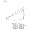
- FIG. 4 is a schematic drawing that shows the distance relationship between a CCD and an image-pickup object.
- FIG. 5 is a schematic drawing that shows the construction of another example of a fingerprint pickup apparatus of the present invention.
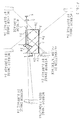
- FIG. 2 is a schematic drawing that shows the construction of a fingerprint pickup apparatus of the present invention.
- the fingerprint pickup apparatus of the present invention is provided with: a light source 1 such as a LED for radiating monochromatic red light, two kinds of first and second prisms 2 and 3, a two-dimensional CCD 4 for forming a fingerprint image and converting it into an electric signal, and a lens 5 with a low refractive index for allowing the CCD 4 to form the fingerprint image.
- a light source 1 such as a LED for radiating monochromatic red light
- first and second prisms 2 and 3 two kinds of first and second prisms 2 and 3
- a two-dimensional CCD 4 for forming a fingerprint image and converting it into an electric signal
- a lens 5 with a low refractive index for allowing the CCD 4 to form the fingerprint image.
- the first prism 2 is a trigonal prism whose bottom surface is substantially shaped into an isosceles right triangle, and has three side surfaces (shown counterclockwise starting with the first surface 2a, to the second surface 2b and the third surface 2c in the Figure).
- the width of the first surface 2a is the widest, and the widths of the second surface 2b and the third surface 2c are substantially the same.
- the second surface 2b and the third surface 2c are orthogonal to each other.
- the third surface 2c has a reflection coating thereon so as to form a mirror finished surface.
- the second prism 3 is a pentagonal prism whose bottom surface is shaped into a pentagon with the adjacent two inner angles being set at right angles, and has five side surfaces (shown counterclockwise starting with the first surface 3a, to the second surface 3b, third surface 3c, fourth surface 3d and fifth surface 3e in the Figure).
- the first surface 3a and the second surface 3b, as well as the second surface 3b and the third surface 3c, are respectively orthogonal to each other, and the first surface 3a and the third surface 3c are parallel to each other.
- the third surface 3c is wider in width than the first surface 3a.
- the fifth surface 3e, which forms an obtuse angle (135 degrees) with the first surface 3a, and the fourth surface 3d, which forms an obtuse angle with the third surface 3c, are located at positions facing the second surface 3b.
- each of the first surface 3a, the third surface 3c and the fourth surface 3d has a reflection coating thereon so as to form an entirely mirror finished surface.
- the second surface 3b has a partial reflection coating so as to form a mirror finished surface on a portion at the first surface 3a side, and the other portion at the third surface 3c side does not have a reflection coating, thereby forming a window surface.
- the refractive index of the second prism 3 is smaller than the refractive index of the first prism 2.
- the first prism 2 and the second prism 3 having the above-mentioned structures are formed into an integral part in a mode as described below.
- a portion of the first surface 2a of the first prism 2 and the entire portion of the fifth surface 3e of the second prism 3 are in contact with each other.
- the second surface 2b of the first prism 2 and the second surface 3b of the second prism 3 are in parallel with each other, and the third surface 2c of the first prism 2 is flush with the first surface 3a of the second prism 3.
- the light source 1 is disposed so as to radiate monochromatic red light with such directivity as to orthogonal to the first surface 2a of the first prism 2. Moreover, the lens 5 and the CCD 4 are arranged so that light released from the window surface of the second surface 3b of the second prism 3 is made incident thereon.
- FIG. 3 is a drawing that shows optical paths in this fingerprint pickup apparatus and mirror images derived from the first and second prisms 2 and 3.
- a finger A which is a fingerprint pickup recognition object, is put with its finger bulb (fingerprint portion) in contact with the second surface 2b of the first prism 2.
- the monochromatic red light from the light source 1 is made incident onto the first prism 2 in a manner so as to be orthogonal to the first surface 2a of the first prism 2, and totally reflected from the second surface 2b of the first prism 2 on which the finger is put.
- the incident light is not subject to total reflection so that these portions appear dark.
- the incident light is subject to total reflection so that these portions appear bright.
- an image of the fingerprint with emphasized contrast is formed.
- the reflected light of the second surface 2b is reflected by the third surface 2c of the first prism 2, and then refracted by the contact surface between the first surface 2a of the first prism 2 and the fifth surface 3e of the second prism 3, and the resulting light is allowed to enter the second prism 3.
- the light is reflected by the third surface 3c, and then successively reflected by the second surface 3b, the first surface 3a and the fourth surface 3d, and released outside from the window surface of the second surface 3b.
- the monochromatic light representative of the fingerprint image is converged onto the CCD 4 by the lens 5 so that the fingerprint image is formed on the CCD 4. Then, the CCD 4 converts the fingerprint image into an electric signal.
- the lens 5 with a low refractive index is used so as to eliminate the influence of parallax, with the result that it is necessary to lengthen the distance (optical path length) from the position of the finger A to the CCD 4. And, the lens 5 has the focal length in such a manner that an error in length due to parallax is maintained within the distance between the adjacent pixels of the CCD 4 or within half the distance thereof.
- FIG. 4 is a schematic drawing that shows the positional relationship between the CCD and the object.
- a is an actual length
- b is an observation length
- L is a horizontal distance from the CCD to the object
- X is a vertical distance from the CCD to the object.
- the allowable error range of length distortion is maintained within 0.2 % of 5.4 ⁇ m / 2.7 mm.
- the allowable error range of length distortion is maintained within 0.1% of 2.7 ⁇ m / 2.7 mm.
- the allowable error range is within 0.2 %, it is found that a correct fingerprint image is not obtained within a range of 10 mm from the origin unless the distance L is not less than 180 mm. Moreover, taking it into consideration that the allowable error range is within 0.1%, it is found that a correct fingerprint image is not obtained within a range of 10 mm from the origin unless the distance L is not less than 210 mm.
- the two prisms 2 and 3 are combined together as described above so as to reflect light a plurality of times by using the side surfaces thereof; thus, a long optical path length is achieved even with a small-size apparatus construction.
- FIG. 5 is a schematic drawing that shows the structure of another example of a fingerprint pickup apparatus of the present invention.
- those members that are the same as FIG. 2 are indicated by the same reference numerals.
- the angle formed by the third surface 3c and the fourth surface 3d of the second prism 3 is set wider as compared with the above-mentioned example, so that the reflected light of the first surface 3a is reflected by the fourth surface 3d toward the first prism 2 side.
- a portion (at the first surface 2a side) of the third surface 2c of the first prism 2 is provided as a mirror finished surface and the rest of the portion (at the second surface 2b side) is provided as a window surface, while the second surface 3b of the second prism 3 is provided as a mirror surface over its entire portion.
- the position of the light source 1 is the same as the above-mentioned example; however, the lens 5 and the CCD 4 are arranged so that light released from the window surface of the third surface 2c of the first prism 2 is made incident thereon.
- the same operations as the above-mentioned example are carried out from the radiation of the monochromatic light from the light source 1 to the reflection by the first surface 3a of the second prism 3.
- the reflected light of the first surface 3a is further reflected by the fourth surface 3d, and then refracted by the contact surface between the fifth surface 3e of the second prism 3 and the first surface 2a of the first prism 2, and the resulting light is allowed to enter the first prism 2, and then released outside from the window surface of the third surface 2c.
- the monochromatic light representative of the fingerprint image is converged onto the CCD 4 by the lens 5 so that the fingerprint image is formed on the CCD 4.
- the installation positions of the CCD 4 and the lens 5 are different from those of the above-mentioned example; thus, as compared with the above-mentioned example, it is possible to shorten the apparatus in the direction perpendicular to the second surface 2b (the second surface 3b).
- the monochromatic red light is used as the irradiation light. Therefore, it is possible to eliminate the influence of chromatic aberration that is a problem with the application of mixed color light as the light source.
- red light instead of red light, other monochromatic color lights may of course be used.
- the shapes of the two prisms 2 and 3 only give examples, and any desired shapes may be used as long as a longer optical path is provided by allowing light to be reflected by their side surfaces a plurality of times.
- a prism having a single structure may be used as long as it allows a plurality of reflections on its side surfaces.
- the lens mechanism has the focal length in such a manner that an error in length distortion due to parallax is set within a predetermined range in accordance with the pixel pitch of the CCD; therefore, it becomes possible to eliminate the influence of parallax without the need for installing any special optical members.
Landscapes
- Engineering & Computer Science (AREA)
- Physics & Mathematics (AREA)
- Optics & Photonics (AREA)
- Human Computer Interaction (AREA)
- General Physics & Mathematics (AREA)
- Multimedia (AREA)
- Theoretical Computer Science (AREA)
- Image Input (AREA)
Priority Applications (2)
| Application Number | Priority Date | Filing Date | Title |
|---|---|---|---|
| JP10262039A JP3079310B2 (ja) | 1998-09-16 | 1998-09-16 | 指紋撮像装置 |
| EP99123762A EP1104908A1 (fr) | 1998-09-16 | 1999-11-30 | Dispositif optique et dispositif et procédé d'acquisition d'empreintes digitales |
Applications Claiming Priority (2)
| Application Number | Priority Date | Filing Date | Title |
|---|---|---|---|
| JP10262039A JP3079310B2 (ja) | 1998-09-16 | 1998-09-16 | 指紋撮像装置 |
| EP99123762A EP1104908A1 (fr) | 1998-09-16 | 1999-11-30 | Dispositif optique et dispositif et procédé d'acquisition d'empreintes digitales |
Publications (1)
| Publication Number | Publication Date |
|---|---|
| EP1104908A1 true EP1104908A1 (fr) | 2001-06-06 |
Family
ID=26153179
Family Applications (1)
| Application Number | Title | Priority Date | Filing Date |
|---|---|---|---|
| EP99123762A Withdrawn EP1104908A1 (fr) | 1998-09-16 | 1999-11-30 | Dispositif optique et dispositif et procédé d'acquisition d'empreintes digitales |
Country Status (2)
| Country | Link |
|---|---|
| EP (1) | EP1104908A1 (fr) |
| JP (1) | JP3079310B2 (fr) |
Cited By (5)
| Publication number | Priority date | Publication date | Assignee | Title |
|---|---|---|---|---|
| WO2003098309A1 (fr) * | 2002-05-22 | 2003-11-27 | Carl Zeiss Jena Gmbh | Dispositif compact permettant la representation anamorphotique de la surface d'objets a l'aide d'un prisme reflechissant |
| FR2857482A1 (fr) * | 2003-07-09 | 2005-01-14 | Groupe Ecoles Telecomm | Dispositif d'imagerie optique, destine notamment a la reconnaissance d'empreintes digitales |
| RU2597465C2 (ru) * | 2015-01-23 | 2016-09-10 | Антон Сергеевич Прытков | Компактная система регистрации папиллярных узоров |
| US20170132447A1 (en) * | 2015-09-11 | 2017-05-11 | JENETRIC GmbH | Device and method for optical imaging of prints of skin parts with blood circulation |
| CN110008840A (zh) * | 2019-03-08 | 2019-07-12 | 昆山丘钛微电子科技有限公司 | 光学指纹模组及指纹识别显示装置 |
Citations (7)
| Publication number | Priority date | Publication date | Assignee | Title |
|---|---|---|---|---|
| WO1993011631A1 (fr) * | 1991-12-06 | 1993-06-10 | Vlsi Vision Limited | Agencement de detecteurs a semi-conducteurs |
| EP0616295A2 (fr) * | 1993-02-16 | 1994-09-21 | HAHN BIOMETRIX GmbH i. G. | Procédé et arrangement de vérification des empreintes digitales |
| WO1996017480A2 (fr) * | 1994-11-30 | 1996-06-06 | Digital Biometrics, Inc. | Releve de l'empreinte de la paume |
| DE19509751A1 (de) * | 1995-03-17 | 1996-09-19 | Hans J Dr Einighammer | Optisches Abbildungssystem zur Darstellung von Papillarleisten mit Hilfe interner Reflexion an brechender teilreflektierender Grenzfläche |
| US5625448A (en) * | 1995-03-16 | 1997-04-29 | Printrak International, Inc. | Fingerprint imaging |
| JPH1131216A (ja) * | 1997-07-14 | 1999-02-02 | Olympus Optical Co Ltd | 指紋読取光学系 |
| DE19816428A1 (de) * | 1997-09-01 | 1999-03-04 | Fujitsu Ltd | Erfassungsvorrichtung für Daten einer unebenen Oberfläche |
-
1998
- 1998-09-16 JP JP10262039A patent/JP3079310B2/ja not_active Expired - Fee Related
-
1999
- 1999-11-30 EP EP99123762A patent/EP1104908A1/fr not_active Withdrawn
Patent Citations (7)
| Publication number | Priority date | Publication date | Assignee | Title |
|---|---|---|---|---|
| WO1993011631A1 (fr) * | 1991-12-06 | 1993-06-10 | Vlsi Vision Limited | Agencement de detecteurs a semi-conducteurs |
| EP0616295A2 (fr) * | 1993-02-16 | 1994-09-21 | HAHN BIOMETRIX GmbH i. G. | Procédé et arrangement de vérification des empreintes digitales |
| WO1996017480A2 (fr) * | 1994-11-30 | 1996-06-06 | Digital Biometrics, Inc. | Releve de l'empreinte de la paume |
| US5625448A (en) * | 1995-03-16 | 1997-04-29 | Printrak International, Inc. | Fingerprint imaging |
| DE19509751A1 (de) * | 1995-03-17 | 1996-09-19 | Hans J Dr Einighammer | Optisches Abbildungssystem zur Darstellung von Papillarleisten mit Hilfe interner Reflexion an brechender teilreflektierender Grenzfläche |
| JPH1131216A (ja) * | 1997-07-14 | 1999-02-02 | Olympus Optical Co Ltd | 指紋読取光学系 |
| DE19816428A1 (de) * | 1997-09-01 | 1999-03-04 | Fujitsu Ltd | Erfassungsvorrichtung für Daten einer unebenen Oberfläche |
Non-Patent Citations (1)
| Title |
|---|
| PATENT ABSTRACTS OF JAPAN vol. 1999, no. 05 31 May 1999 (1999-05-31) * |
Cited By (9)
| Publication number | Priority date | Publication date | Assignee | Title |
|---|---|---|---|---|
| WO2003098309A1 (fr) * | 2002-05-22 | 2003-11-27 | Carl Zeiss Jena Gmbh | Dispositif compact permettant la representation anamorphotique de la surface d'objets a l'aide d'un prisme reflechissant |
| FR2857482A1 (fr) * | 2003-07-09 | 2005-01-14 | Groupe Ecoles Telecomm | Dispositif d'imagerie optique, destine notamment a la reconnaissance d'empreintes digitales |
| WO2005006241A3 (fr) * | 2003-07-09 | 2005-05-19 | Groupe Ecoles Telecomm | Dispositif d'imagerie optique, destine notamment a la reconnaissance d'empreintes digitales. |
| US7798405B2 (en) | 2003-07-09 | 2010-09-21 | New Imaging Technologies | Optical imaging device for the recognition of finger prints |
| RU2597465C2 (ru) * | 2015-01-23 | 2016-09-10 | Антон Сергеевич Прытков | Компактная система регистрации папиллярных узоров |
| US20170132447A1 (en) * | 2015-09-11 | 2017-05-11 | JENETRIC GmbH | Device and method for optical imaging of prints of skin parts with blood circulation |
| US10296775B2 (en) * | 2015-09-11 | 2019-05-21 | JENETRIC GmbH | Device and method for optical imaging of prints of skin parts with blood circulation |
| CN110008840A (zh) * | 2019-03-08 | 2019-07-12 | 昆山丘钛微电子科技有限公司 | 光学指纹模组及指纹识别显示装置 |
| CN110008840B (zh) * | 2019-03-08 | 2022-02-01 | 昆山丘钛生物识别科技有限公司 | 光学指纹模组及指纹识别显示装置 |
Also Published As
| Publication number | Publication date |
|---|---|
| JP3079310B2 (ja) | 2000-08-21 |
| JP2000090250A (ja) | 2000-03-31 |
Similar Documents
| Publication | Publication Date | Title |
|---|---|---|
| US5187748A (en) | Optical apparatus for fingerprint identification system | |
| US6657185B2 (en) | Pattern detector for capturing images with reduced distortion | |
| US9400913B2 (en) | Optical fingerprint recognition apparatus | |
| US6324020B1 (en) | Method and apparatus for reduction of trapezoidal distortion and improvement of image sharpness in an optical image capturing system | |
| US5526436A (en) | Image detecting apparatus for an individual identifying system | |
| JPH10289304A (ja) | 指紋画像入力装置 | |
| JPH1183459A (ja) | 凹凸面情報検出装置 | |
| US20030103769A1 (en) | Sensor device | |
| JP2000090248A (ja) | 指紋画像撮像装置及びそれを用いた指紋照合装置 | |
| US6912300B1 (en) | Irregular pattern reader | |
| CN105550668A (zh) | 一种活体生物特征采集装置及识别活体生物特征的方法 | |
| KR100349832B1 (ko) | 라인스캔형 지문입력장치 | |
| JP3079310B2 (ja) | 指紋撮像装置 | |
| JP2000090247A (ja) | 指紋画像撮像装置及びそれを用いた指紋照合装置 | |
| KR100726100B1 (ko) | 지문인식장치용 광학시스템 | |
| JP2005228191A (ja) | 指紋画像入力装置 | |
| JPS62266686A (ja) | 指紋照合装置 | |
| CN215010481U (zh) | 成像系统、图像传感器、感光像素及电子设备 | |
| KR20040042727A (ko) | 광학 지문입력장치 | |
| JPS5943869B2 (ja) | センサ装置のための原稿の照明及び結像のための機構 | |
| CN113452936A (zh) | 成像系统、图像传感器、感光像素及电子设备 | |
| KR20080076353A (ko) | 차량번호 인식용 카메라 | |
| JPH1115948A (ja) | 指紋入力装置 | |
| CN111131680A (zh) | 生物识别摄像模块 | |
| US20030021450A1 (en) | Fingerprint imaging device |
Legal Events
| Date | Code | Title | Description |
|---|---|---|---|
| PUAI | Public reference made under article 153(3) epc to a published international application that has entered the european phase |
Free format text: ORIGINAL CODE: 0009012 |
|
| AK | Designated contracting states |
Kind code of ref document: A1 Designated state(s): DE FR GB |
|
| AX | Request for extension of the european patent |
Free format text: AL;LT;LV;MK;RO;SI |
|
| 17P | Request for examination filed |
Effective date: 20010622 |
|
| 17Q | First examination report despatched |
Effective date: 20010726 |
|
| AKX | Designation fees paid |
Free format text: DE FR GB |
|
| STAA | Information on the status of an ep patent application or granted ep patent |
Free format text: STATUS: THE APPLICATION IS DEEMED TO BE WITHDRAWN |
|
| 18D | Application deemed to be withdrawn |
Effective date: 20011206 |