EP1104912A2 - CNN bionisches Auge oder andere topographische sensorische Organe oder Kombination - Google Patents
CNN bionisches Auge oder andere topographische sensorische Organe oder Kombination Download PDFInfo
- Publication number
- EP1104912A2 EP1104912A2 EP01200397A EP01200397A EP1104912A2 EP 1104912 A2 EP1104912 A2 EP 1104912A2 EP 01200397 A EP01200397 A EP 01200397A EP 01200397 A EP01200397 A EP 01200397A EP 1104912 A2 EP1104912 A2 EP 1104912A2
- Authority
- EP
- European Patent Office
- Prior art keywords
- cnn
- cells
- topographic
- sensory
- stimuli
- Prior art date
- Legal status (The legal status is an assumption and is not a legal conclusion. Google has not performed a legal analysis and makes no representation as to the accuracy of the status listed.)
- Withdrawn
Links
Images



Classifications
-
- G—PHYSICS
- G06—COMPUTING OR CALCULATING; COUNTING
- G06N—COMPUTING ARRANGEMENTS BASED ON SPECIFIC COMPUTATIONAL MODELS
- G06N3/00—Computing arrangements based on biological models
- G06N3/02—Neural networks
- G06N3/06—Physical realisation, i.e. hardware implementation of neural networks, neurons or parts of neurons
- G06N3/063—Physical realisation, i.e. hardware implementation of neural networks, neurons or parts of neurons using electronic means
-
- G—PHYSICS
- G06—COMPUTING OR CALCULATING; COUNTING
- G06N—COMPUTING ARRANGEMENTS BASED ON SPECIFIC COMPUTATIONAL MODELS
- G06N3/00—Computing arrangements based on biological models
- G06N3/02—Neural networks
- G06N3/04—Architecture, e.g. interconnection topology
- G06N3/042—Knowledge-based neural networks; Logical representations of neural networks
-
- G—PHYSICS
- G06—COMPUTING OR CALCULATING; COUNTING
- G06N—COMPUTING ARRANGEMENTS BASED ON SPECIFIC COMPUTATIONAL MODELS
- G06N3/00—Computing arrangements based on biological models
- G06N3/02—Neural networks
- G06N3/04—Architecture, e.g. interconnection topology
- G06N3/045—Combinations of networks
-
- G—PHYSICS
- G06—COMPUTING OR CALCULATING; COUNTING
- G06N—COMPUTING ARRANGEMENTS BASED ON SPECIFIC COMPUTATIONAL MODELS
- G06N3/00—Computing arrangements based on biological models
- G06N3/02—Neural networks
- G06N3/04—Architecture, e.g. interconnection topology
- G06N3/0464—Convolutional networks [CNN, ConvNet]
Definitions
- the present invention relates to cellular neural networks (CNN), and more particularly to a fully programmable, or programmed, CNN supercomputer that functions as a CNN bionic eye or other topographic sensory organ, or combinations of such organs which may have functions that are extensions of those that occur naturally in living organisms.
- CNN cellular neural networks
- a cellular neural network is a multi-dimensional lattice array of a plurality of identical cells.
- the array may be either square, rectangular, or hexagonal.
- the array in any direction can have one or more cells, i.e., there does not have to be the same number of cells in each of the n-dimensions of the array.
- the cells closet to it are its neighbor cells.
- the neighbor cells of each cell expand concentrically from that single cell as concentric circles, or partial concentric circles, of neighbor cells.
- Each cell in the array interacts non-linearly and in continuous time with a prescribed number of concentric circles of neighbor cells within the lattice. Adjacent cells can interact directly with each other, and cells not directly connected together may affect each other indirectly because of the propagation effects of the CNN.
- each circle of neighbor cells will also be two dimensional and be a sub-set of the cells in the single-layer of the CNN.
- the neighbor cells In a three dimensional CNN, there will be at least two layers of CNNs and the neighbor cells may be either restricted to the single layer in which they are physically located, or the neighborhood of cells could also be three dimensional and incorporate portions of several layers much like layers of an onion. The actual application dictates whether the neighborhood of cells are two or three dimensional.
- Each cell contains linear and nonlinear circuit elements, which may include linear capacitors, linear inductors, linear resistors, linear and nonlinear controlled sources, and independent sources.
- the CNN universal machine and supercomputer extends the basic CNN into a cellular analog stored-program multidimensional array computer with local analog and logic memory, analogical computing units, and local and global communication and control units.
- the global analog stored-program memory concept is a key element of the CNN universal chip architecture providing the implementation of analogical algorithms using time-multiplex templates.
- the CNN machine is universal in the same sense as a Turing machine except that all of the signals are analog, not digital.
- the so called dual computing structure in the CNN architecture allows a direct combination of analog and logic signals, without any analog-digital conversion.
- the CNN universal machine was invented with this device allowing one to program an unlimited range of spatio-temporal transformations, linear and nonlinear, in 2 or 3 dimensions.
- CNN templates have also been used to successfully process pictures with areas of vastly different local illumination.
- the CNN universal machine and supercomputer can be used to implement any topographic bionic sensor, and to illustrate that, this disclosure presents the details of how to implement the CNN universal machine to build a bionic eye that can perform all the known functions of vertebrate retinas, and extend beyond the phenomenological models. The same techniques are also applicable to the implementation of other bionic sensors using the CNN.
- the image processing functions performed by the CNN universal machine encompass, but are not limited to, those performed by many different vertebrate retinas ranging from salamanders to primates. All the functional properties of these retinas, as well as others that do not exist in nature, and other sensory organs can be implemented in the same CNN universal machine. These retinas, and other sensory organs, not only respond in specific ways to the sensory input, but they adjust their responsive properties to match the environment and the objective of the animal. All of these functions and the adjustments in function performed by biological sensors are also implementable in a CNN universal machine through its analogic (analog and logical) programming capability.
- the functional properties of the CNN universal machine are not built in (not hard wired) but can be programmed, and the programming can be self adapting, like the biological sensors themselves, such as a retina, to match the content and context of the visual and other sensory task.
- the CNN universal machine can perform both sensory processing and adaptive functions that go far beyond vertebrate sensors, both in their complexity, range of adaptability and speed of operation.
- the retina processes information sequentially across 5 sheets, or layers, of neurons
- the CNN bionic eye can process information across a very large number of such layers in the same time period that a biological retina processes the same information, at least 10,000 such "slices" or processes within that time period.
- the biological retina adapts to a few important contexts of the visual scene, including brightness, texture and movement.
- the CNN universal machine bionic eye is capable of adapting to those and many more possible contexts, including those never even seen by biological retinas.
- the biological retina processes the visual scene in about 100 msec.
- the CNN bionic eye can perform these functions in less than one millionth of a second. Similar arguments are valid to othertopographic sensory organs (tactile, somatosensory, olfactory, etc.).
- the applications for the CNN bionic eye, or other CNN bionic sensors, are limitless.
- the CNN bionic eye is an image processing supercomputer, no larger than a thumbnail, and consuming minimal power. It is capable of processing a visual image in one millionth of a second, then store that image, be reprogrammed in a microsecond, and then process the stored image with no limit to the number of cycles that can be performed.
- the logical component in the global analogic program unit (GAPU) of the CNN universal machine allows the device to adapt to the context, as well as the content, of the visual scene.
- GPU global analogic program unit
- a key point of the implementation is that all the sensors are placed on, or in close proximity to, the chip. In addition to the photosensors, pressure, temperature, and chemical microsensors could also be placed on the chip, as well as others.
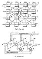
- Figure 1 is a two-dimensional simplified block schematic diagram of a single-layer cellular neural network of the prior art showing a CNN having the interconnections between cells being only to the nearest neighbors.
- Figure 2 is a block schematic representation of the interconnection between the layers of a multi-layer CNN of the prior art.
- Figure 3a is a graphical illustration of a layer of a universal CNN machine of the prior art.
- Figure 3b is an expanded block diagram of a single cell of the prior art CNN machine of Figure 3a.
- Figure 3c is an expanded block diagram of the GAPU of the prior art CNN of Figure 3a.
- Figures 4a and 4b together present a schematic representation of an equivalent circuit of a single enhanced prior art CNN cell as in Figure 3b.
- FIG. 5 is an expanded block diagram representation of GAPU of Figure 3c.
- Figure 6 is a simplified schematic representation of a representative eye and the layers of the retina.
- Figure 7a is a functional schematic representation of the layers of the retina of a representative eye and the processing of information by the various layers.
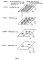
- Figure 7b is a simplified functional schematic representation of the layers of the CNN universal machine programmed to simulate the processing of information by the various layers of the retina as shown in Figure 7a.
- Figure 7c is a simplified functional block diagram of the operation of the CNN universal machine of Figure 7b for simulation of the processing of information by the various layers of the retina of Figure 7a.
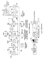
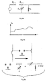
- Figure 8a is a schematic representation of the inclusion of a variable capacitance within each CNN cell.
- Figure 8b is a graphical representation of the capacitance value with respect to time of a programmably variable capacitor.
- Figure 8c is a schematic representation of the inclusion of a time-delay circuit, such as a variable capacitance in an R-C circuit, in the signal transmission path between two CNN layers.
- a time-delay circuit such as a variable capacitance in an R-C circuit
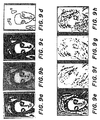
- Figures 9a-9h are an original gray scale image is mapped into several other images by a CNN universal machine from the original gray scale image of Figure 9a using different analogic programming templates.
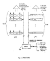
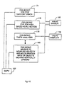
- Figure 10 is a diagrammatical representation of an analogic algorithm for combining various modalities in the same CNN universal machine.
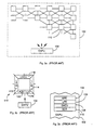
- Figure 11a is a schematic representation of single point measurement of a response of a CNN layer.
- Figure 11b is a schematic representation of multiple point measurement of a response of a CNN layer.
- FIG. 6 there is shown a simplified schematic representation of a representative eye and the layers of the retina.
- the back wall, or sclera 134 of the eye
- the lens 132 on the front of the eye.
- the retina of the eye which is physically located near the sclera 134, is made-up of a series of layers which face away from lens 132.
- the incoming light 130 enters the eye through lens 132, passes completely through the retina, and then is in essence reflected off the sclera 134 before it is processed by the retina layers.
- each layer processes the light information serially starting with the layer of photorecptors 136 which is made-up of the rods and cones.
- This first layer is the only layer that actually interacts directly with the incoming light.
- Each of the remaining layers receives neurological impulses from the preceding layer, or layers, and it is those neurological impulses from the preceding layer that each subsequent layer operates on.
- the deeper the layer of interest the fewer cells that that layer contains, thus it is said that the "grain" of each layer increases the deeper the layer is.
- each cell in each subsequent layer of the retina receives its input signal from numerous cells (perhaps from 2 or 3 to 100, or more) in the previous layer of the retina.
- the layers in order are the horizontal cells 138, the bipolar cells 140, the amacrine cells 142 and the ganglion cells 144, with each of these layers performing a different function and modifying the neurological signal 146 from the previous layer to form the output signal 148 that is presented to the brain for further processing.
- the light and light information passes through the retina three times as signals 130, 146 and 148.
- Figure 7a Physiological recordings from intact retinas and retinal slices have yielded the functional parameters that underlie retinal function. These functional parameters are summarized in Figure 7a as 17 arrows, each representing a functional parameter of the eye. Figure 7a also identifies the five layers illustrated in Figure 6, and thus, Figure 7a schematically illustrates the function performed by each layer of the retina and its immediate interaction with another layer or layers.
- the 17 functions performed by the various layers of the eye are summarized below.
- the photoreceptors (136) transduce light and they become active neurally.
- the horizontal cells 138 average the activity at each point from input signals received from many-many rods and cones in the photoreceptor layer 136. Since each cell in layer 138 receives an input from many cells in layer 136, that averaged image from layer 136 per cell in layer 138 is going to be very blurred because many points converge on each one. If the original image is dynamic, the result here is also blurred in time by the averaging action.
- the difference is then taken between the signals from the first and second functions.
- the difference since the difference is being taken between a blurred image and a sharp image, the result is going to identify the edges of the original image of the incoming light 130.
- This difference taking thus, enhances the edges and begins to bring out some of the details of the incoming image being received by lens 130.
- the difference signal is emphasized which in essence turns up the gain at the edges of the original image.
- bipolar cells 140 there are two kinds of cells: one type looks at increases in lightness; and the other type looks at increases in darkness. Thinking of a boundary between light and dark, those two events are always going to be neighboring each other with the actual edge being the zero-crossing between them and not otherwise defined. This can be thought of as the second spacial derivative of the original image.
- the retina has substantially been emphasizing spacial differences in the original image.
- the retina changes in time have been identified.
- the only portion of the original image that produces a resulting signal here is that portion of the original image that is moving.
- the ganglion layer 144 gathers this activity with the final output consisting of the changes in time that have been identified the instant that they occur with the signal then being shut-off.
- FIG. 1 there is shown a 4x4 two-dimensional cellular neural network of the prior art by way of illustration.
- the cells C(i,j) are shown here in a square array of four rows and four columns with "i" representing the row number and "j" representing the column number.
- cell 12 ⁇ C(2,2) ⁇ is shown interconnected with cells 30-44 by links 14-28, respectively.
- Each of links 14-28 shown here are bidirectional between the two cells to which that link is connected.
- FIG. 2 there is shown a typical schematic representation of a multi-layer CNN of the prior art having layers 60-64.
- the input signal is shown being applied directly to layer 60 and feed forward path 68, and via delays 74 and 76 to layers 62 and 64, respectively.
- the output signal from layer 60 is applied to layer 62 via delay 70
- the output signal from layer 62 is applied to layer 64 via delay 72.
- the value of delay, 6, for each of delays 70-76 is substantially equal.
- the CNN universal machine of the present invention provides at least three new capabilities; the analog stored program and the time-multiplex operation of layers, the wireless detection, and flexible representation of various PDEs using a chaos circuit.
- the CNN can be defined as an analog cellular nonlinear dynamic processor array characterized by the following features:
- the original CNN array 10 (see Figure 1), with some elementary logic additions, is used as a nucleus for the CNN Supercomputer with the following additional features and circuit elements being responsible for the universal capabilities of the CNN Supercomputer.
- Analog two or three dimensional array-signals which assume continuous values in continuous or discrete-time over an interval are used.
- FIG. 3a there is shown a partial block diagram of the CNN universal chip 100. This chip architecture is divided into two distinct regions as shown in Figure 3a. In the upper portion of Figure 3a there is what appears to be the CNN structure shown in Figure 1, and in the lower portion there is a block representation of the global analogical programming unit (GAPU) 102 which is discussed further below.
- GPU global analogical programming unit
- the grid of individual cells 110 as shown in Figure 3a as being rectangular could be any two-dimensional configuration (triangular, hexagonal, polygonal, etc.). This is more application dependent than theory dependent. Additionally, different grid sizes and shapes can be used for different layers in a multi-layer CNN.
- the universal chip architecture illustrated in Figure 3a represents the functional architecture of the CNN universal machine in two senses: (1) several CNN universal chips 100 (e.g. layers 60-64 in Figure 2) stacked upon each other results in a three dimensional universal CNN machine, and (2) several two-dimensional "layers" (as in Figure 1) of a three-dimensional CNN machine can be implemented on the CNN universal chip architecture with time multiplexing using local analog and logic memory registers.
- several chips can be placed next to each other on a planar substrate with only the border cells on one chip connected to border cells on an adjacent chip as if all of the cells had been on the same larger chip. If the feedback/feedforward signals of the CNN are to be connected to more than just the nearest circle of neighbor cells then the border cells of each of the adjacent cells would also have to be connected to the appropriate additional cells on each chip as if those cells were each on the same chip.
- FIG. 3b An expanded view of any and every CNN cell 110 of Figure 3a is shown in more detail in Figure 3b.
- additional analog and logical circuit elements associated with each cell. It should be noted here that "logical” and “digital” are not to be equated with each other.
- a digital circuit includes various gates and registers, whereas a logical circuit is an analog circuit that processes logical values without doing so with conventional digital building blocks.
- the additional circuit elements in each cell of the CNN universal machine are a local analog memory unit (LAM) 112, a local logic memory register (LLM) 114, a local logic unit (LLU) 116, a local communications and control unit (LCCU) 118, and a local analog output unit (LAOU) 120.
- LAM local analog memory unit
- LLM local logic memory register
- LLU local logic unit
- LCCU local communications and control unit
- LAOU local analog output unit
- the global analogical programming unit (GAPU) 102 controls the entire cell and is shown in more detail in Figure 3c.
- GAPU 102 has three constituent parts, an analog program register (APR) 104, a logical program register (LPR) 106, and a global analogical control unit (GACU) 108.
- APR analog program register
- LPR logical program register
- GACU global analogical control unit
- GAPUs 102 can be used in an array partitioning GAPU 102 between the chips working together with a central GAPU 102.
- APR 104 can also be divided to form an analog cache register.
- Figures 4a and 4b together present a schematic diagram of an equivalent circuit representation of a typical individual cell 110 (see Figure 3b).
- the suffixes u, x and y denote the input, state and output, respectively, of the cell.
- node voltage v xij is called the state of the cell
- node voltage v uij is called the input of the cell
- the node voltage v yij is called the output of the analog portion of the cell
- Y ij is the logical output of the cell.
- Templates A and B define the feedback and feedforward, respectively, between neighbor cells and are programmable via GAPU 102. They each contain variable gain amplifiers with the gain values being received externally.
- V uij various values of node voltage
- the input signals are stored as analog signals locally in LAM1 112 1 .
- the initial state, v xij (0) is also stored locally as an analog signal in LAM2 112 2
- subsequent state values are store sequentially as analog signals in LAM3 112 3 .
- several consecutive output values, v yij are stored as analog signals in LAM4 112 4 .
- LAM4 112 4 Once at least one result is present in LAM4 112 4 , it can be used as an input or initial state to LAOU 120, meanwhile different B and A templates can be programmed to calculate iterative instructions. In very high speed applications LAM4 112 4 could be an analog delay line. Now, after several consecutive results have been sorted in LAM4 112 4 , they are combined by LAOU 120 to calculate an output value, v* yij .
- LAOU 120 could be a diode or a small amplifier which adds the analog values from LAM4 112 4 .
- One implementation of LAMs 112 could be capacitors on which the analog voltage can be stored.
- LAM4 112 4 In the local analog memory (LAM) 112 x , in addition to the local input, state, and output memory elements, some additional output memory cells are used in LAM4 112 4 . These additional output memory cells provide for the application of a local analog output unit (LAOU 120) where the analog memory values are combined by simple analog circuits (using programmable switches one particular operator can be selected). These elements can also be used (in an analogical algorithm) for the implementation of branching into several parallel branches (time multiplexing with analog signal values).
- the signal v* yij is applied to a simple bipolar/unipolar shift unit 122 transforms the analog output to logic values with consecutive values being stored in a local logic memory register (LLM) 114 which may be implemented, for example, by a multi-stage analog shift register where the converted logic signals are stored in analog form (just yes or no). Having several consecutive logic values stored in LLM 114 allows for the implementations of branching in the analogical algorithms (at logic signal arrays).
- LLM local logic memory register
- LLU 116 is programmable to combine the logic values stored in LLM 114 into a single output. Further, LLU 116 is programmable from GAPU 102 and may be implemented, for example, e.g., as a memory or a PLA.
- the logical output signal, Y ij provides a "yes" or "no" response to whether the feature that the CNN was programmed to detect by templates A and B was observed. For example, vertical edges and corners and where they occurred might be detected.
- the analog-logical (analogical) processing is serial with the analog processing performed first followed by the logical processing.
- LCCU 118 controls the timing of the various steps in the processing by means of a series of switches that are controlled by GAPU 102. These switches interface with the various elements of Figure 4a via the broken line segments shown in that figure thus controlling the operation of LAMs 112.
- the switches of LCCU 118 can be implemented several ways including, for example, MOS transistors or SCRs, with the switches being locally the same in each cell.
- the CNN supercomputer employees multiplexing and the results are locally stored in each layer, the results from several layers that have been processed simultaneously can be combined with no communication cost since everything is locally stored. This is key. Also analog signals are used so that there is no need for A-D conversions in each cell; the actual signals are stored.
- the local connectivity here provides a high speed supercomputer that is very small and uses very little power.
- FIG. 5 is a block diagram representation of GAPU 102 which as stated in relation to Figure 3c has three parts:
- the division of the on-chip and off-chip analog program storage can be arranged to introduce analog-cache storage (ACS) as well to supplement the on-chip APR 104 storage.
- ACS analog-cache storage
- the analogical CNN algorithms can be described by an analogical CNN language (or an equivalent block diagram). This language is translated by a computer to the analogical CNN machine code.
- each of the APR 104 registers of Figure 5 represent different analog instructions. These instructions consist of all of the possible values for each of the A and B templates, as well as the bias current, I.
- the bias current can also be thought of as a threshold.
- Each contains an instruction to program the individual templates: "A” with 9 numbers (3x3 matrix with values for feedback to the connected cells of the CNN), "B” with 9 numbers (3x3 matrix with values for feedforward to the connected cells of the CNN), and "I” with 1 number for the bias current of the single cell itself.
- each register in LPR 106 is dependent upon the number of logic values to be combined and the number of different logic instructions.
- the selection of the appropriate analog templates, i.e. analog instructions, and the logical instructions is made by GACU 108.
- the next instruction is a corner detecting template.
- GAPU 108 then loads to the local programming values of the "A", "B" and "I" templates.
- the contour is organized in the sequence of the data and instructions.
- GAPU 108 is a sequential logical store of which instructions to select and in what order from APR 104 and LPR 106 to detect the desired pattern, etc.
- the time and space constants, as well as the transfer functions, and modes of adaptive behavior for retinal image processing must be identified from the data gather through years of biological research that is already available in the published literature and are summarized in the 17 parameters displayed diagrammatically in Figure 7a.
- the CNN templates, etc. can be derived and then programmed into the CNN universal machine in the following ways. The key is how to translate them into the CNN universal chip.
- the CNN literature contains several papers on the "learning" aspects of CNN to relatively automatically generate the necessary "A" and "B" templates to perform desired functions. Additionally, also in the literature, some of the published biological models contain matrices to explain various operations of sensory organs which can be used will little variation to program certain functions in the CNN universal machine.
- the CNN universal machine is powerful and flexible enough to be used to match the function of all known vertebrate retinas, and can easily perform other functions that go far beyond biological possibilities.
- the basic functions of contrast detection, color coding, movement detection, directional selectivity can be easily performed by the CNN universal machine on a single chip just by programming using analogic software. Most important, these functional properties can be modified according to the brightness, texture, contrast and rate of movement in the visual scene, and this modification can take place either locally or globally. In this way the CNN universal machine can be programmed to operate at the most efficient level as determined by both the instantaneous visual scene and the long range visual goal.
- the CNN bionic eye is programmed using the known physiological parameters and models of retinal function. Physiological recordings from intact retinas and retinal slices have yielded the functional parameters that underlie retinal function.
- Figure 7a shows a schematic diagram of the retina, along with 17 arrows, each representing a functional parameter. This structure forms the basis of the implementation of a CNN bionic eye.
- the vertical arrows represent time constants, the horizontal arrows represent spacial constants, and the curved arrows represent transfer functions.
- This set of parameters specifies overall retinal function which has been illustrated in the literature by implementation on a digital image processor.
- the CNN bionic eye can also adjust to both intrinsic and extrinsic properties of the visual scene. By basing the programming of the CNN bionic eye on physiological parameters, the bionic eye will be endowed with the instantaneous performance characteristics that follow biological retinal function. These characteristics are further subject to modulation as a function of extrinsic properties via the global analogic program unit (GAPU 102 in Figure 3a), similar to the way biological retinas modulate performance characteristics.
- GPU 102 in Figure 3a the global analogic program unit
- Figure 9a shows an original gray scale image that was processed by the CNN universal machine with different "A”, "B” and "I” templates as shown in Table I to generate Figures 9b-h. Briefly:
- the CNN layer and interconnection architecture is started by a multilayer CNN with as many layers as physiological ones.
- the template structure is derived to mimic directly the receptive field organizations of the retina.
- all layers which are involved should be considered together.
- Feedforward layers are considered sequentially, by time multiplexing the consecutive layers in a programmable way. If more than one layer is connected by feedback, complex CNN cells are used in the physical CNN implementation.
- the CNN universal machine has the computational power to perform highly complex processing of visual images with great speed, consuming little power, while only occupying the space of a computer chip.
- the programming of the operation of a CNN has great flexibility. It can be externally programmed to perform an enormous variety of image processing functions, feed the results of its processing back to itself so that it can reprogram itself to adapt to different qualities of the image or scene, and its operation can be reset as a function of the requirements of its host.
- Biological retinas act primarily to abstract information about the dynamics of the visual scene. Movement, direction of movement, onset and termination of local and global events, expanding and contracting images associated with, for example, approaching targets, are all common elements of visual function.
- a time delay is sometimes necessary between various functions, or steps in the process.
- a controllable capacitor in an R-C circuit or an FET can be included on the CNN bionic eye chip to provide the ability to provide a programmed variable time delay.
- the time delay can be programmed into the operational routine and stored in the local analog memory of the affected CNN cells (LAM 112 of Figure 3b).
- LAM 112 of Figure 3b the local analog memory of the affected CNN cells
- Identical controllable capacitors, C x can be placed on the CNN chip to control the speed of the basic dynamics (the time constant) of the CNN array.
- Figure 8a illustrates the placement of the capacitor, C x , in the front end of the individual CNN circuit of Figure 4a.
- the capacitors, C x may vary in a preprogrammed way (part of an analogic program of the CNN) or continuously depending upon the local output voltages of CNN cells on different layers (see Figure 8b).
- Controllable capacitors can also be used to change the time delay of a template element.
- Figure 8c shows a circuit implementation in the transmission path between CNN layers with a variable capacitor or delay-line inserted in that path. Hence, different delay values between the CNN layers and in the different positions of either "A" or "B" template can be implemented. Delay templates can also be useful in many motion-related applications.
- the time constant can easily be implemented on an IC (CNN universal machine). This provides the option of placing a variable capacitor, or other time delay mechanism, on the Si chip itself and simply varying the delay time by programmably varying a control voltage level.
- the local analog memory cells can be used to store a signal value that is applied to the appropriate CNN layer by the analogic program at the appropriate time.
- a second "A" or “B” template circuit (bank of OTAs --Operational Transconductance Amplifiers) can be implemented, switching them in under the control of programmable switches, as part of the switch configuration of the CNN universal chip. If more than one layer is to be effected in the same way or at the same time, then those CNN cells can be placed on a single physical layer as complex CNN cells.
- the key to making the CNN perform like a biological retina is to create a correspondence between the CNN templates and measured interactions in living retinas. Rather than defining the properties of individual cells, information about retinal networks has been extracted from the literature. Spatial interactions are defined in terms of a "space constant” that describes the lateral spread or diffusion of activity. This diffusion is then incorporated into the design of the cloning template of the CNN. Similar procedures are followed for implementing time constants and transfer functions for the bionic eye. The 17 parameters that constitute the design properties of the retina are illustrated in Figure 7a above.
- Figure 7b is a simplified functional schematic representation of the layers of the CNN universal machine programmed to simulate the processing of information by the various layers of the retina as shown in Figure 7a.
- Layers 2-5 (138-144) of Figure 7a are illustrated as individual CNN Layers 150-156 and identified on the left with the same terminology used in Figure 7a.
- Layer 1 (136) of Figure 7a is illustrated here as the photoreceptors that gather the image and apply it to the layer of horizontal cells 138 in the retina, represented here as CNN cells 150 in Layer 2.
- Figure 7c shows the corresponding functional block diagram of the operation of the simplified CNN universal machine of Figure 7b with each of blocks 160-166 programmed to function according to the parameters related to the corresponding layer of the retina of Figure 7a.
- Single point measurements in all physiological layers can be used as responses to the on-center and off-center light stimuli.
- a secondary algorithm can be derived to adjust the different template elements for on-center and corresponding off-center images. Normally, these adjustments are performed in a heuristic way, taking into account the physiological information as well as excitation-inhibition, etc.
- the different template element dynamics or aggregated interactions between neighboring cells using a larger light spot can be measured or determined from the literature on the retina, or other sensory organs.
- CNN template design methods can also be used.
- the input-output patterns from these experiments can be fed to known template learning algorithms, e.g. a genetic template learning algorithm. In this way the receptive field organization of retina or another sensory organ can be "reverse engineered”.
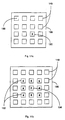
- Figures 11a and 11b illustrate these single point multiple point measurements on a CNN layer 186 containing an array of individual CNN cells 148.
- Biological retinas consist of sheets, or layers, of neurons, arranged in very large arrays existing of between 1 million or 100,000 neurons. The number of element decreases dramatically as one moves from the outer to the inner layers of the retina. Therefore the grain of the retina changes, dynamically. In order to account for the changes in grain, a mechanism for programming layer compression or expansion, whereby the number of elements and the distance between these elements can be modified in the program, must be included in the CNN bionic eye.
- the functions of layer compression and expansion can be performed for grain of layers by using a physical CNN grid with the number of cells corresponding to the finest grain (the most CNN or retinal cells), with some of the rows and columns of the CNN chip programmed to switch off to simulate other layers of the retina with a coarser grain.
- the function of a single biological layer can be broken into sub-steps and modeled with more CNN layers (e.g., for the outer plexiform layer of the retina, 2 CNN layers can be used, one to model the interactions between the photoreceptors and the second for the horizontal cells) or the function of several biological layers can be lumped into a single CNN layer (e.g., the function of the photoreceptors, the outer plexiform layer, and the inner plexiform layers).
- CNN layers e.g., for the outer plexiform layer of the retina, 2 CNN layers can be used, one to model the interactions between the photoreceptors and the second for the horizontal cells
- the function of several biological layers can be lumped into a single CNN layer (e.g., the function of the photoreceptors, the outer plexiform layer, and the inner plexiform layers).
- the compression of the function of retinal layers is done in the CNN universal machine by deleting the time multiplexing in the multi-layer CNN analogic algorithm.
- Another technique is to use complex cells (i.e. 2-3 layers physically compressed by grouping the cells in identical positions on different layers into a single complex cell, which is then placed on a single physical layer on silicon).
- Biological retina function is not fixed, but can vary as the visual scene or the goals of the host are changed. For example, the "gain" of the retina is decreased when brightness of the visual scene increases. Gain is also decreased in local regions when the texture or contrast in those regions increases. These gain changes keep the retinal output within an acceptably narrow range of magnitudes, regardless of input conditions. Similarly, it is thought that biological retinal function can vary according to conditions of stress or excitement.
- output from the eye itself can be directed to the GAPU (102 of Figure 3c), which in turn can modify the behavior of the CNN bionic eye.
- the adaptation may be controlled by intrinsic conditions, for example, when the difference between two consecutive values at some given test cell is higher than a prescribed value the value of capacitor, C x , could be decreased, thus adapting the speed of the circuit to the variation of the actual scene.
- Another example is the adaptation to local illumination within a finite radius where an illumination sensing template can control the local threshold bias term, lij.
- Extrinsic conditions or direct control of the analogic algorithms represented in the global analogic control unit GACU can also be implemented. In this way, the context of a pattern may govern the adaptation.
- a prescribed sequence of templates and the logical combination of their results is a standard way of detecting complex events. For example, a template can be used for detecting horizontal lines, another for detecting red areas, and then the logical combination of these two templates will show only horizontal lines in red areas.
- a given sequence of a small number of templates can be implemented without the analog program register (APR 104 in Figure 3c) by locally switching between different transconductance values.
- APR analog program register
- the global wires connected to APR can be deleted and the coded switch sequences stored in SCR (115 in Figure 5).
- Such complex cells can also be used in implementing color processing.
- the actual operation of the retina can be said to be substantially serial. That being the case, the CNN bionic eye modelling of the operation of the biological retinal function could be performed with a single CNN chip. This can easily be accomplished since the CNN cell functions so much faster than the retina of a biological eye and since there are only a small number of variables that are necessary to program each function performed by each layer of a biological retina.
- the initial inputs ("A", "B” and "I" template values) for the CNN bionic eye are derived from at least one optical sensor that is viewing the desired scene. Then the results of the simulation of the first function of a biological retina can be stored in memory.
- the analogic program can calculate the "A", "B” and "I” template values for the next retinal layer to be simulated. This process can then be repeated for each of the retinal functions with each reprogramming of the single CNN chip being a "virtual layer” and thus performing the same function as discussed above where multiple layers CNN chips were utilized.
- the analogic program calculates the values for one layer and then locally stores those analog values, pixel by pixel, that result from the function performed at that "layer” is used to select the necessary templates for the next "layer", and then continue similarly, "layer” by "layer”.
- LAM (112 in Figure 3b) in the CNN cell if there are photoreceptors (e.g. CCDs) on the IC chip, then the result (e.g. the illumination level of each pixel) can be stored. Assume that the output of that CNN "layer” is of the simulated rods and cones, then the CNN chip is re-programmed to represent the function of the next layer of the retina, and so on and so forth.
- photoreceptors e.g. CCDs
- the simulated processing can be done with a single CNN chip that is programmed in "virtual layers" to perform each of the necessary steps to fully model retinal function. This then requires time delays in the CNN process, as discussed above, to fully simulate that performance of the eye.
- the biological function being simulated includes one or more steps, where data resulting from more than one previous layer is necessary for some computation, it would only be necessary to,increase the size of the local memory so that multiple pixel values can be stored.
- the situation is such, as it is with the use of the CNN universal machine to model the performance of the eye, that the biological processing time is much longer than the CNN processing time to perform the same function, it would be possible to store and use the pixel values from multiple layer functions to calculate the necessary "A" and "B" template values for a subsequent function and still be able to use only a single CNN chip.
- the CNN chip could be interconnected to perform at least some of the functions either serially, or in parallel, or in both. Also, some portions of the program may be independent of the previous result in which case the program need not interact with the memory, and the program proceeds with the selection of the next templates to perform the next function, accordingly.
- a given set of bionic retinas implemented as described above can be combined in a prescribed or adaptive way. Since the retinal models of different species have some similar parts/layers, the templates common in more than one bionic retina can be stored in the analog program register, APR (104 in Figure 3c), only once. Hence, the size of the APR (104 in Figure 3c) needs only to be equal to the number of different templates for all species, and other desirable functions.
- Additional local output memories can be used to store the results of different bionic retinas of different species.
- LAM 112 or LLM 114 in Figure 3b can be used to store the results of different bionic retinas of different species.
- these different resulting images can be combined locally without reading out all the different output images. In this way, different capabilities of different species are combined.
- the combination of different CNN bionic retinas can be controlled by the GACU (108 of Figure 3c) in the same way the adaptation of a single CNN bionic retina has been described above.
- the analogic program stored in the GACU (108 of Figure 3c) can program the switches between the bionic retinas of different species within a microsecond.
- topographic sensory modalities can be represented in the same way as vision.
- pressure or pressure difference
- temperature or chemical parameters, etc.
- all the other sensory information can be processed by a single CNN universal chip.
- These 2-dimensional sensor arrays can be designed in the same way as the CNN bionic eye, however, here the "images” and “maps” represent pressure-maps, temperature-maps, etc.
- the physical implementation of the multiple modalities can be on a single or multiple chips.
- the different microsensors are to be integrated on each cell of the CNN universal chip.
- the particular ability of the CNN universal chip to interface directly with digital systems provides an excellent way to perform this combination.
- FIG. 10 illustrates the combination of several different functions and modalities in the same CNN universal machine.
- FIG 10 there are four functions shown with an indication that additional ones could also be incorporated.
- Shown here is a bionic eye for daylight vision (174), a bionic eye for high speed horizontal motion detection (176), a bionic taste analyzer (178), and a bionic sensor to measure velocity and the acceleration rate of objects moving vertically upward (180), with each of these modalities under the control of GAPU 102.
- a visual sensor 182 for providing input information to blocks 174, 176 and 180
- a liquid sampler 184 for providing input information to block 178.
- each of blocks 174-180 could each be implemented on one, or a number of CNN layers, or virtual layers. It is also possible that all of these functions, and many more could be implemented as virtual layers within the same CNN virtual machine given the vast relative speed difference between the CNN universal machine and biological systems.
- the CNN bionic eye is ideally applicable to many medical diagnosis and screening tasks. Detecting slight defects, enhancing the contours of many medical imaging devices (especially in the less destructive ones, e.g. ultrasound devices), and extracting selections, are just a few.
- Remote sensing is an other area where mimicking different bird's eye views can be implemented.
- Combining visual and tactile information in robots exploits the local analog memory of the CNN bionic eye and tactile sensor. Combining visual and thermographic images, as well as images at different illumination conditions (e.g. infrared) are other possibilities.
- the CNN bionic eye could also be used to simulate normal and diseased functioning of those organs, and other complicated medical or physical conditions to permit research using the CNN bionic system to simulate potential corrections for the problem.
- the CNN bionic eye can simulate complicated conditions such as spiral wave distortions in the eye which could lead to corrections for that type of problem without having to use living volunteers.
- a similar system might also be used to simulate problems such as that which exists with the Hubble telescope which could quickly lead to a "fix" which might be delivered to the telescope while in orbit without having to bring the telescope back to Earth, or having to build and launch another one.
- Night vision could be enhanced with the addition of the ability to see in the infra-red spectrum. Also the ability to measure the rate of movement that is being observed since the human eye-brain can detect motion, but it can not measure it. With the CNN bionic eye with the proper templates, could actually measure rates of motion, as could angular velocity. Further, it might be useful to detect certain rates of motion but not others, or motion in a particular direction -- the human eye does not make those kinds of distinctions, humans can detect just about everything in the visual spectrum. Other things that might prove useful in some situations might also be the ability to see only certain limited light frequencies or to see only horizontal motion.
- the second part of the invention is that the CNN bionic eye makes it possible to combine the function of multiple eyes from different animals, or to combine selected functions from several animals, or even to combine functions of multiple organs in the same bionic "organ".
- the CNN universal machine of the present invention if the time delays to simulate animal performance are omitted, can perform all of these functions using the same chip in less time than the biological organism can perform those same functions. Further, since the entire motor system is triggered at the same point in the brain since visual, auditory, tactile stimuli, etc., all converge at the same place, once an interface is developed between the CNN universal bionic machine of the present invention and the brain, any of those senses that might have been lost could be replaced, or the current senses could even be enhanced.
Landscapes
- Engineering & Computer Science (AREA)
- Physics & Mathematics (AREA)
- Theoretical Computer Science (AREA)
- Health & Medical Sciences (AREA)
- Life Sciences & Earth Sciences (AREA)
- Biomedical Technology (AREA)
- Biophysics (AREA)
- Computing Systems (AREA)
- Software Systems (AREA)
- Evolutionary Computation (AREA)
- General Health & Medical Sciences (AREA)
- Molecular Biology (AREA)
- Computational Linguistics (AREA)
- General Engineering & Computer Science (AREA)
- General Physics & Mathematics (AREA)
- Mathematical Physics (AREA)
- Data Mining & Analysis (AREA)
- Artificial Intelligence (AREA)
- Neurology (AREA)
- Image Analysis (AREA)
- Measuring And Recording Apparatus For Diagnosis (AREA)
- Prostheses (AREA)
- Measurement Of The Respiration, Hearing Ability, Form, And Blood Characteristics Of Living Organisms (AREA)
- Measurement And Recording Of Electrical Phenomena And Electrical Characteristics Of The Living Body (AREA)
Applications Claiming Priority (3)
| Application Number | Priority Date | Filing Date | Title |
|---|---|---|---|
| US11211593A | 1993-08-26 | 1993-08-26 | |
| US112115 | 1993-08-26 | ||
| EP94927965A EP0715737B1 (de) | 1993-08-26 | 1994-08-25 | Neuronales netzwerk-topographische sensorische organe und verfahren |
Related Parent Applications (1)
| Application Number | Title | Priority Date | Filing Date |
|---|---|---|---|
| EP94927965A Division EP0715737B1 (de) | 1993-08-26 | 1994-08-25 | Neuronales netzwerk-topographische sensorische organe und verfahren |
Publications (2)
| Publication Number | Publication Date |
|---|---|
| EP1104912A2 true EP1104912A2 (de) | 2001-06-06 |
| EP1104912A3 EP1104912A3 (de) | 2006-05-03 |
Family
ID=22342184
Family Applications (4)
| Application Number | Title | Priority Date | Filing Date |
|---|---|---|---|
| EP01200398A Withdrawn EP1104913A3 (de) | 1993-08-26 | 1994-08-25 | CNN bionisches Auge oder andere sensorische topographische Organe oder Kombination |
| EP01200397A Withdrawn EP1104912A3 (de) | 1993-08-26 | 1994-08-25 | CNN bionisches Auge oder andere topographische sensorische Organe oder Kombination |
| EP01200396A Withdrawn EP1104911A3 (de) | 1993-08-26 | 1994-08-25 | CNN bionisches Auge oder andere topographische sensorische Organe oder Kombination |
| EP94927965A Expired - Lifetime EP0715737B1 (de) | 1993-08-26 | 1994-08-25 | Neuronales netzwerk-topographische sensorische organe und verfahren |
Family Applications Before (1)
| Application Number | Title | Priority Date | Filing Date |
|---|---|---|---|
| EP01200398A Withdrawn EP1104913A3 (de) | 1993-08-26 | 1994-08-25 | CNN bionisches Auge oder andere sensorische topographische Organe oder Kombination |
Family Applications After (2)
| Application Number | Title | Priority Date | Filing Date |
|---|---|---|---|
| EP01200396A Withdrawn EP1104911A3 (de) | 1993-08-26 | 1994-08-25 | CNN bionisches Auge oder andere topographische sensorische Organe oder Kombination |
| EP94927965A Expired - Lifetime EP0715737B1 (de) | 1993-08-26 | 1994-08-25 | Neuronales netzwerk-topographische sensorische organe und verfahren |
Country Status (8)
| Country | Link |
|---|---|
| US (1) | US5717834A (de) |
| EP (4) | EP1104913A3 (de) |
| JP (1) | JPH09505161A (de) |
| AT (1) | ATE208514T1 (de) |
| AU (1) | AU7717194A (de) |
| DE (1) | DE69429006T2 (de) |
| ES (1) | ES2167378T3 (de) |
| WO (1) | WO1995006288A2 (de) |
Families Citing this family (44)
| Publication number | Priority date | Publication date | Assignee | Title |
|---|---|---|---|---|
| US5764858A (en) * | 1995-09-14 | 1998-06-09 | University Of Southern California | One-dimensional signal processor with optimized solution capability |
| JP3524250B2 (ja) * | 1995-11-27 | 2004-05-10 | キヤノン株式会社 | デジタル画像処理プロセッサ |
| JP3878254B2 (ja) * | 1996-06-21 | 2007-02-07 | 株式会社リコー | 音声圧縮符号化方法および音声圧縮符号化装置 |
| DE19707046A1 (de) | 1997-02-21 | 1998-08-27 | Rolf Prof Dr Ing Eckmiller | Lernfähiger "Active Vision" Implant Encoder |
| FI105428B (fi) * | 1998-05-13 | 2000-08-15 | Nokia Mobile Phones Ltd | Menetelmä rinnakkais-A/D-muunnoksen virheen korjaamiseksi, korjain ja rinnakkais-A/D-muunnin |
| US7545949B2 (en) * | 2004-06-09 | 2009-06-09 | Cognex Technology And Investment Corporation | Method for setting parameters of a vision detector using production line information |
| US9092841B2 (en) * | 2004-06-09 | 2015-07-28 | Cognex Technology And Investment Llc | Method and apparatus for visual detection and inspection of objects |
| ES2199076B1 (es) * | 2002-07-19 | 2005-06-16 | Consejo Sup. Investig. Cientificas | Circuito de adaptacion de luminancia basado en interacciones locales. |
| ITRM20020604A1 (it) * | 2002-11-29 | 2004-05-30 | S I S S A Scuola Internaz Su Periore Di Stu | Metodo per il processamento di immagini con colture di neuroni e |
| US8127247B2 (en) | 2004-06-09 | 2012-02-28 | Cognex Corporation | Human-machine-interface and method for manipulating data in a machine vision system |
| US8891852B2 (en) | 2004-06-09 | 2014-11-18 | Cognex Technology And Investment Corporation | Method and apparatus for configuring and testing a machine vision detector |
| US20050276445A1 (en) * | 2004-06-09 | 2005-12-15 | Silver William M | Method and apparatus for automatic visual detection, recording, and retrieval of events |
| US8243986B2 (en) * | 2004-06-09 | 2012-08-14 | Cognex Technology And Investment Corporation | Method and apparatus for automatic visual event detection |
| US7720315B2 (en) * | 2004-11-12 | 2010-05-18 | Cognex Technology And Investment Corporation | System and method for displaying and using non-numeric graphic elements to control and monitor a vision system |
| US9292187B2 (en) * | 2004-11-12 | 2016-03-22 | Cognex Corporation | System, method and graphical user interface for displaying and controlling vision system operating parameters |
| US7636449B2 (en) * | 2004-11-12 | 2009-12-22 | Cognex Technology And Investment Corporation | System and method for assigning analysis parameters to vision detector using a graphical interface |
| US8237099B2 (en) * | 2007-06-15 | 2012-08-07 | Cognex Corporation | Method and system for optoelectronic detection and location of objects |
| US8103085B1 (en) | 2007-09-25 | 2012-01-24 | Cognex Corporation | System and method for detecting flaws in objects using machine vision |
| EP2711038B1 (de) | 2008-03-14 | 2021-09-08 | Terumo Kabushiki Kaisha | Spritzenpumpe und Verfahren zu ihrer Steuerung |
| EP2539015B1 (de) | 2010-02-26 | 2015-12-30 | Cornell University | Netzhautprothese |
| HK1199768A1 (en) * | 2011-08-25 | 2015-07-17 | 康奈尔大学 | Retinal encoder for machine vision |
| US9651499B2 (en) | 2011-12-20 | 2017-05-16 | Cognex Corporation | Configurable image trigger for a vision system and method for using the same |
| US11372479B2 (en) | 2014-11-10 | 2022-06-28 | Irisvision, Inc. | Multi-modal vision enhancement system |
| US11144119B2 (en) | 2015-05-01 | 2021-10-12 | Irisvision, Inc. | Methods and systems for generating a magnification region in output video images |
| US12504810B2 (en) | 2014-11-10 | 2025-12-23 | Irisvision, Inc. | Method and system for remote clinician management of head-mounted vision assist devices |
| US11546527B2 (en) | 2018-07-05 | 2023-01-03 | Irisvision, Inc. | Methods and apparatuses for compensating for retinitis pigmentosa |
| KR102489987B1 (ko) | 2015-04-20 | 2023-01-17 | 코넬 유니버시티 | 차원 데이터 축소를 이용하는 머신 비전 |
| US10546234B2 (en) | 2017-04-03 | 2020-01-28 | Gyrfalcon Technology Inc. | Buffer memory architecture for a CNN based processing unit and creation methods thereof |
| US10331367B2 (en) * | 2017-04-03 | 2019-06-25 | Gyrfalcon Technology Inc. | Embedded memory subsystems for a CNN based processing unit and methods of making |
| US10552733B2 (en) | 2017-04-03 | 2020-02-04 | Gyrfalcon Technology Inc. | Memory subsystem in CNN based digital IC for artificial intelligence |
| US10534996B2 (en) | 2017-04-03 | 2020-01-14 | Gyrfalcon Technology Inc. | Memory subsystem in CNN based digital IC for artificial intelligence |
| US10331999B2 (en) * | 2017-04-03 | 2019-06-25 | Gyrfalcon Technology Inc. | Memory subsystem in CNN based digital IC for artificial intelligence |
| CN110045960B (zh) * | 2018-01-16 | 2022-02-18 | 腾讯科技(深圳)有限公司 | 基于芯片的指令集处理方法、装置及存储介质 |
| EP3752977A4 (de) | 2018-02-13 | 2022-04-06 | Frank Werblin | Verfahren und vorrichtung zur kompensation von kontrastempfindlichkeit |
| US11669914B2 (en) | 2018-05-06 | 2023-06-06 | Strong Force TX Portfolio 2018, LLC | Adaptive intelligence and shared infrastructure lending transaction enablement platform responsive to crowd sourced information |
| WO2019217323A1 (en) | 2018-05-06 | 2019-11-14 | Strong Force TX Portfolio 2018, LLC | Methods and systems for improving machines and systems that automate execution of distributed ledger and other transactions in spot and forward markets for energy, compute, storage and other resources |
| US20210248514A1 (en) * | 2018-05-06 | 2021-08-12 | Strong Force TX Portfolio 2018, LLC | Artificial intelligence selection and configuration |
| US12412120B2 (en) | 2018-05-06 | 2025-09-09 | Strong Force TX Portfolio 2018, LLC | Systems and methods for controlling rights related to digital knowledge |
| CN109523569B (zh) * | 2018-10-18 | 2020-01-31 | 中国科学院空间应用工程与技术中心 | 一种基于多粒度网络融合的光学遥感图像分割方法和装置 |
| US11468146B2 (en) | 2019-12-06 | 2022-10-11 | Globalfoundries U.S. Inc. | Array of integrated pixel and memory cells for deep in-sensor, in-memory computing |
| US11195580B2 (en) | 2020-02-26 | 2021-12-07 | Globalfoundries U.S. Inc. | Integrated pixel and two-terminal non-volatile memory cell and an array of cells for deep in-sensor, in-memory computing |
| US11069402B1 (en) | 2020-03-17 | 2021-07-20 | Globalfoundries U.S. Inc. | Integrated pixel and three-terminal non-volatile memory cell and an array of cells for deep in-sensor, in-memory computing |
| GB202007545D0 (en) | 2020-05-20 | 2020-07-01 | Univ Ulster | Improvements in and relating to image classification using retinal ganglion cell modelling |
| US20240282460A1 (en) * | 2021-06-14 | 2024-08-22 | Board Of Regents, The University Of Texas System | Method to Identify Patterns in Brain Activity |
Family Cites Families (4)
| Publication number | Priority date | Publication date | Assignee | Title |
|---|---|---|---|---|
| US5093781A (en) * | 1988-10-07 | 1992-03-03 | Hughes Aircraft Company | Cellular network assignment processor using minimum/maximum convergence technique |
| US4962342A (en) * | 1989-05-04 | 1990-10-09 | Synaptics, Inc. | Dynamic synapse for neural network |
| US5140670A (en) * | 1989-10-05 | 1992-08-18 | Regents Of The University Of California | Cellular neural network |
| US5130563A (en) * | 1989-11-30 | 1992-07-14 | Washington Research Foundation | Optoelectronic sensory neural network |
-
1994
- 1994-08-25 EP EP01200398A patent/EP1104913A3/de not_active Withdrawn
- 1994-08-25 AU AU77171/94A patent/AU7717194A/en not_active Abandoned
- 1994-08-25 EP EP01200397A patent/EP1104912A3/de not_active Withdrawn
- 1994-08-25 EP EP01200396A patent/EP1104911A3/de not_active Withdrawn
- 1994-08-25 DE DE69429006T patent/DE69429006T2/de not_active Expired - Lifetime
- 1994-08-25 ES ES94927965T patent/ES2167378T3/es not_active Expired - Lifetime
- 1994-08-25 WO PCT/US1994/009731 patent/WO1995006288A2/en not_active Ceased
- 1994-08-25 EP EP94927965A patent/EP0715737B1/de not_active Expired - Lifetime
- 1994-08-25 JP JP7507788A patent/JPH09505161A/ja not_active Ceased
- 1994-08-25 AT AT94927965T patent/ATE208514T1/de not_active IP Right Cessation
-
1996
- 1996-01-11 US US08/583,897 patent/US5717834A/en not_active Expired - Lifetime
Non-Patent Citations (5)
| Title |
|---|
| CHUA L O ET AL: "The CNN paradigm" IEEE TRANSACTIONS ON CIRCUITS AND SYSTEMS I: FUNDAMENTAL THEORY AND APPLICATIONS USA, vol. 40, no. 3, March 1993 (1993-03), pages 147-156, XP002364012 ISSN: 1057-7122 * |
| CHUA L O ET AL: "The CNN universal machine. I. The architecture" CNNA'92 PROCEEDINGS. SECOND INTERNATIONAL WORKSHOP ON CELLULAR NEURAL NETWORKS AND THEIR APPLICATIONS (CAT. NO.92TH0498-6) IEEE NEW YORK, NY, USA, 1992, pages 1-10, XP002364010 ISBN: 0-7803-0875-1 * |
| ROSKA T ET AL: "THE CNN UNIVERSAL MACHINE PART 2: PROGRAMMABILITY AND APPLICATIONS" INTERNATIONAL WORKSHOP ON CELLULAR NEURAL NETWORKS & THEIR APPLICATIONS, CNNA-90, 16-19 DEC.1990, BUDAPEST, HU, NEW YORK, NY, US, 1992, pages 181-190, XP000570259 * |
| ROSKA T ET AL: "The use of CNN models in the subcortical visual pathway" IEEE TRANSACTIONS ON CIRCUITS AND SYSTEMS I: FUNDAMENTAL THEORY AND APPLICATIONS USA, vol. 40, no. 3, March 1993 (1993-03), pages 182-195, XP002364011 ISSN: 1057-7122 * |
| TAMAS ROSKA ET AL: "THE CNN UNIVERSAL MACHINE: AN ANALOGIC ARRAY COMPUTER" IEEE TRANSACTIONS ON CIRCUITS AND SYSTEMS II: ANALOG AND DIGITAL SIGNAL PROCESSING, IEEE INC. NEW YORK, US, vol. 40, no. 3, 1 March 1993 (1993-03-01), pages 163-173, XP000385536 ISSN: 1057-7130 * |
Also Published As
| Publication number | Publication date |
|---|---|
| AU7717194A (en) | 1995-03-21 |
| ES2167378T3 (es) | 2002-05-16 |
| DE69429006T2 (de) | 2002-07-18 |
| EP0715737A1 (de) | 1996-06-12 |
| US5717834A (en) | 1998-02-10 |
| EP1104912A3 (de) | 2006-05-03 |
| EP1104911A2 (de) | 2001-06-06 |
| EP1104913A3 (de) | 2006-04-12 |
| EP0715737A4 (de) | 1996-07-17 |
| EP1104911A3 (de) | 2006-04-12 |
| WO1995006288A3 (en) | 1995-03-23 |
| JPH09505161A (ja) | 1997-05-20 |
| EP1104913A2 (de) | 2001-06-06 |
| EP0715737B1 (de) | 2001-11-07 |
| WO1995006288A2 (en) | 1995-03-02 |
| DE69429006D1 (de) | 2001-12-13 |
| ATE208514T1 (de) | 2001-11-15 |
Similar Documents
| Publication | Publication Date | Title |
|---|---|---|
| EP0715737B1 (de) | Neuronales netzwerk-topographische sensorische organe und verfahren | |
| Werblin et al. | The analogic cellular neural network as a bionic eye | |
| JP2588997B2 (ja) | 再入機能を有するニューロングループ選択を使用したカテゴリー分類オートマトン | |
| Liu et al. | Neuromorphic sensory systems | |
| Roska et al. | Toward visual microprocessors | |
| Tyrrell et al. | Poetic tissue: An integrated architecture for bio-inspired hardware | |
| US7512271B2 (en) | Dynamically reconfigurable signal processing circuit, pattern recognition apparatus, and image processing apparatus | |
| DE69217047T2 (de) | Verbesserungen in neuronalnetzen | |
| CN101107618A (zh) | 用于实施机器智能和分级存储器系统的方法、架构和设备 | |
| KR102196962B1 (ko) | 매트릭스 압력 센서를 이용한 인체의 움직임 인식 및 이를 통한 인체 동작 예측 시스템 | |
| DE69124231T2 (de) | Künstliche neuronale anlage | |
| JP2008545197A (ja) | 神経モデリングのためのアドレス機構及び特殊目的プロセッサを使用する脳ベースの装置 | |
| JP2009508182A (ja) | 特殊目的プロセッサを使用する神経モデリング及び脳ベースの装置 | |
| Farhat | Optoelectronic neural networks and learning machines | |
| US9412051B1 (en) | Neuromorphic image processing exhibiting thalamus-like properties | |
| KR20190048279A (ko) | 합성곱 신경망 기반의 영상 처리 방법 및 장치 | |
| Sutro et al. | Assembly of computers to command and control a robot | |
| Elias | Genetic generation of connection patterns for a dynamic artificial neural network | |
| Serrano-Gotarredona et al. | Spike-timing-dependent-plasticity with memristors | |
| Neftci et al. | Neuromorphic engineering | |
| JP4750313B2 (ja) | 信号処理回路 | |
| Zins | Neuromorphic computing applications in robotics | |
| Cruz et al. | Invariant image recognition using a multi-network neural model | |
| Choe | Analogical cascade: A theory on the role of the thalamo-cortical loop in brain function | |
| Arbib | Toward an automata theory of brains |
Legal Events
| Date | Code | Title | Description |
|---|---|---|---|
| PUAI | Public reference made under article 153(3) epc to a published international application that has entered the european phase |
Free format text: ORIGINAL CODE: 0009012 |
|
| AC | Divisional application: reference to earlier application |
Ref document number: 715737 Country of ref document: EP |
|
| AK | Designated contracting states |
Kind code of ref document: A2 Designated state(s): AT BE CH DE DK ES FR GB GR IE IT LI LU MC NL PT SE |
|
| PUAL | Search report despatched |
Free format text: ORIGINAL CODE: 0009013 |
|
| AK | Designated contracting states |
Kind code of ref document: A3 Designated state(s): AT BE CH DE DK ES FR GB GR IE IT LI LU MC NL PT SE |
|
| 17P | Request for examination filed |
Effective date: 20061020 |
|
| AKX | Designation fees paid |
Designated state(s): AT BE CH DE DK ES FR GB GR IE IT LI LU MC NL PT SE |
|
| 17Q | First examination report despatched |
Effective date: 20090616 |
|
| STAA | Information on the status of an ep patent application or granted ep patent |
Free format text: STATUS: THE APPLICATION IS DEEMED TO BE WITHDRAWN |
|
| 18D | Application deemed to be withdrawn |
Effective date: 20091027 |