EP1104918B1 - System für die Verarbeitung von Stücken in der Gestaltungsarbeit - Google Patents
System für die Verarbeitung von Stücken in der Gestaltungsarbeit Download PDFInfo
- Publication number
- EP1104918B1 EP1104918B1 EP00310380A EP00310380A EP1104918B1 EP 1104918 B1 EP1104918 B1 EP 1104918B1 EP 00310380 A EP00310380 A EP 00310380A EP 00310380 A EP00310380 A EP 00310380A EP 1104918 B1 EP1104918 B1 EP 1104918B1
- Authority
- EP
- European Patent Office
- Prior art keywords
- artwork
- appearance
- regions
- pieces
- region
- Prior art date
- Legal status (The legal status is an assumption and is not a legal conclusion. Google has not performed a legal analysis and makes no representation as to the accuracy of the status listed.)
- Expired - Lifetime
Links
Images






Classifications
-
- G—PHYSICS
- G06—COMPUTING OR CALCULATING; COUNTING
- G06T—IMAGE DATA PROCESSING OR GENERATION, IN GENERAL
- G06T11/00—Two-dimensional [2D] image generation
Definitions
- This invention relates to processing pieces of artwork in a computer-graphics illustration.
- Simulating transparency in a computer-generated images can consume large amounts of computer memory due to the amount of data needed to describe the image.
- an image printed by a typical computer printer is made up of millions of colored dots roughly 0.005 inches in size.
- a computer For each dot, a computer must determine a color based on the different transparent graphics overlapping the area covered by the dot. The process of determining these colors is known as "compositing.”
- EP 0 924 653 A2 discloses a system for blending graphical objects using planar map representations.
- a page description or representation of an input document's graphical object is converted into a planar map representation.
- a colour is assigned to each region in the planar map as a function of the region's associated path transparency characteristics.
- a method of processing a computer graphics illustration having overlapping pieces of artwork includes flattening the artwork into non-overlapping regions, storing information describing how the appearances of artwork can be combined to determine an appearance for the non-overlapping regions, determining an appearance for the non-overlapping regions based on the stored information, and outputting the determined appearance.
- the stored information includes a graph that includes nodes, each node representing an appearance of a corresponding non-overlapping region, each node being a root of a tree that terminates in one or more leaves, wherein each leaf represents an appearance of a corresponding one of the pieces of artwork.
- Embodiments may include one or more of the following. Outputting may include printing. Flattening the artwork into non-overlapping regions may include producing a planar map. The information describing how to combine appearances may include information describing how the appearances of two or more other non-overlapping regions can be combined to determine an appearance.
- the method may further include discarding (e.g., deallocating from memory) the determined appearance of a non-overlapping region before determining an appearance of a different non-overlapping region.
- the method may further include not discarding selected regions.
- Storing information may include constructing a directed graph that includes one or more nodes representing the appearance of one of the non-overlapping regions. Each node in the graph may be the root of a tree. Storing information may include constructing an artwork tree that stores transparency values for pieces of artwork. The artwork tree may store transparency values for groups of pieces of artwork.
- Flattening artwork may include determining whether to include a piece of artwork or a portion of a piece of artwork in the flattening. Such determining may include determining whether a piece of artwork covers an area of the illustration also covered by one or more pieces of artwork having a degree of transparency. This determining may include mapping areas of the illustration covered by pieces of artwork having a degree of transparency and determining whether an opaque piece of artwork overlaps at least a portion of the mapped areas. Such mapping may include producing a map on an off-screen raster, for example, by using a rasterization engine to mark areas of the off-screen raster. The determining whether to include a piece of artwork in the flattening may include determining whether to include an opaque piece of artwork entirely within the mapped area. The determining may include a portion of an opaque piece of artwork within the mapped area. The outputting may include outputting an opaque piece of artwork outside the mapped area.
- the determining whether to include a piece of artwork in the flattening may include mapping one or more complex regions of the illustration and determining whether a piece of artwork overlaps the mapped complex region(s).
- Mapping complex regions may include mapping areas having a number of paths of pieces of artwork that exceeds a threshold.
- Mapping a complex region may include stroking the paths of the pieces of artwork on an off-screen raster.
- the method may further include processing a piece of artwork based on its degree of overlap with a complex region.
- the method may further include rasterizing the complex region and outputting the rasterized area.
- the invention features a method of processing a computer graphics illustration having overlapping artwork objects.
- the method includes flattening the illustration artwork objects into non-overlapping regions of a planar map, and constructing a directed graph that includes a node for regions of the planar map.
- the method further includes determining a region appearance, outputting the determined appearance for the region, and discarding the stored appearance before determining the appearance of a different non-overlapping region.
- the invention features a computer program product, disposed on a computer readable medium, for processing a computer graphics illustration having overlapping pieces of artwork, each piece of artwork having an appearance.
- the computer program includes instructions for causing a processor to flatten at least some of the illustration artwork into non-overlapping regions, store information describing how the appearances of one or more pieces of artwork can be combined to determine an appearance for a given one of the non-overlapping regions, determine an appearance for at least one of the non-overlapping regions based on the stored information, and output the determined appearance.
- the stored information includes a graph that includes nodes, each node representing an appearance of a corresponding non-overlapping region, each node being a root of a tree that terminates in one or more leaves, wherein each leaf represents an appearance of a corresponding one of the pieces of artwork.
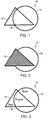
- FIG. 1 shows a computer illustration 10 that includes a circle 12 and a triangle 14.
- the circle 12 and triangle 14 are simple examples of artwork objects.
- An artwork object 12, 14 includes an outline shape (i.e., a path) and an appearance.
- the appearance may include a particular color, a type of shading, and/or a picture (i.e., a raster).
- each object appears on at least one layer.
- Objects at higher layers can block the visibility of objects at lower layers.
- These layers can be established by defining a painting order that describes a sequence for placing artwork objects in the illustration 10 (e.g., first paint the circle, then paint the triangle on top of the circle).
- Each object in the painting order essentially is given its own layer with objects earlier in the painting order appearing behind objects later in the order.
- an opaque artwork object 14 on a higher layer can hide portions of an artwork object 12 on a lower layer.
- artwork objects can exhibit some transparency. As shown in FIG. 3, when red triangle 14 has some degree of transparency, placing red triangle 14 on top of blue circle 12 produces a mixture of red and blue (e.g., purple) where triangle 14 overlaps circle 12. The more transparent the triangle 14, the more the appearance of the circle 12 dominates the appearance of the shared region 16. In this case, increased transparency of the triangle 14 produces a bluer intersection region 16. Similarly, decreased transparency of triangle 14 produces a redder intersection region 16.
- adding additional artwork objects 22, 24 can quickly complicate an illustration 10. For example, adding just two rectangles 22, 24 increased the number of intersection regions between objects from one to twelve. Each additional intersection represents an additional region that the software must process.
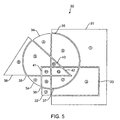
- FIG. 5 shows a planar map 30 produced by flattening the multiple layers in an illustration (e.g., illustration 10 in FIG. 4) into an equivalent single layer of opaque regions.
- FIG. 5 shows exaggerated seams between the regions 31-42 for illustrative purposes.
- a planar map 30 features interlocking non-overlapping regions 31-42.
- the appearance (e.g., a color, gradient, or raster) of each opaque region is determined such that outputting (e.g., sending to a printer or another program) the planar map regions is essentially indistinguishable from outputting the illustration objects directly. That is, instead of outputting each artwork object (e.g., circle 12, triangle 14, and rectangles 22 and 24 in FIG. 4), a system can output the path and appearance of each region 31-42 in the planar map.
- each artwork object e.g., circle 12, triangle 14, and rectangles 22 and 24 in FIG. 4
- Atomic regions are opaque illustration regions that are not intersected by other regions.
- the appearance of any atomic region is based on the appearances of the artwork objects covering the region in the original illustration (FIG. 4).
- FIG. 6 shows information that can be used to determine the appearance of different illustration regions.
- the information is in the form of a graph 50.
- the graph 50 includes a bottom portion 70 that features nodes, labelled "1" through "12", for each planar map region.
- Each node is the root of a binary tree that terminates in one or more leaves 62-68 corresponding to the illustration artwork objects.
- node "3" (corresponding to atomic region "3" 33 in the planar map of FIG. 5) is the root of a binary tree that includes pointers to children nodes "1" and "2".
- Nodes "1" and "2” in turn include pointers to artwork objects A 62 and B 64 (the rectangles in FIG. 4).
- Traversing the tree rooted by any node can be used to quickly determine the appearance of the node's planar map region.
- node "1" represents the appearance of artwork object A 62
- node "2" represents the appearance of artwork object B 64
- node "3" represents the composite appearance of artwork object B layered over artwork object A.
- the tree 70 acts as a pre-calculated set of indices that can be used dynamically to determine any represented region's appearance.
- each node can be pre-determined and stored for use as needed. Though this may be practical in the relatively simple illustration shown, the amount of memory needed for storage can swell as the illustration incorporates more artwork objects and the number of regions in the planar map grows.
- the tree 70 can be used to determine the appearance of each region dynamically.
- a system may produce an output stream that includes the path and appearance of each planar map region by making an on-the-fly determination of the region's appearance based on the region's tree 70 node.
- the system may discard each determined appearance after the appearance is sent into the output stream.
- the system can determine, output, and discard the appearance of node "1"; determine, output, and discard-the appearance of node "2"; then re-determine the appearance of nodes "1" and "2" to determine the appearance of node "3"; and so on.
- preservation of certain determined node appearances may speed display of an illustration without greatly increasing memory consumption. For example, nodes involved in the most number of determinations can be identified and these appearances can be preserved for future use instead of being discarded.
- the top portion of FIG. 6 includes an artwork tree 52 representing the transparencies of artwork objects.
- the top portion can be quickly consulted to determine artwork transparency when determining region appearances.
- the tree 52 includes a root node 54 and nodes 56-60 that specify transparency.
- the degree of transparency can be represented as a number such as an alpha value that ranges between 0 and 1.
- a transparency value of "1" represents a completely opaque object.
- a transparency value of "0" represents a completely transparent object.
- a node can describe the transparency of an individual object. For example, node 60 indicates that triangle D (14 in FIG. 4) has a transparency value of 0.4.
- a node can also describe the transparency of a group of objects.
- node 56 indicates that the group of circle C (12 in FIG. 4) and rectangle B (24 in FIG. 4) share a transparency value of 0.5.
- the group transparency value indicates the transparency of the group of objects as a collection, not the transparency of a particular object in the group. That is, the group of circle C and rectangle B will present the same transparent appearance relative to objects behind them, but the transparency of circle C relative to rectangle B is not affected by the group value.
- nodes for individual objects or other groups can have their own transparency values that are applied in addition to the transparency value of the group node.
- node 58 indicates that the circle C will have an additional transparency of 0.3 applied in addition to the transparency of 0.5 indicated by group node 48. Navigating up the tree from an artwork object node 62-68 to the root 54 can quickly produce transparency for any given artwork object.
- each node includes a reference to a transparency server that handles the different types and degrees of transparency.
- FIGS. 7-9 show one technique for constructing a planar map and graph 70 from a set of illustration artwork objects.
- FIG. 7 shows the first artwork object 31 in a paint order.
- the artwork object is added to the planar map along with a node (e.g., node "1") representing the appearance of the region covered by the artwork object.
- the second artwork object, rectangle B 33 adds a new region 32 and carves a region "3" out of previously existing region "1".
- the second artwork object is added to the planar map graph 70 along with a node for the region belonging solely to rectangle B 32 and a node "3" for the region 33 representing the layering of rectangle B over rectangle A.
- FIG. 7 shows the first artwork object 31 in a paint order.
- the artwork object is added to the planar map along with a node (e.g., node "1") representing the appearance of the region covered by the artwork object.
- the second artwork object, rectangle B 33 adds a new region 32 and carves
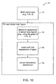
- the graph can be used to postpone determination of the appearance of a planar map regions until the appearance is to be included in an output stream.
- the process 70 handles each region in the planar map in turn. For each region, the process 70 determines the region's appearance 74 and sends 76 the determined appearance in an output stream along with the path of the region. The output stream may feed into memory of a printer. The process 70 then frees 78 memory used to describe the appearance of the region and begins processing the next region. This continues until each planar map region has been processed.
- a planar map can become very large for complex illustrations.
- a number of different techniques can reduce the size of the planar map. Some of these techniques can take advantage of functions provided by existing rasterization engines often present in illustration software such as Adobe® Illustrator®. Further, these techniques may be used in a wide variety of flattening schemes such as schemes that individually determine the appearance of each dot in an illustration.
- planar map involves identifying opaque objects that do not overlap areas covered by transparent objects. Intuitively, the appearance of such regions is that of the opaque object. Thus, the opaque object can be sent immediately to the output stream and without being added to the planar map.
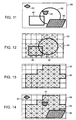
- FIG. 11 shows an illustration 80 that includes different opaque (shown as shaded) 82, 84, 86 and transparent 88, 90 artwork objects.
- opaque shown as shaded
- FIG. 11 shows an illustration 80 that includes different opaque (shown as shaded) 82, 84, 86 and transparent 88, 90 artwork objects.
- a wide variety of techniques can be used to identify those opaque objects (or portions of opaque objects) that do not overlap any transparent objects. For example, a process could test each opaque object against each transparent object to determine whether their paths intersect. The number of comparisons, however, increases geometrically with each additional artwork object.
- FIG. 12 illustrates a technique for quickly identifying opaque objects that do not intersect any transparent objects without a direct determination of intersection between different pairs of opaque and transparent objects.
- the technique maps transparent artwork objects 88, 90 to an off-screen low-resolution grid 92, (e.g., 32 x 32 cells).
- grid 92 does not imply a particular geometry of grid cells. That is, the grid 92 is merely a planar subdivision that can feature cells of a variety of geometries (e.g., squares, triangles, hexagons, and so forth). The portion of the grid 92 that includes any part of a transparent object is marked.
- this is performed by setting a rasterization engine's transform matrix to map bounding boxes of transparent objects to the low-resolution grid. As shown in FIG. 13, this marking produces a coarse approximation 94 of regions including transparent objects. Mapping an opaque object 82, 84, 86 to the low-resolution grid 92 quickly provides an estimate of whether any particular opaque object 82, 84, 86 overlaps any transparent objects. Because of the coarseness of the approximation of the transparent region 94, this approach will sometimes miscategorize an opaque object as overlapping the transparent region when no such overlap exists. However, the technique quickly identifies objects that do overlap the transparent region.
- This technique can be implemented using fast rasterization engine functions. For example, after painting the low-resolution grid (e.g., raster) white, the initial mapping of transparent objects to the low-resolution grid may be done by painting the transparent objects on the grid in black, for example, using an over-scanning flood-fill mode. The testing of whether an opaque object overlaps the transparency region may be performed using a rasterization engine blending mode function that checks a cell in the low-resolution grid and determines whether or not it has been previously painted black.
- a rasterization engine blending mode function that checks a cell in the low-resolution grid and determines whether or not it has been previously painted black.
- FIG. 15 shows one such process 72.
- the process 72 classifies 102 each opaque object based on its intersection, if any, with the transparency region.
- An opaque object may be completely inside the transparency region, partially inside, or completely outside the transparency region. Classifying an opaque object as being completely inside or completely outside requires analysis of the entire area covered by the opaque object. However, an opaque object can be immediately classified as being partially inside the transparency region once analysis of the region occupied by the opaque object yields at least one portion inside and one portion outside.
- the process 72 immediately outputs 108 the opaque object to the output stream without adding the artwork object to the planar map. If the opaque object is completely inside the transparency region, the process 105 adds the entire object to the planar map. If, however, the opaque object is partially inside and partially outside the transparency region, the process 72 can immediately send 104 the opaque object to the output stream and add 106 the opaque object to the planar map. Alternatively, the process can add only the portion of opaque object that is inside the transparency region to the planar map. In either case, portions of an illustration that do not require transparency processing to determine their appearance do not unnecessarily consume computer resources.
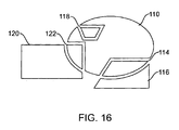
- FIG. 16 shows a planar map produced using the process 72 shown in FIG. 15.
- the planar map does not include any regions corresponding to opaque object 84,-but does include opaque object 86 in its entirety (shown as planar map region 118).
- the map also includes a portion of opaque object 88 clipped to the transparency region (shown as planar map regions 114 and 116).
- the technique of identifying opaque objects that overlap transparent objects may be used to improve a variety of different illustration flattening schemes. For example, opaque objects that do not overlap transparent objects may be added to a flattened raster without compositing each individual dot in the opaque object. Reducing the number of dots composited both speeds processing and reduces consumption of computer resources.
- a process can exclude artwork objects from flattening based on a determination that the object is obscured by an opaque object.
- an opaque object may be on an "higher" layer (i.e., conceptually closer to the screen) than objects beneath. Including the obscured artwork objects in a flattening process merely expends resources without altering the appearance of the output.
- An implementation to exclude obscured artwork from flattening may involve processing artwork objects layer by layer and progressively mapping out regions covered by opaque objects. As a transparent object is encountered in the layer by layer processing, a comparison may be made to determine if the transparent objects is completely (or partially) covered by a region mapped by one or more "higher" opaque objects. The covered portion may be excluded from the flattening process.
- an off-screen grid can be used to identify complex regions of an illustration.
- Some illustrations may feature areas having multiple objects in a very small space. These objects typically produce a large number of very small (e.g., pixel or sub-pixel sized) atomic regions. For these small spaces, it can be more efficient to determine the color value of each point individually (i.e., rasterize a small area) than add the very small atomic regions to the planar map.
- FIGS. 17-20 illustrate a technique for identifying complex regions of an illustration.
- FIG. 17 shows an illustration 130 of artwork objects 132-142. As shown, many of the objects 132-142 appear clustered near object 138.
- FIG. 18 shows a mapping of the artwork objects onto an off-screen low-resolution grid 144. The resolution of the grid 144 may be fixed or dynamically determined. Counting the number of objects having an outline in each grid cell can identify complex regions.
- FIG. 19 shows a count of objects whose paths enter each cell in the low-resolution grid. As shown, grid cell 146 is entered by objects 136-142 and has a value of "4". A threshold can identify those grid cells having highly complex geometry. For example, a user may define any cell having a value of "4" or more as being highly complex.
- a grid cell may be classified as a complex region and rasterized instead of adding objects in the cell into the planar map.
- the process may use different techniques to produce a threshold (e.g., set the threshold so that it includes the most complex 5% of grid cells).
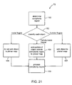
- FIG. 21 shows a process 72 for identifying complex regions of an illustration and processing objects that lie in the complex regions without use of the planar map.
- each object can be classified as being completely inside the complex region, partially inside, or completely outside the area. If completely inside, the object is not added 158 to the planar map. If completely outside, the object is added 157 to the planar map. If only partially inside, the entire object may be added to the planar map or, alternatively, only the portion of the object lying outside the complex region may be added to the planar map.
- the complex regions are then processed 159 (e.g., rasterized) for display independent of the processing for planar map regions.
- each artwork object may be drawn in the low-resolution grid using a pen having a thickness of "1" and a transparency alpha value near "0".
- stroking each object adds a value of "1” to each cell covered by the stroke and darkens the cell.
- An intersection blending mode can identify "dark" cells having a number of strokes that exceeds the user defined threshold.
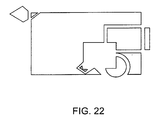
- FIG. 22 shows a planar map produced by the process of FIG. 19. As shown, object 138 is not represented in the planar map. Additionally, only portions of objects 136, 140, and 142 outside the complex regions appear in the planar map.
- this technique for quickly identifying complex regions of an illustration may be used in systems that use flattening techniques other than the planar map technique described above, for example, to reduce the number of object intersections that need to be handled by other flattening techniques.
- FIG. 23 shows a computer platform 170 suitable for implementing the techniques described above.
- the platform 170 can include an output device such as a monitor 172 or printer 186 for displaying an illustration 174.
- the platform may also include a keyboard 178 and/or pointing device 176.
- the platform includes a digital computer 180 that further includes a processor 182 and access a computer readable medium (e.g., Random Access Memory 184A, hard disk 184B, CD-ROM 184C, and/or floppy disk 184D).
- the memory can include instructions 186 that implement the techniques described herein. These instructions 186 are transferred to the processor 182 for execution in the course of operation.
- the techniques described here are not limited to any particular hardware, firmware, or software configuration; they may find applicability in any computing or processing environment.
- different embodiments can be used in different graphics environments.
- the disclosed invention can be used in a resolution-independent graphics environment that specifies artwork positioning using vectors and generates artwork coordinates when associated with a particular resolution.
- the techniques may be implemented in hardware or software, or a combination of any of them.
- the techniques are implemented in computer programs executing on programmable computers that each include a processor, a storage medium readable by the processor (including volatile and non-volatile memory and/or storage elements), at least one input device, and one or more output devices.
- Program code is applied to data entered using the input device to perform the functions described and to generate output information.
- the output information is applied to one or more output devices.
- Each program is preferably implemented in a high level procedural or object oriented programming language to communicate with a computer system.
- the programs can be implemented in assembly or machine language, if desired.
- the language may be a compiled or interpreted language.
- Each such computer program is preferable stored on a storage medium or device (e.g., CD-ROM, hard disk or magnetic diskette) that is readable by a general or special purpose programmable computer for configuring and operating the computer when the storage medium or device is read by the computer to perform the procedures described in this document.
- a storage medium or device e.g., CD-ROM, hard disk or magnetic diskette
- the system may also be considered to be implemented as a computer-readable storage medium, configured with a computer program, where the storage medium so configured causes a computer to operate in a specific and predefined manner.
Landscapes
- Physics & Mathematics (AREA)
- General Physics & Mathematics (AREA)
- Engineering & Computer Science (AREA)
- Theoretical Computer Science (AREA)
- Processing Or Creating Images (AREA)
- Image Generation (AREA)
- Image Processing (AREA)
Claims (34)
- Verfahren zur Verarbeitung bzw. Bearbeitung einer Computergraphikillustration (10), die überlappende Stücke bzw. Teile von Gestaltungsarbeit bzw. einer Druckvorlage (12, 14, 22, 24) aufweist, wobei jedes Stück der Gestaltungsarbeit ein Aussehen aufweist, wobei wenigstens ein Teil von wenigstens einem Stück der Gestaltungsarbeit einen Transparenzgrad aufweist, wobei das Verfahren umfaßt:dadurch gekennzeichnet, daßEinebenen bzw. Abflachen von wenigstens einigen der Stücke der Gestaltungsarbeit (12, 14, 22, 24) in nicht überlappende Bereiche bzw. Regionen (31 - 42);Speichern von Information, die beschreibt, wie die Aussehen von einem oder mehreren Stück(en) der Gestaltungsarbeit (12, 14, 22, 24) kombiniert werden können, um ein Aussehen für wenigstens einen der nicht überlappenden Bereiche zu bestimmen; Bestimmen (74) eines Aussehens für wenigstens einen der nicht überlappenden Bereiche (33) basierend auf der gespeicherten Information; undAusgeben (76) des bestimmten Aussehens,
die gespeicherte Information einen Graph bzw. ein Diagramm (50) enthält, welches(r) Knoten enthält, wobei jeder Knoten ein Aussehen eines entsprechenden, nicht überlappenden Bereichs darstellt bzw. repräsentiert, wobei jeder Knoten eine Wurzel eines Baums ist, welcher in einem oder mehreren Blättern (62, 64, 66, 68) endet, wobei jedes Blatt ein Aussehen eines entsprechenden der Stücke einer Gestaltungsarbeit (12, 14, 22 und 24) darstellt bzw. repräsentiert. - Verfahren nach Anspruch 1, wobei das Ausgeben ein Drucken umfaßt.
- Verfahren nach Anspruch 1, wobei das Einebenen ein Ausbilden bzw. Erzeugen einer ebenen bzw. planaren Karte (30) umfaßt, und wobei die nicht überlappenden Bereiche (31 - 42) ebene bzw. planare Kartenbereiche umfassen.
- Verfahren nach Anspruch 1, wobei die Information Information umfaßt, die beschreibt, wie die Aussehen von zwei oder mehreren anderen nicht überlappenden Bereichen (34, 38) kombiniert werden können, um ein Aussehen für einen der nicht überlappenden Bereiche (39) zu bestimmen.
- Verfahren nach Anspruch 1, weiters umfassend
ein Verwerfen (78) des bestimmten Aussehens eines nicht überlappenden Bereichs (31) vor einem Bestimmen (74) eines Aussehens eines unterschiedlichen, nicht überlappenden Bereichs (33). - Verfahren nach Anspruch 5, wobei das Verwerfen (78) vor dem Bestimmen (74) ein Verwerfen (78) vor dem Ausgeben (76) von jedem nicht überlappenden Bereich (31 - 42) umfaßt.
- Verfahren nach Anspruch 5, wobei das Verwerfen (78) das Freigeben bzw. Aufheben einer Zuordnung von dem Speicher (184A) umfaßt.
- Verfahren nach Anspruch 1, weiter umfassend
Auswählen von einem oder mehreren nicht überlappenden Bereichen (31 - 42);
nicht Verwerfen (78) des bestimmten Aussehens, wenn der Bereich einer der gewählten Bereiche ist; und
Verwerfen (78) des bestimmten Aussehens, wenn der Bereich nicht einer der gewählten Bereiche ist. - Verfahren nach Anspruch 1, wobei das Speichern von Information ein Konstruieren eines Gestaltungsarbeits- bzw. Druckvorlagenbaums (52) umfaßt, welcher Transparenzwerte für Stücke der Gestaltungsarbeit speichert.
- Verfahren nach Anspruch 9, worin der Gestaltungsarbeitbaum (52) Transparenzwerte für Gruppen von Stücken der Gestaltungsarbeit speichert.
- Verfahren nach Anspruch 1, wobei das Einebenen von wenigstens einem der Stücke der Gestaltungsarbeit (12, 14, 22, 24) ein Bestimmen umfaßt, ob ein Stück der Gestaltungsarbeit oder ein Abschnitt eines Stücks der Gestaltungsarbeit in dem Einebenen umfaßt ist.
- Verfahren nach Anspruch 11, wobei das Bestimmen, ob zu umfassen bzw. enthalten ist, ein Bestimmen umfaßt, ob ein Stück einer Gestaltungsarbeit (12, 14, 22, 24) eine Fläche der Illustration (10) abdeckt, die auch durch eines oder mehrere Stücke der Gestaltungsarbeit abgedeckt ist, die einen Transparenzgrad (14) aufweist.
- Verfahren nach Anspruch 12, wobei das Bestimmen, ob ein Stück einer Gestaltungsarbeit (12, 14, 22, 24) abdeckt, umfaßt
Aufzeichnen bzw. Kartographieren (100) von Flächen der Illustration (10), die durch Stücke der Gestaltungsarbeit abgedeckt sind, die einen Grad an Transparenz (14) aufweisen; und
Bestimmen (102), ob ein opakes Stück einer Gestaltungsarbeit (12) wenigstens einen Abschnitt der aufgezeichneten Bereiche überlappt. - Verfahren nach Anspruch 13, wobei das Aufzeichnen (100) ein Erzeugen einer Karte bzw. eines Plans eines Off-Screen-Rasters (92) umfaßt.
- Verfahren nach Anspruch 14, wobei das Aufzeichnen (100) ein Verwenden einer Rasterbildungsmaschine umfaßt, um Bereiche bzw. Flächen des Off-Screen-Rasters (92) zu markieren.
- Verfahren nach Anspruch 13, weiters umfassend ein Bearbeiten des opaken Stücks einer Gestaltungsarbeit (12) basierend auf dem Grad der Überlappung mit der Karte.
- Verfahren nach Anspruch 11, wobei das Bestimmen, ob aufzunehmen bzw. zu enthalten ist, ein Beinhalten (105) eines opaken Stücks einer Gestaltungsarbeit (12) umfaßt, das vollständig innerhalb des aufgezeichneten Bereichs liegt.
- Verfahren nach Anspruch 11, wobei das Bestimmen, ob zu enthalten ist, ein Beinhalten (106) eines Abschnitts eines opaken Stücks einer Gestaltungsarbeit (12) innerhalb des aufgezeichneten Bereichs umfaßt.
- Verfahren nach Anspruch 11, wobei das Ausgeben ein Ausgeben (108) eines opaken Stücks einer Gestaltungsarbeit (12) außerhalb des aufgezeichneten Bereichs umfaßt.
- Verfahren nach Anspruch 11, wobei das Bestimmen, ob zu enthalten ist, umfaßt Identifizieren (150) von einem oder mehreren komplexen Bereich(en) der Illustration (10); und
Bestimmen (152), ob ein Stück einer Gestaltungsarbeit (12, 14, 22, 24) irgendeinen von dem einen oder den mehreren komplexen Bereich(en) überlappt. - Verfahren nach Anspruch 20, wobei das Identifizieren (150) von einem oder mehreren komplexen Bereich(en) ein Identifizieren von einem oder mehreren Bereich(en) umfaßt, der (die) eine Anzahl von Pfaden aufweist(en), die durch jeden des einen oder der mehreren Bereichs(e) hindurchgehen, welche einen Schwellwert überschreiten.
- Verfahren nach Anspruch 20, wobei das Identifizieren (150) eines komplexen Bereichs ein Streichen bzw. Nachziehen der Pfade der Stücke einer Gestaltungsarbeit (12, 14, 22, 24) auf einem Off-Screen-Raster (92) umfaßt.
- Verfahren nach Anspruch 20, weiters umfassend ein Bearbeiten eines Stücks einer Gestaltungsarbeit (12, 14, 22, 24) basierend auf seinem Grad einer Überlappung mit einem komplexen Bereich.
- Verfahren nach Anspruch 20, weiters umfassend ein Rasterbilden des komplexen Bereichs und ein Ausgeben der Rasterfläche bzw. der mit Raster versehenen Fläche.
- Verfahren nach Anspruch 20, wobei ein Bestimmen, ob zu enthalten ist, ein Beinhalten (157) von Stücken einer Gestaltungsarbeit außerhalb von komplexen Bereichen umfaßt.
- Verfahren nach Anspruch 1, wobei die nicht überlappenden Bereiche (31 - 42) Bereiche einer ebenen Karte (30) sind, wobei das Verfahren weiters umfaßt für wenigstens einige der Bereiche der ebenen Karte (30):Bestimmen (74) eines Bereichsaussehens;Ausgeben (76) des bestimmten Aussehens für den Bereich; undVerwerfen (78) des gespeicherten Aussehens, bevor das Aussehen eines unterschiedlichen nicht überlappenden Bereichs bestimmt wird.
- Verfahren nach Anspruch 26, weiters umfassend
Identifizieren (102) von einen oder mehreren opaken Gestaltungsarbeit- bzw. Druckvorlagengegenständen bzw. -objekten, welche nicht Gestaltungsarbeitgegenstände überlappen, die einen Grad an Transparenz besitzen; und
Ausschließen (108) des einen oder der mehreren identifizierten opaken Gestaltungsarbeitgegenstands (-stände) von der ebenen bzw. planaren Karte (30). - Verfahren nach Anspruch 26, weiters umfassend
Bestimmen (150) von einem oder mehreren komplexen Bereich(en) der Illustration;
Identifizieren (152) von Gestaltungsarbeitgegenständen, die Pfade vollständig innerhalb des bestimmten komplexen Bereichs aufweisen; und
Ausschließen (158) der identifizierten Gestaltungsarbeitgegenstände von der ebenen Karte (30). - Computerprogrammprodukt, das auf einem computer-lesbaren Medium angeordnet ist, um eine Computergraphikillustration (10) zu bearbeiten bzw. zu verarbeiten, die überlappende Stücke einer Gestaltungsarbeit bzw. Druckvorlage (12, 14, 22, 24) aufweisen, wobei jedes Stück einer Gestaltungsarbeit ein Aussehen aufweist, wobei wenigstens ein Teil von wenigstens einem Stück einer Gestaltungsarbeit einen Transparenzgrad aufweist, wobei das Computerprogramm Instruktionen zum Veranlassen des Prozessors aufweist, um:dadurch gekennzeichnet, daßwenigstens einige der Stücke einer Gestaltungsarbeit (12, 14, 22, 24) in nicht überlappende Bereiche (31 - 42) abzuflachen bzw. einzuebnen;Information zu speichern, die beschreibt, wie die Aussehen des einen oder der mehreren Stücks (Stücke) einer Gestaltungsarbeit (12, 14, 22, 24) kombiniert werden können, um ein Aussehen für einen gegebenen der nicht überlappenden Bereiche (31 - 42) zu bestimmen,ein Aussehen für wenigstens einen der nicht überlappenden Bereiche (33) basierend auf der gespeicherten Information zu bestimmen (74); unddas bestimmte Aussehen auszugeben (76),
die gespeicherte Information einen Graph bzw. ein Diagramm (50) enthält, welcher(s) Knoten enthält, wobei jeder Knoten ein Aussehen eines entsprechenden nicht überlappenden Bereichs darstellt bzw. repräsentiert, wobei jeder Knoten eine Wurzel eines Baums ist, welcher in einem oder mehreren Blatt (Blättern) (62, 64, 66, 68) endet, wobei jedes Blatt ein Aussehen eines entsprechenden der Stücke einer Gestaltungsarbeit (12, 14, 22, 24) darstellt bzw. repräsentiert. - Computerprogrammprodukt nach Anspruch 29, wobei das Einebenen von wenigstens einigen der Stücke einer Gestaltungsarbeit (12, 22, 22, 24) ein Bestimmen umfaßt, ob Stücke einer Gestaltungsarbeit oder Bereiche von Stücken einer Gestaltungsarbeit in dem Einebenen aufzunehmen sind.
- Computerprogrammprodukt nach Anspruch 30, wobei das Bestimmen, ob zu enthalten ist, ein Aufzeichnen (100) von Stücken einer Gestaltungsarbeit (12, 14, 22, 24) in einem Off-Screen-Raster (92) umfaßt.
- Computerprogrammprodukt nach Anspruch 30, wobei das Bestimmen, ob zu enthalten ist, ein Bestimmen (150) von komplexen Flächen bzw. Bereichen der Darstellung bzw. Illustration und ein Ausschließen (158) von Stücken einer Gestaltungsarbeit (12, 14, 22, 24) innerhalb der komplexen Bereiche von dem Einebenen umfaßt.
- Computerprogrammprodukt nach Anspruch 30, wobei das Bestimmen, ob zu enthalten ist, ein Bestimmen (102) eines opaken Stücks einer Gestaltungsarbeit, welches nicht eine transparente Gestaltungsarbeit überlappt, und ein Ausschließen (108) einer derartigen opaken Gestaltungsarbeit von dem Einebenen umfaßt.
- Computerprogrammprodukt nach Anspruch 29, wobei das Abflachen ein Konstruieren einer ebenen bzw. planaren Karte (30) umfaßt.
Applications Claiming Priority (2)
| Application Number | Priority Date | Filing Date | Title |
|---|---|---|---|
| US444778 | 1982-11-26 | ||
| US09/444,778 US6720977B1 (en) | 1999-11-22 | 1999-11-22 | Processing illustration artwork |
Publications (3)
| Publication Number | Publication Date |
|---|---|
| EP1104918A2 EP1104918A2 (de) | 2001-06-06 |
| EP1104918A3 EP1104918A3 (de) | 2003-04-02 |
| EP1104918B1 true EP1104918B1 (de) | 2005-05-04 |
Family
ID=23766322
Family Applications (1)
| Application Number | Title | Priority Date | Filing Date |
|---|---|---|---|
| EP00310380A Expired - Lifetime EP1104918B1 (de) | 1999-11-22 | 2000-11-22 | System für die Verarbeitung von Stücken in der Gestaltungsarbeit |
Country Status (4)
| Country | Link |
|---|---|
| US (1) | US6720977B1 (de) |
| EP (1) | EP1104918B1 (de) |
| JP (1) | JP2001188915A (de) |
| DE (1) | DE60019879T2 (de) |
Families Citing this family (23)
| Publication number | Priority date | Publication date | Assignee | Title |
|---|---|---|---|---|
| US6690470B1 (en) * | 1999-11-04 | 2004-02-10 | Arcturus Engineering, Inc. | Automated laser capture microdissection |
| US6894704B1 (en) | 1999-11-22 | 2005-05-17 | Adobe Systems Incorporated | Processing complex regions of illustration artwork |
| US7006711B2 (en) * | 2000-06-21 | 2006-02-28 | Microsoft Corporation | Transform table for ink sizing and compression |
| US7397949B2 (en) * | 2000-06-21 | 2008-07-08 | Microsoft Corporation | Serial storage of ink and its properties |
| US6707473B2 (en) * | 2001-08-01 | 2004-03-16 | Microsoft Corporation | Dynamic rendering of ink strokes with transparency |
| US6943809B2 (en) | 2001-06-12 | 2005-09-13 | Adobe Systems Incorporated | Tiled vector flattened output |
| US7343053B2 (en) * | 2001-06-27 | 2008-03-11 | Microsoft Corporation | Transform table for ink sizing and compression |
| US6909430B2 (en) * | 2001-08-01 | 2005-06-21 | Microsoft Corporation | Rendering ink strokes of variable width and angle |
| US7168038B2 (en) * | 2001-08-01 | 2007-01-23 | Microsoft Corporation | System and method for scaling and repositioning drawings |
| US7209258B1 (en) | 2002-05-21 | 2007-04-24 | Adobe Systems Incorporated | Complexity-based transparency flattening |
| US7181687B2 (en) * | 2002-06-27 | 2007-02-20 | Adobe Systems Incorporated | Previewing the effects of flattening transparency |
| US8036475B2 (en) * | 2002-12-13 | 2011-10-11 | Ricoh Co., Ltd. | Compression for segmented images and other types of sideband information |
| US8769395B2 (en) * | 2002-12-13 | 2014-07-01 | Ricoh Co., Ltd. | Layout objects as image layers |
| US7262782B1 (en) | 2003-11-07 | 2007-08-28 | Adobe Systems Incorporated | Selectively transforming overlapping illustration artwork |
| WO2005106797A1 (en) | 2004-05-05 | 2005-11-10 | Kodak Graphic Communication Canada Company | System and methods for color matching overprinted documents |
| US7646386B2 (en) * | 2005-04-19 | 2010-01-12 | Adobe Systems Incorporated | Modifying a path in a drawing |
| US7256785B1 (en) * | 2005-04-19 | 2007-08-14 | Adobe Systems Incorporated | Assigning subpath attributes in a drawing |
| US7502028B1 (en) * | 2005-04-19 | 2009-03-10 | Adobe Systems Incorporated | Assigning region attributes in a drawing |
| US7969604B2 (en) * | 2005-11-30 | 2011-06-28 | Adobe Systems Incorporated | Systems and methods for printing artwork containing transparency |
| US8139263B2 (en) * | 2005-11-30 | 2012-03-20 | Adobe Systems Incorporated | Systems and methods for printing artwork containing overlapped inks |
| US7583410B1 (en) | 2005-12-13 | 2009-09-01 | Adobe Systems Incorporated | System to create image transparency in a file generated utilizing a print stream |
| US8181220B2 (en) | 2005-12-19 | 2012-05-15 | Adobe Systems Incorporated | Method and apparatus for digital rights management policies |
| US7616203B1 (en) * | 2006-01-20 | 2009-11-10 | Adobe Systems Incorporated | Assigning attributes to regions across frames |
Family Cites Families (26)
| Publication number | Priority date | Publication date | Assignee | Title |
|---|---|---|---|---|
| US4769636A (en) * | 1985-08-14 | 1988-09-06 | Hitachi, Ltd. | Display control method for multi-window system |
| FR2646256A1 (fr) * | 1989-04-24 | 1990-10-26 | Digital Equipment Int | Procede pour realiser des dessins a l'aide d'un ordinateur |
| JP2837514B2 (ja) * | 1990-06-19 | 1998-12-16 | 富士通株式会社 | 画像編集装置 |
| US5390291A (en) * | 1990-10-05 | 1995-02-14 | Atlantic Richfield Company | Method for interpolating between two regions of a display |
| DE69225544T2 (de) | 1991-08-13 | 1998-12-03 | Xerox Corp | Elektronische Bilderzeugung |
| US5509110A (en) * | 1993-04-26 | 1996-04-16 | Loral Aerospace Corporation | Method for tree-structured hierarchical occlusion in image generators |
| US5592597A (en) * | 1994-02-14 | 1997-01-07 | Parametric Technology Corporation | Real-time image generation system for simulating physical paint, drawing media, and feature modeling with 3-D graphics |
| AUPM704194A0 (en) * | 1994-07-25 | 1994-08-18 | Canon Information Systems Research Australia Pty Ltd | Efficient methods for the evaluation of a graphical programming language |
| AUPM704594A0 (en) * | 1994-07-25 | 1994-08-18 | Canon Information Systems Research Australia Pty Ltd | Efficient methods for the compositing of graphical elements |
| AUPM822394A0 (en) * | 1994-09-16 | 1994-10-13 | Canon Inc. | Object based rendering system |
| US5659767A (en) | 1994-11-10 | 1997-08-19 | Canon Information Systems, Inc. | Application programming interface for accessing document analysis functionality of a block selection program |
| US5680526A (en) * | 1995-06-06 | 1997-10-21 | Apple Computer, Inc. | Method and system for selectively rendering image data in a bi-level or multi-level format |
| US5977979A (en) * | 1995-10-31 | 1999-11-02 | International Business Machines Corporation | Simulated three-dimensional display using bit-mapped information |
| JP2910649B2 (ja) * | 1995-12-28 | 1999-06-23 | 富士ゼロックス株式会社 | 画像形成装置および画像形成方法 |
| US5926185A (en) * | 1996-05-03 | 1999-07-20 | Barco Graphics N.V. | Method for processing a set of page description language commands to reduce complexity |
| TW342487B (en) * | 1996-10-03 | 1998-10-11 | Winbond Electronics Corp | Fully overlay function device and method |
| US5818975A (en) * | 1996-10-28 | 1998-10-06 | Eastman Kodak Company | Method and apparatus for area selective exposure adjustment |
| US5923333A (en) * | 1997-01-06 | 1999-07-13 | Hewlett Packard Company | Fast alpha transparency rendering method |
| US6031544A (en) * | 1997-02-28 | 2000-02-29 | Adobe Systems Incorporated | Vector map planarization and trapping |
| US6043824A (en) * | 1997-06-27 | 2000-03-28 | Xerox Corporation | Composing layered synthetic graphics filters with limited scopes of operation |
| US6072501A (en) * | 1997-06-27 | 2000-06-06 | Xerox Corporation | Method and apparatus for composing layered synthetic graphics filters |
| US5912674A (en) * | 1997-11-03 | 1999-06-15 | Magarshak; Yuri | System and method for visual representation of large collections of data by two-dimensional maps created from planar graphs |
| US6049339A (en) | 1997-12-22 | 2000-04-11 | Adobe Systems Incorporated | Blending with planar maps |
| US6437796B2 (en) * | 1998-02-17 | 2002-08-20 | Sun Microsystems, Inc. | Multiple processor visibility search system and method |
| US6356274B1 (en) * | 1999-01-25 | 2002-03-12 | Donald Spector | Computer system for converting a colored picture into a color-in line drawing |
| US6359635B1 (en) * | 1999-02-03 | 2002-03-19 | Cary D. Perttunen | Methods, articles and apparatus for visibly representing information and for providing an input interface |
-
1999
- 1999-11-22 US US09/444,778 patent/US6720977B1/en not_active Expired - Lifetime
-
2000
- 2000-11-22 DE DE60019879T patent/DE60019879T2/de not_active Expired - Lifetime
- 2000-11-22 JP JP2000356696A patent/JP2001188915A/ja active Pending
- 2000-11-22 EP EP00310380A patent/EP1104918B1/de not_active Expired - Lifetime
Also Published As
| Publication number | Publication date |
|---|---|
| US6720977B1 (en) | 2004-04-13 |
| EP1104918A3 (de) | 2003-04-02 |
| JP2001188915A (ja) | 2001-07-10 |
| DE60019879D1 (de) | 2005-06-09 |
| EP1104918A2 (de) | 2001-06-06 |
| DE60019879T2 (de) | 2006-02-16 |
Similar Documents
| Publication | Publication Date | Title |
|---|---|---|
| US7495675B1 (en) | Processing illustration artwork | |
| US6515675B1 (en) | Processing opaque pieces of illustration artwork | |
| US6720977B1 (en) | Processing illustration artwork | |
| EP0924653B1 (de) | Verfahren und Anordnung zum Mischen von graphischen Objekten mit Planarkarten | |
| EP0910044B1 (de) | Verfahren und Vorrichtung zur Komposition von Bildfarben unter Speicherbeschränkungen | |
| KR960016886B1 (ko) | 다수의 3차원 객체로부터 가시 객체를 픽크하는 장치 및 방법과 그를 이용한 비디오 디스플레이 시스템 | |
| EP0691012B1 (de) | Graphisches kantensystem | |
| JP4101275B2 (ja) | 走査線ベースのラスタ画像プロセッサにおける奥行き追跡の方法 | |
| EP1025558B1 (de) | Verfahren und anordnung zur ausführung von farbschlüsseln, transparenz und nebelfunktionen | |
| US6828985B1 (en) | Fast rendering techniques for rasterised graphic object based images | |
| CA2233814C (en) | Method and apparatus for composing layered synthetic graphics filters | |
| US7692652B2 (en) | Selectively transforming overlapping illustration artwork | |
| US20250124641A1 (en) | Method and system of decoupled object space shading | |
| US6906715B1 (en) | Shading and texturing 3-dimensional computer generated images | |
| US20020135587A1 (en) | System and method for implementing accumulation buffer operations in texture mapping hardware | |
| EP1058912B1 (de) | Antialiasing mit unterabtastung für textur-raender | |
| US20030122821A1 (en) | Overlapping triangle meshes | |
| AU744091B2 (en) | Processing graphic objects for fast rasterised rendering | |
| AU743218B2 (en) | Fast renering techniques for rasterised graphic object based images | |
| AU2002318784B2 (en) | Overlapping Triangle Meshes | |
| Laib et al. | Integrating solid image capability into a general purpose calligraphic graphics package |
Legal Events
| Date | Code | Title | Description |
|---|---|---|---|
| PUAI | Public reference made under article 153(3) epc to a published international application that has entered the european phase |
Free format text: ORIGINAL CODE: 0009012 |
|
| AK | Designated contracting states |
Kind code of ref document: A2 Designated state(s): AT BE CH CY DE DK ES FI FR GB GR IE IT LI LU MC NL PT SE TR |
|
| AX | Request for extension of the european patent |
Free format text: AL;LT;LV;MK;RO;SI |
|
| PUAL | Search report despatched |
Free format text: ORIGINAL CODE: 0009013 |
|
| RIC1 | Information provided on ipc code assigned before grant |
Ipc: 7G 06T 11/60 B Ipc: 7G 06T 11/00 A |
|
| AK | Designated contracting states |
Kind code of ref document: A3 Designated state(s): AT BE CH CY DE DK ES FI FR GB GR IE IT LI LU MC NL PT SE TR |
|
| AX | Request for extension of the european patent |
Extension state: AL LT LV MK RO SI |
|
| 17P | Request for examination filed |
Effective date: 20030909 |
|
| AKX | Designation fees paid |
Designated state(s): DE GB |
|
| 17Q | First examination report despatched |
Effective date: 20040109 |
|
| GRAP | Despatch of communication of intention to grant a patent |
Free format text: ORIGINAL CODE: EPIDOSNIGR1 |
|
| GRAS | Grant fee paid |
Free format text: ORIGINAL CODE: EPIDOSNIGR3 |
|
| GRAA | (expected) grant |
Free format text: ORIGINAL CODE: 0009210 |
|
| AK | Designated contracting states |
Kind code of ref document: B1 Designated state(s): DE GB |
|
| REG | Reference to a national code |
Ref country code: GB Ref legal event code: FG4D |
|
| REG | Reference to a national code |
Ref country code: IE Ref legal event code: FG4D |
|
| REF | Corresponds to: |
Ref document number: 60019879 Country of ref document: DE Date of ref document: 20050609 Kind code of ref document: P |
|
| PLBE | No opposition filed within time limit |
Free format text: ORIGINAL CODE: 0009261 |
|
| STAA | Information on the status of an ep patent application or granted ep patent |
Free format text: STATUS: NO OPPOSITION FILED WITHIN TIME LIMIT |
|
| 26N | No opposition filed |
Effective date: 20060207 |
|
| REG | Reference to a national code |
Ref country code: DE Ref legal event code: R082 Ref document number: 60019879 Country of ref document: DE Representative=s name: MUELLER-BORE & PARTNER PATENTANWAELTE PARTG MB, DE Ref country code: DE Ref legal event code: R081 Ref document number: 60019879 Country of ref document: DE Owner name: ADOBE INC., SAN JOSE, US Free format text: FORMER OWNER: ADOBE SYSTEMS, INC., SAN JOSE, CALIF., US |
|
| PGFP | Annual fee paid to national office [announced via postgrant information from national office to epo] |
Ref country code: DE Payment date: 20191127 Year of fee payment: 20 |
|
| PGFP | Annual fee paid to national office [announced via postgrant information from national office to epo] |
Ref country code: GB Payment date: 20191127 Year of fee payment: 20 |
|
| REG | Reference to a national code |
Ref country code: DE Ref legal event code: R071 Ref document number: 60019879 Country of ref document: DE |
|
| REG | Reference to a national code |
Ref country code: GB Ref legal event code: PE20 Expiry date: 20201121 |
|
| PG25 | Lapsed in a contracting state [announced via postgrant information from national office to epo] |
Ref country code: GB Free format text: LAPSE BECAUSE OF EXPIRATION OF PROTECTION Effective date: 20201121 |