EP1104940A1 - Organe d'actionnement à l' état solide , plus particulierement organe d'actionnenment pièzoélectrique - Google Patents
Organe d'actionnement à l' état solide , plus particulierement organe d'actionnenment pièzoélectrique Download PDFInfo
- Publication number
- EP1104940A1 EP1104940A1 EP99123924A EP99123924A EP1104940A1 EP 1104940 A1 EP1104940 A1 EP 1104940A1 EP 99123924 A EP99123924 A EP 99123924A EP 99123924 A EP99123924 A EP 99123924A EP 1104940 A1 EP1104940 A1 EP 1104940A1
- Authority
- EP
- European Patent Office
- Prior art keywords
- actuator
- solid state
- cooling
- mass
- cooling finger
- Prior art date
- Legal status (The legal status is an assumption and is not a legal conclusion. Google has not performed a legal analysis and makes no representation as to the accuracy of the status listed.)
- Withdrawn
Links
- 239000007787 solid Substances 0.000 title claims description 18
- 238000001816 cooling Methods 0.000 claims abstract description 52
- 239000011248 coating agent Substances 0.000 claims 1
- 238000000576 coating method Methods 0.000 claims 1
- 239000000463 material Substances 0.000 abstract description 12
- 230000017525 heat dissipation Effects 0.000 description 9
- RYGMFSIKBFXOCR-UHFFFAOYSA-N Copper Chemical compound [Cu] RYGMFSIKBFXOCR-UHFFFAOYSA-N 0.000 description 7
- 229910052802 copper Inorganic materials 0.000 description 7
- 239000010949 copper Substances 0.000 description 7
- 239000007788 liquid Substances 0.000 description 6
- 239000000919 ceramic Substances 0.000 description 5
- XAGFODPZIPBFFR-UHFFFAOYSA-N aluminium Chemical compound [Al] XAGFODPZIPBFFR-UHFFFAOYSA-N 0.000 description 3
- 229910052782 aluminium Inorganic materials 0.000 description 3
- 238000009413 insulation Methods 0.000 description 3
- 238000009825 accumulation Methods 0.000 description 2
- 239000004020 conductor Substances 0.000 description 2
- 239000002826 coolant Substances 0.000 description 2
- 229910052709 silver Inorganic materials 0.000 description 2
- 239000004332 silver Substances 0.000 description 2
- BQCADISMDOOEFD-UHFFFAOYSA-N Silver Chemical compound [Ag] BQCADISMDOOEFD-UHFFFAOYSA-N 0.000 description 1
- 239000000853 adhesive Substances 0.000 description 1
- 230000001070 adhesive effect Effects 0.000 description 1
- 230000002411 adverse Effects 0.000 description 1
- 229910010293 ceramic material Inorganic materials 0.000 description 1
- 230000008878 coupling Effects 0.000 description 1
- 238000010168 coupling process Methods 0.000 description 1
- 238000005859 coupling reaction Methods 0.000 description 1
- 238000013016 damping Methods 0.000 description 1
- 230000005284 excitation Effects 0.000 description 1
- 230000001771 impaired effect Effects 0.000 description 1
- 239000003921 oil Substances 0.000 description 1
- 230000009467 reduction Effects 0.000 description 1
- 229910052594 sapphire Inorganic materials 0.000 description 1
- 239000010980 sapphire Substances 0.000 description 1
- 229910000679 solder Inorganic materials 0.000 description 1
- 238000005476 soldering Methods 0.000 description 1
- 238000001757 thermogravimetry curve Methods 0.000 description 1
- 230000007704 transition Effects 0.000 description 1
Images


Classifications
-
- H—ELECTRICITY
- H10—SEMICONDUCTOR DEVICES; ELECTRIC SOLID-STATE DEVICES NOT OTHERWISE PROVIDED FOR
- H10N—ELECTRIC SOLID-STATE DEVICES NOT OTHERWISE PROVIDED FOR
- H10N30/00—Piezoelectric or electrostrictive devices
- H10N30/80—Constructional details
-
- H—ELECTRICITY
- H10—SEMICONDUCTOR DEVICES; ELECTRIC SOLID-STATE DEVICES NOT OTHERWISE PROVIDED FOR
- H10N—ELECTRIC SOLID-STATE DEVICES NOT OTHERWISE PROVIDED FOR
- H10N30/00—Piezoelectric or electrostrictive devices
- H10N30/50—Piezoelectric or electrostrictive devices having a stacked or multilayer structure
-
- H—ELECTRICITY
- H10—SEMICONDUCTOR DEVICES; ELECTRIC SOLID-STATE DEVICES NOT OTHERWISE PROVIDED FOR
- H10N—ELECTRIC SOLID-STATE DEVICES NOT OTHERWISE PROVIDED FOR
- H10N30/00—Piezoelectric or electrostrictive devices
- H10N30/50—Piezoelectric or electrostrictive devices having a stacked or multilayer structure
- H10N30/503—Piezoelectric or electrostrictive devices having a stacked or multilayer structure having a non-rectangular cross-section in a plane orthogonal to the stacking direction, e.g. polygonal or circular in top view
-
- H—ELECTRICITY
- H10—SEMICONDUCTOR DEVICES; ELECTRIC SOLID-STATE DEVICES NOT OTHERWISE PROVIDED FOR
- H10N—ELECTRIC SOLID-STATE DEVICES NOT OTHERWISE PROVIDED FOR
- H10N35/00—Magnetostrictive devices
- H10N35/80—Constructional details
Definitions
- the invention relates to a solid-state actuator, which with one in at least one spatial direction working actuator mass is provided, an electrode arrangement or Arrangement of excitation devices acts on the actuator mass to make a movement to initiate.
- a device for dissipating heat is provided in this solid state actuator according to the preamble of claim 1 .
- Solid state actuators are used to perform certain movements, for example to vibrate objects or the vibrational states of objects to dampen. Solid state actuators are particularly fast Actuators can be used in a wide range of applications, especially when movements to be carried out with a high force and medium to high frequencies to be executed.
- piezoceramic materials have remarkable mechanical performances can achieve range losses even at relatively low temperatures and suffer performance losses. Temperatures of 100 ° C are already suitable for severely impair the performance of an actuator. Temperatures of 100 ° C within a middle piezo actuator stack are, however, already comparatively low operating frequencies reached and therefore it has already various in the prior art Efforts have been made to convert the heat dissipation of a piezo actuator into heat to compensate.
- Electrostrictive ceramics are only in a narrow temperature range (e.g. +/- 10 ° C around Room temperature) effective, so that any further temperature drift is disadvantageous.
- a proposed solution is known, according to which a solid piezo actuator stack with a Air blower cooling or liquid cooling is provided to prevent heat build-up dissipate.
- a solid piezo actuator stack with a Air blower cooling or liquid cooling is provided to prevent heat build-up dissipate.
- the piezoceramic materials are extremely bad
- Such measures have thermal conductivity coefficients already in ceramic Piezo stack actuators with medium size are very limited in their success and fail large-volume piezo actuators.
- the technical effort especially at the use of liquid cooling, but also when using air cooling quite enormous and ultimately also leads to the actuator not being closed System can be formed, but connected to cooling lines or the like must become.
- the actuator must be cooled on its outer surface, which is particularly effective through liquid can be isolated very well. In spite of good insulation, rollovers occur even with medium operating powers and operating frequencies of an actuator, which the Destroy actuator.
- the actuator needs a technical environment that is used to dissipate the heat, i.e. Coolant lines, coolant pumps or the like.
- adefingers as a heat-dissipating measure for very extraordinary performance increases even with large actuators and in particular piezoceramic actuators or Leads actuator stacking.
- performance increases from the 5th achieve up to 10 times the otherwise achievable performance.
- Rods made of highly thermally conductive materials can be considered as cooling fingers, such as such as copper, aluminum, silver, sapphire or the like. It is also conceivable to have one To allow heat conduction to take place via a so-called heat pipe. Such are known to be Heat pipes partially evacuated pipes within which due to the large range and Mobility of the gas atoms or gas molecules, especially for heat transport are suitable.
- a piezo actuator changes dimensions and / or force. He can especially when actuated, also contract, i.e. not just expand, but Perform length changes or dimensional changes. Also changes in diameter are possible.
- actuators that are not built up as a stack, e.g. Piezo tubes. If In the present case, the term actuator stack is used, so is generally any form meant by actuator, i.e. any excitable structure (e.g. tube). The main case are but the stacks.
- the actuator mass can have only one recess or axial central bore, in which the cooling finger is then inserted. On the other hand, it is also possible to use an actuator mass to equip several recesses or bores.
- a corresponding solid-state actuator can also be designed in this way be that the cooling finger surrounds the actuator mass, i.e. the cooling finger has a recess or bore, the actuator mass in this recess or bore plugged.
- a heat transfer medium can be provided by actuator masses.
- This heat transfer medium should be at least essentially in the direction of propagation of the actuator mass be non-positive.
- Conventional thermal adhesive, thermal rubber, Thermal pastes or insulation oils significantly increase heat dissipation and Materials specially designed for this purpose can affect the performance of a influence the corresponding actuator extremely positively again.
- Certain types of Cold fingers, which are made of copper, for example, can still be coated be provided with high heat conduction, which is at least essentially not oxidized or corroded and in particular not with the heat transfer medium responds. Even thin layers of oxide can significantly increase heat transfer restrict and lead to enormous reductions in performance.
- the cooling finger or fingers are also very good heat conductors Base arranged, which are also made of copper or a comparable good thermal conductivity Material can be made.
- the base itself can be attached to another Heat dissipation arrangement can be connected, for example a plurality of cooling fins or the like, which can then dissipate the heat to the environment.
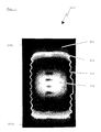
- FIG. 1 shows a thermographic record of a piezoelectric stack actuator 300.
- the actuator is cylindrical and the cylinder axis extends in the largest visible direction of propagation of the actuator 300. ends of the actuator 300 which with the Reference numerals 302 are difficult to see because they are thermally on a are low level.
- the regions 304, 306 of the actuator stack 300 are also on one thermally low level while in the central area 308 a high temperature prevails.
- the transition areas between the light containment area 304, 306 and the hot core area 308 are getting hotter.
- the possible final dimensions of the actuator stack 300 are indicated by the reference numerals 309a, 309b identified.
- the areas 302, 304, 306 are cool while area 308 represents a hot actuator core, but this is in the black and white representation 1 is not recognizable.
- the one designated by reference number 308 hot core of the actuator stack 300 is no longer able to provide an essential one To contribute to the overall performance of the actuator 300.
- FIG. 2 A first embodiment according to the invention can be seen in FIG. 2.
- An actuator stack 10 with individual actuator disks 12 has a working direction along a double arrow 23 on.
- a cooling finger 14 is, for example, made within an opening of the actuator stack 10 Copper, aluminum, a special technical ceramic with increased thermal conductivity or the like. These are partially filled. A gap between the cold finger 14 and the actuator stack 10 by means of a heat conducting medium, for example one Thermal paste, filled out.
- the cooling finger 14 rests on a base 16 with which the cooling finger 14 is formed in one piece, screwed or otherwise connected.
- the cheapest is, of course integral design of the cooling finger 14 with the base 16.
- the heat conducting medium 18 allows an axial movement of the actuator stack 10 in the direction of Double arrow 23 to, i.e., a frictional connection via the heat transfer medium 18 between the Cold finger 14 and the actuator stack does not take place.
- the base 16 also serves as an abutment against movement of the actuator stack relative to a body or object through the actuator stack 10 move or vibrate, or dampen its vibrations are.
- the heat is removed from the actuator stack 10, as illustrated by the arrows 20 becomes.
- heat flow will only result to the base 16.
- the towards the Arrows facing the tip of the cooling finger 14 will then also point towards the base 16 align, since the tip of the cooling finger 14 facing away from the base 16 hardly there will be a noticeable heat transfer to the environment.
- the cooling finger 14 could also be conical or trapezoidal be formed, the region of the cooling finger 14 widening in cross section would conveniently be provided near the base 16.
- a particular advantage according to the invention is the fact that an actuator according to can form the invention as a closed system that no gas or liquid flow feeds needed to perform cooling.
- the heat dissipation over the cooling finger 14 and the base 16 is completely sufficient.
- the operation of a piezo ring actuator leads to an outer diameter of 15 mm and a length of 36 mm, at an ambient temperature from approx. 20 ° C to a surface temperature in the middle of the piezo ring actuator of approx. 100 ° C.
- the inner diameter of the ring actuator is the diameter of the Opening in the actuator stack, approx. 8 mm. Cooling takes place via convection. The assembly this ring actuator takes place in a known, conventional manner.
- this ring actuator produced under the same operating conditions using a copper cooling finger 6 mm in diameter Temperature in the middle of only 50 ° C.
- FIG. 3 is a further advantage of the embodiment with features according to the Invention presented in which an actuator stack 100 is provided with several holes, pass through the respective cooling fingers 142 of a cooling finger arrangement 140.
- there individual piezoceramic disks 120 are in turn a piezoceramic stack connected. Extend between the individual piezoceramic disks 120 perpendicular to the axial direction or to the working direction of the actuator 100 electrodes to which appropriate voltages are applied to the piezoceramic material To stimulate linear expansion.
- the individual cooling fingers 142 which are located in the 3 in the assembled state of the actuator in the bores 140a, fixed on a base 160, or can in turn be formed integrally with this his.
- Soldering in particular with silver or copper solder or the like, for example Cold finger 142 made of copper or aluminum with base 160 results in good heat dissipation.
- Cold finger 142 made of copper or aluminum with base 160 results in good heat dissipation.
- a mechanical counterpart follows to be deflected relative to the base 160.
- FIG. 4 is a multi-unit arrangement with features according to the invention proposed, with 260 cooling fingers 242 and respective actuators or Actuator stack 220 are combined to form an actuator 200.
- the Illustration is purely schematic and the distances between the cooling fingers and the Actuators is shown relatively large, while in practice the distances would be smaller, the cooling fingers would be designed so that they at least the individual actuators 220 would be partially surrounded.
- the base 260 essentially corresponds to that outer dimensions, which is a corresponding housing of the multi-unit actuator arrangements would have 200.
Landscapes
- General Electrical Machinery Utilizing Piezoelectricity, Electrostriction Or Magnetostriction (AREA)
Priority Applications (1)
| Application Number | Priority Date | Filing Date | Title |
|---|---|---|---|
| EP99123924A EP1104940A1 (fr) | 1999-12-02 | 1999-12-02 | Organe d'actionnement à l' état solide , plus particulierement organe d'actionnenment pièzoélectrique |
Applications Claiming Priority (1)
| Application Number | Priority Date | Filing Date | Title |
|---|---|---|---|
| EP99123924A EP1104940A1 (fr) | 1999-12-02 | 1999-12-02 | Organe d'actionnement à l' état solide , plus particulierement organe d'actionnenment pièzoélectrique |
Publications (1)
| Publication Number | Publication Date |
|---|---|
| EP1104940A1 true EP1104940A1 (fr) | 2001-06-06 |
Family
ID=8239515
Family Applications (1)
| Application Number | Title | Priority Date | Filing Date |
|---|---|---|---|
| EP99123924A Withdrawn EP1104940A1 (fr) | 1999-12-02 | 1999-12-02 | Organe d'actionnement à l' état solide , plus particulierement organe d'actionnenment pièzoélectrique |
Country Status (1)
| Country | Link |
|---|---|
| EP (1) | EP1104940A1 (fr) |
Cited By (2)
| Publication number | Priority date | Publication date | Assignee | Title |
|---|---|---|---|---|
| WO2006103192A1 (fr) * | 2005-03-29 | 2006-10-05 | Siemens Aktiengesellschaft | Unite d'activation piezo-electrique comprenant une capacite de conduction thermique ameliorer et injecteur de carburant |
| DE102019122064A1 (de) * | 2019-08-16 | 2021-02-18 | Bystronic Laser Ag | Bearbeitungsvorrichtung zur Laserbearbeitung eines Werkstücks, Teilesatz für eine Bearbeitungsvorrichtung zur Laserbearbeitung eines Werkstücks und Verfahren zur Laserbearbeitung eines Werkstücks |
Citations (2)
| Publication number | Priority date | Publication date | Assignee | Title |
|---|---|---|---|---|
| DE19626671C1 (de) * | 1996-07-03 | 1997-10-16 | Fraunhofer Ges Forschung | Piezoelektrischer Leistungsaktor mit Kühlung und Verfahren zu seiner Herstellung |
| DE19814697C1 (de) * | 1998-04-01 | 1999-10-21 | Doru Constantin Lupasco | Piezoelektrischer Aktor und Verfahren zu seiner Herstellung |
-
1999
- 1999-12-02 EP EP99123924A patent/EP1104940A1/fr not_active Withdrawn
Patent Citations (2)
| Publication number | Priority date | Publication date | Assignee | Title |
|---|---|---|---|---|
| DE19626671C1 (de) * | 1996-07-03 | 1997-10-16 | Fraunhofer Ges Forschung | Piezoelektrischer Leistungsaktor mit Kühlung und Verfahren zu seiner Herstellung |
| DE19814697C1 (de) * | 1998-04-01 | 1999-10-21 | Doru Constantin Lupasco | Piezoelektrischer Aktor und Verfahren zu seiner Herstellung |
Cited By (4)
| Publication number | Priority date | Publication date | Assignee | Title |
|---|---|---|---|---|
| WO2006103192A1 (fr) * | 2005-03-29 | 2006-10-05 | Siemens Aktiengesellschaft | Unite d'activation piezo-electrique comprenant une capacite de conduction thermique ameliorer et injecteur de carburant |
| DE102019122064A1 (de) * | 2019-08-16 | 2021-02-18 | Bystronic Laser Ag | Bearbeitungsvorrichtung zur Laserbearbeitung eines Werkstücks, Teilesatz für eine Bearbeitungsvorrichtung zur Laserbearbeitung eines Werkstücks und Verfahren zur Laserbearbeitung eines Werkstücks |
| WO2021032625A1 (fr) | 2019-08-16 | 2021-02-25 | Bystronic Laser Ag | Appareil d'usinage pour usinage laser d'une pièce à travailler, ensemble de pièces pour un appareil d'usinage pour usinage laser d'une pièce à travailler et procédé d'usinage laser d'une pièce à travailler à l'aide d'un tel appareil d'usinage |
| US11471979B2 (en) | 2019-08-16 | 2022-10-18 | Bystronic Laser Ag | Machining apparatus for laser machining a workpiece, set of parts for a machining apparatus for laser machining a workpiece and method for laser machining a workpiece using such machining apparatus |
Similar Documents
| Publication | Publication Date | Title |
|---|---|---|
| EP2313904A1 (fr) | Isolateur a haute tension avec element de commande du champ | |
| WO2000060259A1 (fr) | Actionneur piezoelectrique | |
| DE102012014892A1 (de) | Stellantrieb und Verfahren zum Entwärmen eines in einem Stellantrieb mit einem Stellglied eingehausten Festkörperaktors | |
| DE2014543C3 (de) | Kollektorelektrodenanordnung für eine Laufzeitröhre | |
| WO2022258368A1 (fr) | Ensemble plancher pour un dispositif de charge inductive | |
| WO2021008832A1 (fr) | Passage de courant électrique | |
| EP3788946A1 (fr) | Dispositif de dissipation thermique et utilisation d'un tel dispositif | |
| DE102014101512A1 (de) | Piezoelektrische Stellvorrichtung | |
| EP1714024B1 (fr) | Partie de systeme de carburant pourvue d'un passe-cable | |
| DE10042941A1 (de) | Piezoaktor und Verfahren zur Herstellung eines Piezoaktors | |
| DE102021211349A1 (de) | Bodenbaugruppe für eine induktive Ladevorrichtung | |
| EP1104940A1 (fr) | Organe d'actionnement à l' état solide , plus particulierement organe d'actionnenment pièzoélectrique | |
| DE10233836A1 (de) | Elektronikgehäuse | |
| DE19804017A1 (de) | Sonden-Abtasteinrichtung | |
| WO2001091200A1 (fr) | Generateur d'impulsions d'allumage | |
| DE102010019670B4 (de) | Betätigungseinheit mit einem Aktor | |
| AT522973B1 (de) | Elektromagnetischer Aktuator | |
| DE102009000487A1 (de) | Laserzündkerze | |
| DE102018216397A1 (de) | Leistungselektronik für ein elektrisch antreibbares Fahrzeug, elektrisch antreibbares Fahrzeug | |
| DE10303855A1 (de) | Piezo-Aktor und Schaltvorrichtung für Ventile | |
| EP0392486A1 (fr) | Capteur de pression pour la chambre de combustion de moteurs thermiques à piston | |
| WO2011128202A1 (fr) | Tube caloporteur isolé électriquement avec des zones partielles en verre | |
| DE60304842T2 (de) | Thermisch kompensierter piezoelektrischer Aufbau | |
| EP2607681A2 (fr) | Dispositif thermoconducteur destiné à dévier la chaleur d'un culot métallique de bougie d'allumage | |
| WO2022007990A1 (fr) | Composant générateur d'énergie d'une machine électrique tournante, procédé de production d'un composant générateur d'énergie et machine électrique tournante |
Legal Events
| Date | Code | Title | Description |
|---|---|---|---|
| PUAI | Public reference made under article 153(3) epc to a published international application that has entered the european phase |
Free format text: ORIGINAL CODE: 0009012 |
|
| AK | Designated contracting states |
Kind code of ref document: A1 Designated state(s): DE FR GB IT |
|
| AX | Request for extension of the european patent |
Free format text: AL;LT;LV;MK;RO;SI |
|
| 17P | Request for examination filed |
Effective date: 20010705 |
|
| AKX | Designation fees paid |
Free format text: DE FR GB IT |
|
| 17Q | First examination report despatched |
Effective date: 20050117 |
|
| GRAP | Despatch of communication of intention to grant a patent |
Free format text: ORIGINAL CODE: EPIDOSNIGR1 |
|
| STAA | Information on the status of an ep patent application or granted ep patent |
Free format text: STATUS: THE APPLICATION IS DEEMED TO BE WITHDRAWN |
|
| 18D | Application deemed to be withdrawn |
Effective date: 20080220 |