EP1104980A1 - Ballast électronique pour lampe à décharge - Google Patents
Ballast électronique pour lampe à décharge Download PDFInfo
- Publication number
- EP1104980A1 EP1104980A1 EP99123725A EP99123725A EP1104980A1 EP 1104980 A1 EP1104980 A1 EP 1104980A1 EP 99123725 A EP99123725 A EP 99123725A EP 99123725 A EP99123725 A EP 99123725A EP 1104980 A1 EP1104980 A1 EP 1104980A1
- Authority
- EP
- European Patent Office
- Prior art keywords
- circuit
- feedback
- transformer
- choke
- coil
- Prior art date
- Legal status (The legal status is an assumption and is not a legal conclusion. Google has not performed a legal analysis and makes no representation as to the accuracy of the status listed.)
- Withdrawn
Links
Images
Classifications
-
- H—ELECTRICITY
- H05—ELECTRIC TECHNIQUES NOT OTHERWISE PROVIDED FOR
- H05B—ELECTRIC HEATING; ELECTRIC LIGHT SOURCES NOT OTHERWISE PROVIDED FOR; CIRCUIT ARRANGEMENTS FOR ELECTRIC LIGHT SOURCES, IN GENERAL
- H05B41/00—Circuit arrangements or apparatus for igniting or operating discharge lamps
- H05B41/14—Circuit arrangements
- H05B41/26—Circuit arrangements in which the lamp is fed by power derived from DC by means of a converter, e.g. by high-voltage DC
- H05B41/28—Circuit arrangements in which the lamp is fed by power derived from DC by means of a converter, e.g. by high-voltage DC using static converters
- H05B41/282—Circuit arrangements in which the lamp is fed by power derived from DC by means of a converter, e.g. by high-voltage DC using static converters with semiconductor devices
Definitions
- the present invention relates to an electronic ballast for a fluorescent lamp with low-voltage power supply comprising a wave filter connected with its output to the input of a rectifier circuit which is connected with its output to the input of a generation and control circuit of high frequency the output end of which is connected to a resonance circuit composed of a choke and a capacitor and an ignition circuit; the generation and control circuit including two solid state switches and a feedback transformer means which is put with its primary circuit into the output of the generation and control circuit.
- the present invention relates to a circuit for the ignition and control of a fluorescent lamp.
- the electronic ballast of fluorescent lamps is composed of a rectifier circuit, a wave filter circuit, a generation and control circuit of high frequency, an ignition circuit of the lamp tube, etc.
- the direct current voltage that is supplied to the converting transistor of the generation and control circuit will be too low when the voltage of the power supply is 120 V or lower and the circuit of the electronic ballast works under cheap and reliable direct rectification. Thus the voltage after conversion will be also too low. Because of this, the fluorescent lamp cannot work stably and normally.
- one of the methods is to add a resonance circuit to the output end of high frequency so that the voltage of high frequency that is supplied to the lamp tube can be raised.
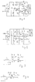
- Fig. 1 of the drawing there is shown the principle diagram of a circuit of the electronic ballast for a fluorescent lamp.
- a wave filter comprising capacitor C1 and choke L0 is connected to the low-voltage mains.
- the output of the wave filter circuit is connected to the input of a rectifier circuit composed of diodes D1-D4.
- the output of the rectifier circuit is connected to the input of a generation and control circuit of high frequency comprising two transistors V1, V2, resistors R2, R3, R4, R5, capacitors C4, C5, diode D5, and feedback transformer B1.
- a filtering capacitor C2 Connected to the output of the rectifier circuit is a filtering capacitor C2.
- Resistor R1 and capacitor C3 are connected in series to the output of the rectifier circuit.
- the collector of transistor V1 is connected to the positive output of the rectifier circuit.
- the emitter of transistor V2 is connected to the negative output of the rectifier circuit.
- the emitter of transistor V1 is connected to the collector of transistor V2.
- Connected to the joint point of emitter of transistor V1 and collector of transistor V2 is the primary coil B1-1 of feedback transformer B1.
- Secondary coil B1-2 of feedback transformer B1 is connected in series with resistor R 3 which is connected to the base of transistor V1.
- Resistor R4 is connected to the base of transistor V2 and the secondary coil B1-3 of feedback transformer B1.
- One end of the secondary coil B1-3 is connected to the negative output of the rectifier circuit.
- One end of secondary coil B1-2 is connected to the joint point of emitter of transistor V1 and collector of transistor V2.
- the second end of capacitor C5 is connected to one tap or contact respectively of the lamp F.
- the other plug-in pin or contact of the lamp F is connected to one end of a choke L and one end of a capacitor C7 which is connected with its other end to the negative output of the rectifier circuit.
- One end of the choke L is connected to the primary coil B1-1 of feedback transformer B1.
- the starting circuit of the fluorescent lamp F includes a capacitor C3 in series with resistor R1 and DIAC DB 3.
- capacitor C7 and choke L form a resonant circuit. Because the capacity of C2 and C5 is relatively big, the voltage of high frequency on C7 is mainly supplied to the two ends of the lamp tube so that the lamp tube can work normally. There are great defects in this circuit if the lamp tube is a part that can be changed. Firstly, the resonance circuit C7 and L will work under the idle situation and the transistor will be burnt out quickly if the plug-in pins of the lamp tube have a loose contact and the lamp tube itself does not work normally. Secondly, the safety regulation requirements of the changeable lamp tube cannot be fulfilled.
- An electronic ballast for a fluorescent lamp with low-voltage power supply comprises a wave filter connected with its output to the input of a rectifier circuit, which is connected with its output to the input of a generation and control circuit of high frequency, the output end of which is connected to the resonance circuit composed of a choke and a capacitor, and an ignition circuit, the generation and control circuit including two solid state switches and feedback transformer means which is put with its primary circuits into the output of the generation and control circuit; at least one coil of the primary circuit of the feedback transformer means for supplying feedback to one of the solid state switches is connected between the joint of the choke and the capacitor of the resonance circuit and one contact of the fluorescent lamp.
- the feedback transformer means comprises two transformers and the primary feedback coil is connected on the two transformers between the joint of the choke and the capacitor of said resonance circuit and said one contact of the fluorescent lamp.
- the feedback transformer means comprises one primary feedback coil connected with a two holes transformer.
- the primary feedback means comprises two transformers; one transformer being connected in the front and one at the back of the choke.
- the primary feedback transformer means comprises one transformer including two primary feedback coils one coil being connected in the front and one coil being connected to the back of the choke.
- the ballast comprises a wave filter circuit composed of choke L0 and capacitor C1, a bridge rectifier circuit composed of bridge stacks D1-D4, a generation and control circuit of high frequency, an ignition circuit for the lamp tube and a resonance circuit.
- the generation and control circuit comprises transistors V1, V2 and their supplementary components for instance resistors R2, R3 and R4, and feedback transformer B1.
- the ignition circuit of the lamp tube is composed for instance of DIAC DB 3, capacitor C3 and resistor R1.
- references L0, C1, C2, C3, C4, C5, C6, C7, R1, R2, R3, R4, R5, D1-D4, D5, DB3, V1, V2, F, and L identify like elements of the circuit in Fig.1.
- the feedback transformer B1 has a primary feedback coil B1-1 which is connected in parallel with the resistor R5, the choke L of the resonance circuit is put in the output of the generation and control circuit by connecting over end to the joint of the emitter of transistor V1 and collector of transistor V2.
- the other end of choke L is connected to one end of capacitor C7 and one end to the primary feedback coil B1-1.
- the other end of the feedback coil B1-1 is connected to one contactor cap of the fluorescent lamp tube F.
- the feedback transformer B1 may comprise two magnet cores M1, M2 as shown in Fig. 2.
- the primary feedback circuit of transformer B1 is divided in two coils B1-1.
- Each core M1, M2 is provided with one half of the primary feedback coil B1-1.
- Each core M1, M2 is provided with a secondary coil B1-2 or B1-3 of the feedback transformer B1.
- the feedback transformer B1 may comprise two a two holes transformer M3.
- the primary feedback coil B1-1 according to Fig. 3 and 4 is connected to the choke L and the lamp tube as shown in Fig. 2.
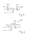
- Fig. 5 shows another embodiment of the present invention.
- the primary feedback circuit of transformer B1 has two magnetic cores M1, M2 with primary feedback coils B1-1, B1-1.
- One coil B1-1 which is on core M1 is connected in the front and one coil B1-1 which is on core M2 is connected at the back choke L.
- the coil B1 in the front of the choke is connected with one end to the joint collector of transistor V2 and the emitter of transistor V1.
- the coil B1-1 at the back of choke L is connected with one end to the lamp tube F.
- the feedback transformer B1 is provided with one core M4.
- the primary feedback circuit is divided up in coils B1-1 and B1-4.
- Coil B1-4 is connected in the front of choke L and coil B1-1 at the back of choke L. If the lamp tube has a loose contact or if there is no lamp in the lampholder, at least one solid state switch will receive no feedback. This switch will be non-conductive. Therefore the electronic ballast stops working.
Landscapes
- Circuit Arrangements For Discharge Lamps (AREA)
Priority Applications (2)
| Application Number | Priority Date | Filing Date | Title |
|---|---|---|---|
| EP99123725A EP1104980A1 (fr) | 1999-11-30 | 1999-11-30 | Ballast électronique pour lampe à décharge |
| US09/725,237 US6351082B1 (en) | 1999-11-30 | 2000-11-29 | Electronic ballast for a fluorescent lamp |
Applications Claiming Priority (1)
| Application Number | Priority Date | Filing Date | Title |
|---|---|---|---|
| EP99123725A EP1104980A1 (fr) | 1999-11-30 | 1999-11-30 | Ballast électronique pour lampe à décharge |
Publications (1)
| Publication Number | Publication Date |
|---|---|
| EP1104980A1 true EP1104980A1 (fr) | 2001-06-06 |
Family
ID=8239491
Family Applications (1)
| Application Number | Title | Priority Date | Filing Date |
|---|---|---|---|
| EP99123725A Withdrawn EP1104980A1 (fr) | 1999-11-30 | 1999-11-30 | Ballast électronique pour lampe à décharge |
Country Status (2)
| Country | Link |
|---|---|
| US (1) | US6351082B1 (fr) |
| EP (1) | EP1104980A1 (fr) |
Families Citing this family (2)
| Publication number | Priority date | Publication date | Assignee | Title |
|---|---|---|---|---|
| KR200439972Y1 (ko) * | 2007-12-18 | 2008-05-19 | 조헌구 | 방전등 냉각장치 |
| CN102573178A (zh) * | 2010-12-15 | 2012-07-11 | 成都蜀昌科技有限公司 | 一种led照明节能灯通用稳压电源 |
Citations (4)
| Publication number | Priority date | Publication date | Assignee | Title |
|---|---|---|---|---|
| EP0099474A1 (fr) * | 1982-07-12 | 1984-02-01 | GTE Products Corporation | Circuit d'attache électronique pour une lampe à décharge |
| US4954754A (en) * | 1988-05-02 | 1990-09-04 | Nilssen Ole K | Controlled electronic ballast |
| US5402043A (en) * | 1978-03-20 | 1995-03-28 | Nilssen; Ole K. | Controlled driven series-resonant ballast |
| US5512801A (en) * | 1980-08-14 | 1996-04-30 | Nilssen; Ole K. | Ballast for instant-start parallel-connected lamps |
Family Cites Families (4)
| Publication number | Priority date | Publication date | Assignee | Title |
|---|---|---|---|---|
| DE3829388A1 (de) * | 1988-08-30 | 1990-03-01 | Patent Treuhand Ges Fuer Elektrische Gluehlampen Mbh | Schaltungsanordnung zum betrieb einer last |
| DE4430397A1 (de) * | 1994-08-26 | 1996-02-29 | Patent Treuhand Ges Fuer Elektrische Gluehlampen Mbh | Schaltungsanordnung zum Betrieb von Niederdruckentladungslampen |
| US5898278A (en) * | 1995-08-09 | 1999-04-27 | Pinbeam Ag | Series resonant lamp circuit having direct electrode connection between rectifier and AC source |
| DE19548506A1 (de) * | 1995-12-22 | 1997-06-26 | Patent Treuhand Ges Fuer Elektrische Gluehlampen Mbh | Schaltungsanordnung zum Betrieb einer Lampe |
-
1999
- 1999-11-30 EP EP99123725A patent/EP1104980A1/fr not_active Withdrawn
-
2000
- 2000-11-29 US US09/725,237 patent/US6351082B1/en not_active Expired - Fee Related
Patent Citations (4)
| Publication number | Priority date | Publication date | Assignee | Title |
|---|---|---|---|---|
| US5402043A (en) * | 1978-03-20 | 1995-03-28 | Nilssen; Ole K. | Controlled driven series-resonant ballast |
| US5512801A (en) * | 1980-08-14 | 1996-04-30 | Nilssen; Ole K. | Ballast for instant-start parallel-connected lamps |
| EP0099474A1 (fr) * | 1982-07-12 | 1984-02-01 | GTE Products Corporation | Circuit d'attache électronique pour une lampe à décharge |
| US4954754A (en) * | 1988-05-02 | 1990-09-04 | Nilssen Ole K | Controlled electronic ballast |
Also Published As
| Publication number | Publication date |
|---|---|
| US6351082B1 (en) | 2002-02-26 |
Similar Documents
| Publication | Publication Date | Title |
|---|---|---|
| US4507698A (en) | Inverter-type ballast with ground-fault protection | |
| EP0239793B1 (fr) | Disposition de circuit pour la mise en oeuvre de lampes à décharge basse pression | |
| US6459213B1 (en) | Ballast for parallel-connected lamps | |
| US6069455A (en) | Ballast having a selectively resonant circuit | |
| JPS6329496A (ja) | 低圧放電灯作動用回路装置 | |
| EP0802702A3 (fr) | Approvisionnement d'énergie par lampe fluorescente à cathode froid de haute efficacité | |
| US4506195A (en) | Apparatus for operating HID lamp at high frequency with high power factor and for providing standby lighting | |
| US5185560A (en) | Electronic fluorescent lamp ballast | |
| EP0440244A2 (fr) | Appareil pour alimenter une lampe À décharge | |
| US5214355A (en) | Instant-start electronic ballast | |
| US6211625B1 (en) | Electronic ballast with over-voltage protection | |
| DE4032664A1 (de) | Schaltungsanordnung zum betrieb von niederdruckentladungslampen | |
| EP0294605A2 (fr) | Dispositif de circuit pour mettre en oeuvre une lampe à décharge branchée à une source basse tension | |
| EP2015617A2 (fr) | Ballasts électroniques sans noyau magnétique toroïdal et lampes fluorescentes les utilisant | |
| DE3632272A1 (de) | Elektronische schaltungsanordnung zum betreiben von niederdruckentladungslampen in reihenschaltung | |
| US6351082B1 (en) | Electronic ballast for a fluorescent lamp | |
| EP0697803B1 (fr) | Circuit pour alimenter des lampes à décharge | |
| EP0294604A1 (fr) | Circuit pour le fonctionnement d'une lampe à décharge à partir d'une source de tension continue à bas voltage | |
| EP0648068B1 (fr) | Circuit d'alimentation de lampes électriques | |
| US4701673A (en) | Ballast adaptor for improving operation of fluorescent lamps | |
| US6198228B1 (en) | Plug-in fluorescent lighting system | |
| CN2256203Y (zh) | 一种新型电压源谐振式电子镇流器 | |
| CN2475253Y (zh) | 谐振式电感型荧光灯镇流器 | |
| JPH048915B2 (fr) | ||
| KR900002177Y1 (ko) | 다등식 방전등용 안정기 점등회로 |
Legal Events
| Date | Code | Title | Description |
|---|---|---|---|
| PUAI | Public reference made under article 153(3) epc to a published international application that has entered the european phase |
Free format text: ORIGINAL CODE: 0009012 |
|
| AK | Designated contracting states |
Kind code of ref document: A1 Designated state(s): DE FR GB IT NL SE |
|
| AX | Request for extension of the european patent |
Free format text: AL;LT;LV;MK;RO;SI |
|
| 17P | Request for examination filed |
Effective date: 20010907 |
|
| AKX | Designation fees paid |
Free format text: DE FR GB IT NL SE |
|
| STAA | Information on the status of an ep patent application or granted ep patent |
Free format text: STATUS: THE APPLICATION HAS BEEN WITHDRAWN |
|
| 18W | Application withdrawn |
Effective date: 20021112 |