EP1105207B1 - Vorrichtung zur präzisen abgabe geringer mengen ultra-feiner partikel - Google Patents
Vorrichtung zur präzisen abgabe geringer mengen ultra-feiner partikel Download PDFInfo
- Publication number
- EP1105207B1 EP1105207B1 EP99938091A EP99938091A EP1105207B1 EP 1105207 B1 EP1105207 B1 EP 1105207B1 EP 99938091 A EP99938091 A EP 99938091A EP 99938091 A EP99938091 A EP 99938091A EP 1105207 B1 EP1105207 B1 EP 1105207B1
- Authority
- EP
- European Patent Office
- Prior art keywords
- stage
- stage chamber
- particles
- chamber
- recited
- Prior art date
- Legal status (The legal status is an assumption and is not a legal conclusion. Google has not performed a legal analysis and makes no representation as to the accuracy of the status listed.)
- Expired - Lifetime
Links
Images

Classifications
-
- B—PERFORMING OPERATIONS; TRANSPORTING
- B01—PHYSICAL OR CHEMICAL PROCESSES OR APPARATUS IN GENERAL
- B01F—MIXING, e.g. DISSOLVING, EMULSIFYING OR DISPERSING
- B01F23/00—Mixing according to the phases to be mixed, e.g. dispersing or emulsifying
- B01F23/30—Mixing gases with solids
-
- B—PERFORMING OPERATIONS; TRANSPORTING
- B01—PHYSICAL OR CHEMICAL PROCESSES OR APPARATUS IN GENERAL
- B01F—MIXING, e.g. DISSOLVING, EMULSIFYING OR DISPERSING
- B01F25/00—Flow mixers; Mixers for falling materials, e.g. solid particles
- B01F25/30—Injector mixers
- B01F25/31—Injector mixers in conduits or tubes through which the main component flows
- B01F25/312—Injector mixers in conduits or tubes through which the main component flows with Venturi elements; Details thereof
- B01F25/3121—Injector mixers in conduits or tubes through which the main component flows with Venturi elements; Details thereof with additional mixing means other than injector mixers, e.g. screens, baffles or rotating elements
-
- B—PERFORMING OPERATIONS; TRANSPORTING
- B01—PHYSICAL OR CHEMICAL PROCESSES OR APPARATUS IN GENERAL
- B01F—MIXING, e.g. DISSOLVING, EMULSIFYING OR DISPERSING
- B01F25/00—Flow mixers; Mixers for falling materials, e.g. solid particles
- B01F25/30—Injector mixers
- B01F25/31—Injector mixers in conduits or tubes through which the main component flows
- B01F25/312—Injector mixers in conduits or tubes through which the main component flows with Venturi elements; Details thereof
- B01F25/3124—Injector mixers in conduits or tubes through which the main component flows with Venturi elements; Details thereof characterised by the place of introduction of the main flow
- B01F25/31242—Injector mixers in conduits or tubes through which the main component flows with Venturi elements; Details thereof characterised by the place of introduction of the main flow the main flow being injected in the central area of the venturi, creating an aspiration in the circumferential part of the conduit
-
- B—PERFORMING OPERATIONS; TRANSPORTING
- B01—PHYSICAL OR CHEMICAL PROCESSES OR APPARATUS IN GENERAL
- B01F—MIXING, e.g. DISSOLVING, EMULSIFYING OR DISPERSING
- B01F33/00—Other mixers; Mixing plants; Combinations of mixers
- B01F33/40—Mixers using gas or liquid agitation, e.g. with air supply tubes
- B01F33/402—Mixers using gas or liquid agitation, e.g. with air supply tubes comprising supplementary stirring elements
-
- B—PERFORMING OPERATIONS; TRANSPORTING
- B01—PHYSICAL OR CHEMICAL PROCESSES OR APPARATUS IN GENERAL
- B01F—MIXING, e.g. DISSOLVING, EMULSIFYING OR DISPERSING
- B01F2101/00—Mixing characterised by the nature of the mixed materials or by the application field
- B01F2101/2202—Mixing compositions or mixers in the medical or veterinary field
Definitions
- This invention relates to the accurate dispensing of very small quantities of ultra-fine particles in a reproducible manner.
- the inventors are not aware of any available technology to dispense such small quantities of ultra-fine particles on a dry basis.
- several types of solids feeding systems have been developed over the years. Among them are feeders designed to deliver particles at flowrates of the order of 1 kg/h for laboratory and pilot scale gas-solid reactions (e.g. combustion, gasification, catalytic reactions and metallurgical processes).
- the most common kind of solids feeder is a mechanical feeder such as a belt or screw conveyor.
- mechanical feeders are generally inefficient and unreliable in feeding very fine particles in particular, due to the cohesive properties of the powder which prevent free motion of solids and lead to difficulty in transporting the powder.
- a fluidized bed feeder as a non-mechanical solids feeder would have the potential to dispense smaller quantities with suitable reproducibility. While there are several types of conventional fluidized bed feeders developed, none of them is suitable for the required small quantities and ultra-fine particles. None of the prior art feeders known to the inventors can dispense the very small quantity of fine particles of interest here.
- the first stage is preferably a fluidized bed with a freeboard on the top, but possibly a dilute-phase fluidized bed with a dilute gas-solids suspension filling the whole chamber, and the second stage is a dilute gas-solid suspension fluidized bed.
- the second stage receives particles drawn from suspended particles in the first stage, and produces a very uniform dilute suspension of those particles, from which very accurate quantities can then be drawn.
- the invention has first-stage and second-stage gas-solids suspension or fluidization chambers, each having particle fluidization means, and a conduit connecting the first-stage and second-stage chambers, for flow of suspended particles from the first-stage chamber to the second-stage chamber.
- a pressure differential is created between the first-stage and second-stage chambers, by means such as a Venturi for example, to transfer suspended particles from the first-stage chamber into the second-stage chamber via the conduit.
- suspended particles are drawn from the second-stage chamber via withdrawal ports, into a collection area for dispensing therefrom.
- multiple second-stage chambers can be provided, each drawing suspended particles via a separate conduit from the first-stage chamber, which is potentially much larger.
- first-stage chamber there could be a quite large first-stage chamber, with conduits extending to many second-stage chambers at remote locations.
- One advantage of this invention is that accurate dispensing of small quantities of fine particles is achieved using cost-effective pneumatic rather than mechanical means.
- the invention is well-suited for ultra-fine particles and for small quantities, the invention can also handle larger particles and quantities of larger than 1 mg, up to the point where other more conventional methods begin to work more effectively, for example in the 100-200 mg range.
- the application of the invention is, therefore, not to be construed as one that is strictly limited to dispensing only very small quantities of the order of 1 mg or less, and ultra-fine particles, although that is where the invention is potentially most useful.
- first-stage chamber stage in the preferred embodiment of the invention is a dense-phase fluidized bed with a freeboard on the top, it should be appreciated that the first stage could instead also be a dilute-phase fluidized bed with a dilute gas-solids suspension filling the whole chamber.
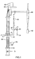
- Fig. 1 illustrates the preferred embodiment of the system.
- a first-stage gas-solids fluidization chamber 20 in which loaded particles are fluidized by any suitable conventional means to form a suspension of particles, for example via a fluidizing gas G introduced through a windbox 50 and a perforated-plate air distributor 51 clamped between two flanges.
- fluidization aids may be used, such as six impellers 60 positioned within the fluidization bed to stir the dense phase in order to improve the fluidization quality of the very fine particles, the impellers being mounted onto a shaft 64 driven by a mechanical stirrer 62 .
- a vibrator 70 of variable frequency such as a pneumatic turbine, may also be mounted on the outer wall of the main column to aid in fluidizing the fine cohesive particles.
- Other fluidization aids could also be employed as required or desired, including the "Gaseous Fluidization Aids" described in co-pending international patent application no. PCT/CA99/ of that title, filed August 13, 1999, claiming priority from U.S. patent application ser. no. 09/133,215, these applications being hereby incorporated by reference.
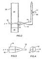
- a conduit 15 connects a freeboard area 41 (i.e. the area above the bed of powders 40 where there is a suspension of particles - see Fig. 2) of the first-stage chamber 20 to a second-stage gas-solids fluidization chamber 30 for flow of suspended particles from the first-stage to the second-stage chamber.
- a pressure differential is created between the first-stage and second-stage chambers, by means such as a Venturi 10 in the conduit 15 for example, fed by a high speed gas stream J (having a velocity in the order of 10 - 50 m/s, for example) introduced via a gas feed tube 16 to produce the desired Venturi effect and thus the desired flow of suspended particles from the first-stage chamber into the second-stage chamber.
- This two-stage fluidization results in extremely accurate dispensing, since a dilute, very stable and very uniform suspension is achieved in the second-stage chamber. Accurate, reliable and reproducible quantities are obtained, such that in production, once operating conditions are set and calibrated, only periodic checking of collected amounts for purposes of quality control monitoring should be required.
- multiple "second” chambers 30 can be provided, each drawing suspended particles via a separate conduit 15 from the first-stage chamber, which is potentially much larger.
- this description focuses on the situation where there is only a single second-stage chamber, but it should be clearly understood that multiple second-stage chambers are also contemplated.
- the separate conduits 15 would draw from different points around the circumference of the first-stage chamber, at the same height or at different heights as desired.
- each second-stage chamber 30 could have multiple withdrawal tubes 31 . Again for clarity of illustration and explanation, this description focuses on the situation where there is only a single withdrawal tube.
- any form of conduit in which a pressure difference between the first-stage fluidization chamber and the second-stage fluidization chamber is provided, so as to result in lower pressure in the second-stage chamber and hence flow from the first-stage chamber to the second-stage chamber, would be suitable in this invention.
- a vacuum (not shown) could be disposed in the general area at the upper end of the second-stage fluidization chamber 30 , to provide a lower pressure in the conduit.
- the first-stage fluidization chamber may be pressurized to a pressure greater than the second-stage fluidization chamber or chambers.
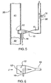
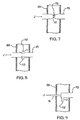
- Figs. 3-9 show examples of alternative configurations which can be used with a Venturi to draw suspended particles from the first-stage chamber 20.
- Figs. 3 and 4 show the conduit 15 having an end plate 14 which has several orifices 12 therethrough to draw particles from the first-stage chamber. The plate acts to control the mass flow rate of particles diverted to the second-stage chamber.
- a central opening 13 is also provided, to accommodate the high speed gas feed tube 16 . This is essentially the configuration also shown in Figs. 1 and 2 in less detail.
- the orifices 12 are drilled into the wall of the conduit 15 where it extends slightly into the first-stage chamber 20 .
- the first embodiment is advantageous in that a variety of orifice numbers and sizes may be used without changing the Venturi apparatus.
- Fig. 7 illustrates a setup in which Venturi 10 neck is positioned within the first-stage chamber 20 , with the orifices 12 being at the neck.
- Fig. 8 shows tubes 11 intersecting the conduit 15 in the first-stage chamber 20 , the resulting reduced cross-sectional area thus creating a Venturi effect.
- the tubes 11 draw the suspended particles into the conduit, the outer ends of the tubes acting as the orifices 12 .
- Fig. 9 shows a similar arrangement to that of Fig. 8.
- the orifices 12 are about 1-5 mm in diameter.
- the Venturi is positioned at a high location in the freeboard. It should be understood that a variety of positions may be suitable for the Venturi, as long as the conduit will draw diluted particles from the freeboard of the dense particle bed in the first-stage chamber. However, in some cases when larger quantities are being metered, it may be necessary to have the conduit draw from or close to the dense bed to increase the flow rate.
- a high efficiency cyclone 80 is preferably installed at the exit of the first-stage chamber 20, to capture particles carried out by the fluidizing gas stream F (i.e. from G), so that they are not lost.
- the captured particles are collected in a container 82, and if desired, may be reintroduced to the bottom of the particle bed in the bottom of the first-stage chamber. If preferred, the cyclone or any suitable form of particle filtering system instead could be placed within the freeboard.
- the dilute gas-particle fluidization flow from the second-stage chamber 30 is not returned to the main fluidization column, i.e. the first-stage chamber 20 , to ensure that there is enough pressure drop between the inside of the Venturi and the freeboard of the dense fluidized bed and to thereby to provide smooth flow of particles from the main fluidized bed column into the Venturi.
- the gas-particle suspension preferably is passed through a filter (not shown) to catch the fine powder while the air is released to the atmosphere. This flow of the gas-particle suspension is illustrated by the arrow marked F'.
- the separated particles would likely be returned to the first-stage chamber.
- a butterfly valve 32 is installed at the exit of the second-stage chamber.
- This valve is normally open during the operation of the system, but could be closed periodically and a source of air could be introduced into the column to force the air to flow back into the dense bed periodically so as to purge the Venturi, to prevent the orifices 12 from becoming blocked by the fine particles.
- the two gas streams ( G and J ) may be, preferably, first passed through two separate packed bed adsorption tubes containing a desiccant such as silica gel.
- FIG. 10 A schematic of the preferred particle withdrawal system is shown in Fig. 10.
- the withdrawal of particles is controlled by a three-way solenoid valve 33 and a timer (not shown).
- Line A and the withdrawal tube 31 are initially open while line C is closed by the solenoid valve, so that back-purging gas from line A flows into the dilute fluidization column, preventing the particles from entering the withdrawal tube 31.
- line C is opened and line A is closed by the three-way solenoid valve 33.
- the gas-solids suspension begins to flow out of the dilute bed 30 into the withdrawal tube 31 and thence into the collection cell 34.
- This flow is caused by the small pressure difference between the dilute fluidization column and the outside, and can be enhanced by applying a suction pressure (vacuum) at the end of the withdrawal train.
- a suction pressure vacuum
- a predetermined amount of particles is dispensed simply by controlling the amount of time the solenoid is open. As mentioned above, this can be readily controlled and calibrated to produce a highly accurate, reliable and reproducible quantity.
- An alternative withdrawal apparatus would be a two-way solenoid valve installed in a single-tube line connecting the dilute phase column and the collection cell.
- the solenoid valve would be closed when there is no withdrawal and open during the withdrawal process. Purging would become unnecessary when the withdrawal frequency is very high.
- the invention provides improved dispensing of powders.
Landscapes
- Chemical & Material Sciences (AREA)
- Chemical Kinetics & Catalysis (AREA)
- Devices And Processes Conducted In The Presence Of Fluids And Solid Particles (AREA)
Claims (13)
- Vorrichtung zur Abgabe von trockenen Partikeln, die Folgendes umfasst:eine Gas-Feststoff-Wirbelkammer einer ersten Stufe und mindestens eine Gas-Feststoff-Wirbelkammer einer zweiten Stufe, wobei die Kammern der ersten und der zweiten Stufe Partikelfluidisierungsmittel zur Erzeugung einer Suspension der Partikel in den Kammern aufweisen;für jede Kammer der zweiten Stufe eine Leitung, die so angeschlossen ist, dass Partikel von der Kammer der ersten Stufe zur Kammer der zweiten Stufe zwecks Suspension in der Kammer der zweiten Stufe strömen;ein Mittel zur Bereitstellung eines Druckabfalls von der Kammer der ersten Stufe zu jeder Kammer der zweiten Stufe zur Erzeugung des Partikelstroms von der Kammer der ersten Stufe zur Kammer der zweiten Stufe; undfür jede Kammer der zweiten Stufe ein Mittel zum Abziehen suspendierter Partikel aus der Kammer der zweiten Stufe in mindestens einen Sammelbereich.
- Vorrichtung nach Anspruch 1, bei der die Leitung so angeschlossen ist, dass von der Kammer der ersten Stufe zur Kammer der zweiten Stufe strömende Partikel in der Kammer der ersten Stufe suspendierte Partikel sind.
- Vorrichtung nach Anspruch 1, bei der mehr als eine Kammer der zweiten Stufe vorhanden ist.
- Vorrichtung nach Anspruch 1, bei der mehrere solche Mittel zum Abziehen suspendierter Partikel aus jeder der Kammern der zweiten Stufe in mehrere entsprechende Sammelbereiche vorhanden sind.
- Vorrichtung nach Anspruch 1, bei der das Mittel zum Abziehen suspendierter Partikel aus der Kammer (30) der zweiten Stufe in einen Sammelbereich ein Dreiwegeventil (33) mit drei Anschlüssen umfasst, nämlich einem zu einem mit der Kammer (30) der zweiten Stufe verbundenen Abziehrohr (31), einem zu einer Spülgasversorgung und einem zu einer Sammelzelle (34), wobei das Ventil (33) dahingehend betätigbar ist, dass in einer Stellung Spülgas in die Kammer (30) der zweiten Stufe strömt und verhindert wird, dass Partikel in das Abziehrohr (31) eindringen, während in einer anderen Stellung ein Spülgasstrom verhindert wird und Partikel durch das Abziehrohr (31) und in die Sammelzelle (34) strömen können, wodurch durch Steuerung der Zeitdauer, während der sich das Ventil (33) in der anderen Stellung befindet, eine vorbestimmte Partikelmenge abgegeben werden kann.
- Vorrichtung nach Anspruch 1, bei der die Kammer der zweiten Stufe eine Dünnphasen-Wirbelschicht mit einer die ganze Kammer füllenden verdünnten Gas-Feststoff-Suspension aufweist.
- Vorrichtung nach Anspruch 6, bei der die Kammer der ersten Stufe eine Dichtphasen-Wirbelschicht mit einem Freiraum über der Schicht aufweist.
- Vorrichtung nach Anspruch 6, bei der die Kammer der ersten Stufe eine Dünnphasen-Wirbelschicht mit einer die ganze Kammer füllenden verdünnten Gas-Feststoff-Suspension aufweist.
- Vorrichtung nach Anspruch 1, bei der das Mittel zur Bereitstellung eines Druckabfalls von der Kammer der ersten Stufe zu jeder Kammer der zweiten Stufe ein Venturi-Rohr in jeder Leitung ist, das zur Erzeugung einer Venturi-Wirkung mit einem Hochgeschwindigkeitsgas versorgt wird.
- Vorrichtung nach Anspruch 1, bei der das Mittel zur Bereitstellung eines Druckabfalls von der Kammer der ersten Stufe zu jeder Kammer der zweiten Stufe durch Druckbeaufschlagung der Kammer der ersten Stufe über eine Druckhöhe jeder Kammer der zweiten Stufe erfolgt.
- Vorrichtung nach Anspruch 1, bei der das Mittel zum Abziehen suspendierter Partikel aus der Kammer der zweiten Stufe in mindestens einen Sammelbereich für jeden Sammelbereich eine zwischen der Kammer der zweiten Stufe und dem Sammelbereich angeschlossene Abziehleitung mit einem Druckabfall von der Kammer der zweiten Stufe zum Sammelbereich und mit einem Ventil zwischen jeder Abziehleitung und jedem Sammelbereich, so dass der Partikelstrom von der Kammer der zweiten Stufe zum Sammelbereich durch das Ventil gesteuert wird, umfasst.
- Vorrichtung nach Anspruch 11, bei der es sich bei dem Ventil um ein zeitgesteuertes Magnetventil handelt.
- Vorrichtung nach Anspruch 12, bei der das Magnetventil ein Dreiwegeventil ist, dessen drei Kanäle mit der Abziehleitung, dem Sammelbereich bzw. einer Versorgung für Spülgas höheren Drucks verbunden sind, so dass das Spülgas in der Abziehleitung zur Kammer der zweiten Stufe zurückströmen kann, wodurch verhindert wird, dass suspendierte Partikel in das Abziehrohr eindringen, bis das Dreiwegeventil zur Verbindung des Abziehrohrs mit dem Sammelbereich statt mit der Spülgasversorgung betätigt wird.
Applications Claiming Priority (3)
| Application Number | Priority Date | Filing Date | Title |
|---|---|---|---|
| US133216 | 1998-08-13 | ||
| US09/133,216 US6183169B1 (en) | 1998-08-13 | 1998-08-13 | Precision dispensing of ultra-fines via a gas medium |
| PCT/CA1999/000743 WO2000009249A1 (en) | 1998-08-13 | 1999-08-13 | Apparatus for precisely dispensing small amounts of ultra-fine particles |
Publications (2)
| Publication Number | Publication Date |
|---|---|
| EP1105207A1 EP1105207A1 (de) | 2001-06-13 |
| EP1105207B1 true EP1105207B1 (de) | 2003-01-02 |
Family
ID=22457522
Family Applications (1)
| Application Number | Title | Priority Date | Filing Date |
|---|---|---|---|
| EP99938091A Expired - Lifetime EP1105207B1 (de) | 1998-08-13 | 1999-08-13 | Vorrichtung zur präzisen abgabe geringer mengen ultra-feiner partikel |
Country Status (7)
| Country | Link |
|---|---|
| US (1) | US6183169B1 (de) |
| EP (1) | EP1105207B1 (de) |
| CN (1) | CN1103242C (de) |
| AU (1) | AU761258B2 (de) |
| CA (1) | CA2340171A1 (de) |
| DE (1) | DE69904728D1 (de) |
| WO (1) | WO2000009249A1 (de) |
Families Citing this family (9)
| Publication number | Priority date | Publication date | Assignee | Title |
|---|---|---|---|---|
| JP2000344343A (ja) * | 1999-06-01 | 2000-12-12 | Mitsui High Tec Inc | 球状物の搬送装置および搬送方法 |
| EP1390699B1 (de) | 2001-04-20 | 2007-10-17 | Glaxo Group Limited | Messmethode für teilchenmaterial |
| US6684917B2 (en) | 2001-12-17 | 2004-02-03 | The University Of Western Ontario | Apparatus for volumetric metering of small quantity of powder from fluidized beds |
| US6688494B2 (en) * | 2001-12-20 | 2004-02-10 | Cima Nanotech, Inc. | Process for the manufacture of metal nanoparticle |
| US7662217B2 (en) * | 2007-04-03 | 2010-02-16 | Battelle Energy Alliance, Llc | Soil separator and sampler and method of sampling |
| US7582265B2 (en) * | 2007-06-28 | 2009-09-01 | Plasma Waste Recycling, Inc. | Gas conduit for plasma gasification reactors |
| WO2013032801A1 (en) * | 2011-09-02 | 2013-03-07 | First Solar, Inc. | Feeder system and method for a vapor transport deposition system |
| TWI581863B (zh) * | 2015-07-28 | 2017-05-11 | 勞動部勞動及職業安全衛生研究所 | 粉體分散器及其系統 |
| CN108215299B (zh) * | 2017-11-24 | 2024-01-19 | 卓弢机器人盐城有限公司 | 一种环保粉料自动压片和下料装置 |
Family Cites Families (11)
| Publication number | Priority date | Publication date | Assignee | Title |
|---|---|---|---|---|
| US2715551A (en) * | 1952-12-09 | 1955-08-16 | Air Reduction | Apparatus for dispensing powdered materials at superatmospheric pressure |
| US4367685A (en) * | 1980-09-08 | 1983-01-11 | Frame Scott W | Process and apparatus for precisely metering quantities of granular or pulverulent solids |
| GB2130906B (en) * | 1982-11-19 | 1986-06-04 | Robert Francis Boucher | Improvements in or relating to apparatus for dispensing a dust suspension |
| DE3309210A1 (de) * | 1983-03-15 | 1984-09-20 | Krupp Polysius Ag, 4720 Beckum | Verfahren und vorrichtung zur pneumatischen foerderung von feingut |
| US4824295A (en) * | 1984-12-13 | 1989-04-25 | Nordson Corporation | Powder delivery system |
| JPS63283728A (ja) * | 1987-05-14 | 1988-11-21 | Chuo Kakoki Kk | 粉体の分散混合装置 |
| DK479189D0 (da) * | 1989-01-06 | 1989-09-28 | Hans Gernot Schenk | Inhalator |
| WO1993025193A1 (fr) * | 1992-06-12 | 1993-12-23 | Teijin Limited | Preparation pharmaceutique destinee a etre administree par les voies respiratoires |
| EP0611567B1 (de) * | 1992-06-12 | 2002-08-28 | Teijin Limited | Ultrafeines pulver zur inhalation und dessen herstellung |
| US5494520A (en) * | 1994-10-07 | 1996-02-27 | Xerox Corporation | Apparatus for coating jet milled particulates onto a substrate by use of a rotatable applicator |
| AU706195B2 (en) * | 1995-04-14 | 1999-06-10 | Inhale Therapeutic Systems | Powdered pharmaceutical formulations having improved dispersibility |
-
1998
- 1998-08-13 US US09/133,216 patent/US6183169B1/en not_active Expired - Fee Related
-
1999
- 1999-08-13 EP EP99938091A patent/EP1105207B1/de not_active Expired - Lifetime
- 1999-08-13 CA CA002340171A patent/CA2340171A1/en not_active Abandoned
- 1999-08-13 DE DE69904728T patent/DE69904728D1/de not_active Expired - Lifetime
- 1999-08-13 AU AU52737/99A patent/AU761258B2/en not_active Ceased
- 1999-08-13 CN CN99810716A patent/CN1103242C/zh not_active Expired - Fee Related
- 1999-08-13 WO PCT/CA1999/000743 patent/WO2000009249A1/en not_active Ceased
Also Published As
| Publication number | Publication date |
|---|---|
| CA2340171A1 (en) | 2000-02-24 |
| DE69904728D1 (de) | 2003-02-06 |
| AU761258B2 (en) | 2003-05-29 |
| CN1103242C (zh) | 2003-03-19 |
| EP1105207A1 (de) | 2001-06-13 |
| AU5273799A (en) | 2000-03-06 |
| US6183169B1 (en) | 2001-02-06 |
| CN1316916A (zh) | 2001-10-10 |
| WO2000009249A1 (en) | 2000-02-24 |
Similar Documents
| Publication | Publication Date | Title |
|---|---|---|
| US6684917B2 (en) | Apparatus for volumetric metering of small quantity of powder from fluidized beds | |
| US5556238A (en) | Process and apparatus for introducing a solid into a reactor | |
| US4183702A (en) | Storage and extraction device for powdered products | |
| US3870375A (en) | Powder spray system | |
| EP1105207A1 (de) | Vorrichtung zur präzisen abgabe geringer mengen ultra-feiner partikel | |
| JP2002503195A (ja) | 固形材料、顆粒材料、もしくは粉末材料を搬送するための方法並びに装置 | |
| US20020033173A1 (en) | Controlled deliveries and depositions of pharmaceutical and other aerosolized masses | |
| CN101820963A (zh) | 产生干燥配制物的系统和方法 | |
| KR20020090241A (ko) | 점착성 벌크 고형 분말을 정확하게 계량하고 운반하기위한 이동가능한 장치 | |
| EP1173263A1 (de) | Verfahren zur sprühtrocknung und eine anlage dafür sowie teilchenförmiges material hergestellt durch das verfahren | |
| US5816509A (en) | Apparatus for continuously supplying fine powder in minute and quantitative amounts | |
| CN101798022B (zh) | 多路出料密相气力输送装置和方法 | |
| CN1197751C (zh) | 固体粉粒体气力输送及掺混装置 | |
| US5360297A (en) | Apparatus for automatic level control in a closed channel or container for transport and/or distribution of fluidizable material | |
| CN109230541B (zh) | 一种微型流化床上吸式粉体物料喂料装置及喂料方法 | |
| EP0140570A1 (de) | Zuführen von körnigem Material | |
| JPH0777604B2 (ja) | 可変圧力下にある容器内に粉体材料の所定量を空気的手段により注入する為の方法および装置 | |
| CN1274568C (zh) | 密相气力输送进料装置和方法 | |
| JPH0640043B2 (ja) | ガス‐固体流によつて流過される管路および/または容器において圧力パルスを取り出す装置 | |
| JPH07163857A (ja) | 流動床からの気体と固体の流れの中に存在する固体を配量供給するための装置及び方法 | |
| CN1043852C (zh) | 对颗粒状或粒状物料进行配料的方法和装置 | |
| CN1535184A (zh) | 包衣的方法和设备 | |
| CN112657436A (zh) | 一种改善流化床密、稀相段压差的装置及应用 | |
| JPH0257249A (ja) | 歯科用グラニユレート材の移動方法及び装置 | |
| EP0236320A1 (de) | Zufuhrvorrichtung für teilchenförmige feststoffe |
Legal Events
| Date | Code | Title | Description |
|---|---|---|---|
| PUAI | Public reference made under article 153(3) epc to a published international application that has entered the european phase |
Free format text: ORIGINAL CODE: 0009012 |
|
| 17P | Request for examination filed |
Effective date: 20010305 |
|
| AK | Designated contracting states |
Kind code of ref document: A1 Designated state(s): AT BE CH CY DE DK ES FI FR GB GR IE IT LI LU MC NL PT SE |
|
| GRAG | Despatch of communication of intention to grant |
Free format text: ORIGINAL CODE: EPIDOS AGRA |
|
| 17Q | First examination report despatched |
Effective date: 20020415 |
|
| GRAG | Despatch of communication of intention to grant |
Free format text: ORIGINAL CODE: EPIDOS AGRA |
|
| GRAG | Despatch of communication of intention to grant |
Free format text: ORIGINAL CODE: EPIDOS AGRA |
|
| GRAH | Despatch of communication of intention to grant a patent |
Free format text: ORIGINAL CODE: EPIDOS IGRA |
|
| GRAH | Despatch of communication of intention to grant a patent |
Free format text: ORIGINAL CODE: EPIDOS IGRA |
|
| GRAA | (expected) grant |
Free format text: ORIGINAL CODE: 0009210 |
|
| AK | Designated contracting states |
Kind code of ref document: B1 Designated state(s): CH DE FR GB IE LI SE |
|
| PG25 | Lapsed in a contracting state [announced via postgrant information from national office to epo] |
Ref country code: LI Free format text: LAPSE BECAUSE OF FAILURE TO SUBMIT A TRANSLATION OF THE DESCRIPTION OR TO PAY THE FEE WITHIN THE PRESCRIBED TIME-LIMIT Effective date: 20030102 Ref country code: FR Free format text: LAPSE BECAUSE OF FAILURE TO SUBMIT A TRANSLATION OF THE DESCRIPTION OR TO PAY THE FEE WITHIN THE PRESCRIBED TIME-LIMIT Effective date: 20030102 Ref country code: CH Free format text: LAPSE BECAUSE OF FAILURE TO SUBMIT A TRANSLATION OF THE DESCRIPTION OR TO PAY THE FEE WITHIN THE PRESCRIBED TIME-LIMIT Effective date: 20030102 |
|
| REG | Reference to a national code |
Ref country code: GB Ref legal event code: FG4D Free format text: 20030102 |
|
| REG | Reference to a national code |
Ref country code: CH Ref legal event code: EP |
|
| REG | Reference to a national code |
Ref country code: IE Ref legal event code: FG4D |
|
| REF | Corresponds to: |
Ref document number: 69904728 Country of ref document: DE Date of ref document: 20030206 Kind code of ref document: P |
|
| PG25 | Lapsed in a contracting state [announced via postgrant information from national office to epo] |
Ref country code: SE Free format text: LAPSE BECAUSE OF FAILURE TO SUBMIT A TRANSLATION OF THE DESCRIPTION OR TO PAY THE FEE WITHIN THE PRESCRIBED TIME-LIMIT Effective date: 20030402 |
|
| PG25 | Lapsed in a contracting state [announced via postgrant information from national office to epo] |
Ref country code: DE Free format text: LAPSE BECAUSE OF FAILURE TO SUBMIT A TRANSLATION OF THE DESCRIPTION OR TO PAY THE FEE WITHIN THE PRESCRIBED TIME-LIMIT Effective date: 20030403 |
|
| REG | Reference to a national code |
Ref country code: CH Ref legal event code: PL |
|
| PG25 | Lapsed in a contracting state [announced via postgrant information from national office to epo] |
Ref country code: IE Free format text: LAPSE BECAUSE OF NON-PAYMENT OF DUE FEES Effective date: 20030813 Ref country code: GB Free format text: LAPSE BECAUSE OF NON-PAYMENT OF DUE FEES Effective date: 20030813 |
|
| EN | Fr: translation not filed | ||
| PLBE | No opposition filed within time limit |
Free format text: ORIGINAL CODE: 0009261 |
|
| STAA | Information on the status of an ep patent application or granted ep patent |
Free format text: STATUS: NO OPPOSITION FILED WITHIN TIME LIMIT |
|
| 26N | No opposition filed |
Effective date: 20031003 |
|
| GBPC | Gb: european patent ceased through non-payment of renewal fee |
Effective date: 20030813 |
|
| REG | Reference to a national code |
Ref country code: IE Ref legal event code: MM4A |