EP1105238B1 - Abstreifvorrichtung für ein rohr - Google Patents
Abstreifvorrichtung für ein rohr Download PDFInfo
- Publication number
- EP1105238B1 EP1105238B1 EP00951617A EP00951617A EP1105238B1 EP 1105238 B1 EP1105238 B1 EP 1105238B1 EP 00951617 A EP00951617 A EP 00951617A EP 00951617 A EP00951617 A EP 00951617A EP 1105238 B1 EP1105238 B1 EP 1105238B1
- Authority
- EP
- European Patent Office
- Prior art keywords
- annular structure
- blade
- passage
- tube
- shoulder
- Prior art date
- Legal status (The legal status is an assumption and is not a legal conclusion. Google has not performed a legal analysis and makes no representation as to the accuracy of the status listed.)
- Expired - Lifetime
Links
- 238000007790 scraping Methods 0.000 title claims abstract description 25
- 229920003023 plastic Polymers 0.000 claims abstract description 9
- 239000004033 plastic Substances 0.000 claims abstract description 9
- 239000000463 material Substances 0.000 claims abstract description 8
- 238000005520 cutting process Methods 0.000 claims description 14
- 230000002093 peripheral effect Effects 0.000 claims description 10
- 210000003811 finger Anatomy 0.000 claims description 6
- 210000003813 thumb Anatomy 0.000 claims description 4
- 230000000295 complement effect Effects 0.000 claims description 3
- 241000237509 Patinopecten sp. Species 0.000 claims 1
- 235000020637 scallop Nutrition 0.000 claims 1
- 238000003466 welding Methods 0.000 description 5
- VNWKTOKETHGBQD-UHFFFAOYSA-N methane Chemical compound C VNWKTOKETHGBQD-UHFFFAOYSA-N 0.000 description 4
- 239000004698 Polyethylene Substances 0.000 description 2
- 230000015572 biosynthetic process Effects 0.000 description 2
- 230000007547 defect Effects 0.000 description 2
- 239000007789 gas Substances 0.000 description 2
- 238000009434 installation Methods 0.000 description 2
- 239000003345 natural gas Substances 0.000 description 2
- -1 polyethylene Polymers 0.000 description 2
- 229920000573 polyethylene Polymers 0.000 description 2
- 238000006748 scratching Methods 0.000 description 2
- 230000002393 scratching effect Effects 0.000 description 2
- 238000012550 audit Methods 0.000 description 1
- 150000001875 compounds Chemical class 0.000 description 1
- 230000001419 dependent effect Effects 0.000 description 1
- 238000009795 derivation Methods 0.000 description 1
- 238000010438 heat treatment Methods 0.000 description 1
- 238000012423 maintenance Methods 0.000 description 1
- 238000004519 manufacturing process Methods 0.000 description 1
- 239000002184 metal Substances 0.000 description 1
- 238000000034 method Methods 0.000 description 1
- 239000003973 paint Substances 0.000 description 1
- 230000035515 penetration Effects 0.000 description 1
- 238000003825 pressing Methods 0.000 description 1
- 230000000750 progressive effect Effects 0.000 description 1
- 239000007787 solid Substances 0.000 description 1
Images


Classifications
-
- B—PERFORMING OPERATIONS; TRANSPORTING
- B23—MACHINE TOOLS; METAL-WORKING NOT OTHERWISE PROVIDED FOR
- B23B—TURNING; BORING
- B23B5/00—Turning-machines or devices specially adapted for particular work; Accessories specially adapted therefor
- B23B5/16—Turning-machines or devices specially adapted for particular work; Accessories specially adapted therefor for bevelling, chamfering, or deburring the ends of bars or tubes
- B23B5/167—Tools for chamfering the ends of bars or tubes
- B23B5/168—Tools for chamfering the ends of bars or tubes with guiding devices
Definitions
- the field of the present invention is that of devices as described in the preamble of claim 1.
- Such a manual device is known from document BE-A-882 419. These devices are used to improve the surface condition of part of a pipeline, for example example before welding on another pipe.
- connection two pipes in which natural gas flows for example, or more precisely the connection of the derivation of a socket connection to a secondary pipe
- connection two pipes in which natural gas flows is carried out by electrowelding of a sleeve around these two tubular parts.
- welding it is preferable to remove the oxidized external surface of the secondary pipe and bypass of the connection socket.
- Obtaining a good weld therefore requires a prior scraping of these parts.
- This scraping is generally carried out using a standard scraper paint scraper (wooden handle with metal blade transverse). Scraping with this type of tool is not uniform and the thickness of material removed is not controlled.
- Tubular elements in particular have many facets. Plus the scratching of the lower part of the tubular element is not easy and may cause significant scratches when the tool rips.
- Annular scrapers have also been made in the past, like that described in EP-A-0 649 694. These scrapers being designed for straight bar tube, they are not always effective on ovalized tubes with a certain radius of curvature (small diameter tubes are delivered in crowns). In addition, this tool is very complex to produce, therefore expensive, and quite fragile to use given the number of parts which compound.
- this tool is mainly used to straighten and chamfer the moven tube of two blades arranged perpendicularly, so that the scraping operation of the external surface of the tube can only be carried out a short distance from the end of the tube. Therefore, this tool does not allow then to perform a satisfactory welding of the socket connection.
- This problem is solved by a device as defined in claim 1.
- the solution of the invention making it possible to surface the tube, in other words a scraping of its external surface over a length satisfactory, consists in that the passage crosses the annular structure of right through and is partially obstructed by a shoulder defining a passage restriction zone, said shoulder having a height, by relation to the internal peripheral surface of the annular structure, slightly less than that of the projection formed by the cutting edge by relative to the inner peripheral surface of the annular structure, so that the shoulder defines a stop for an unscratched part of the tube and authorizes the passage of a scraped part of the tube through said restriction.
- part of the tube can exit the device only if this whole part has been completely surfaced.
- the device regulates itself its advance relative to the tube along the main axis in authorizing it only if the scraping has been completely carried out on the part of previously scraped tube. In these conditions, there is no risk of achieving a helical scraping leaving parts of tubes not scraped within the propeller.
- the cutting edge extends axially in the passage, away from the shoulder and at least up to limit of the passage restriction zone, or even partially inside said area.
- the device advances automatically by report to the tube, as it is scraped, so that one performs in fact continuous surfacing.
- the annular structure can be deformed so as to absorb both during installation and during scraping of slight deformations in tube diameter, such as possible ovalization of the tubular element to to scratch.
- This slot also allows manual adjustment of the tightening of the tube, as well as the chip thickness to some extent.
- the slot of the annular structure extends substantially along the main axis of the annular structure.
- the annular structure preferably have a radial opening extending over part of the annular thickness of the structure and radially over the entire width of the annular structure, the blade extending at least partly inside or in the extension of said opening to evacuate the chip formed during scratching.
- the annular structure is advantageously partially hollowed out and made of plastic material (s).
- the annular structure has hollow shapes on its external surface for handling of the device, in particular concave shapes adapted to receive the thumb and index or middle finger of one hand. Getting started is therefore improved to easily rotate the device around the tube and ensure a circumferential (helical) scraping, regular and easy to perform because it only requires slight pressure from the user's fingers.
- the blade In order to improve scraping and chip formation, the blade will present in section a curved notch near one end of its sharp edge.
- the blade should preferably be glued in a hollow of the annular structure and will have a notch or a protuberance whose shape is suitable for marrying a complementary shape fitted in the hollow of the annular structure, to block laterally the blade in rotation. So, while being glued, the blade is no less maintained mechanically by obstacle, to avoid any defect in scraping due to an untimely movement of the latter when the device is turned.
- the length of the blade can be increased for a given edge length, which reduces the stresses exerted on the blade.
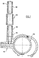
- connection socket 110 to connect, via a lateral diversion 112, a secondary pipe 120 and a main pipe 100 carrying for example natural gas for supply homes (individual houses, buildings).
- the driving secondary 120 as is the lateral bypass 112 from the connection 110, are typically made of plastic, by example in polyethylene and preferably have an external diameter identical.
- Secondary pipe 120 must be connected to branch 112 of connection socket 110 and these parts are welded to each other by example by heating via an external sleeve 130, the internal diameter is substantially equal to the external diameter of the pipe secondary 120 and bypass 112 of connection socket 110. So that there is no risk of leakage when the gas passage is restored, the weld must be perfectly sealed.
- FIG. 2 shows a manual device 10 of scraping by rotation around a plastic tube, typically of the bypass 112 of the connection socket 110 and the pipe secondary 120 of figure 1.
- This device 10 is presented as an annular structure 11 (a ring) hollowed out (see Figure 3) and typically made of material plastic (PVC for example) with a main axis xx '(see Figure 4) along which there extends a through passage 20 surrounded by a wall circular 12 of the annular structure 11.
- This annular structure 11 also has a thickness E (see FIG. 4) along the axis xx 'and a width L perpendicular to this same axis (radially).
- the passage 20 has an internal diameter D adapted so that the device 10 can be passed around the tubes 112 and 120 whose surfaces external 115 and 125 are to be scratched, i.e. slightly higher than the external diameter of these tubes.
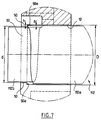
- the zone 52 for restricting the passage 20 formed by the shoulder 50 has a diameter d less than the diameter D the gap of this shoulder.
- the annular structure 11 is also split over its entire thickness E and its entire width L so that the plastic forming said annular structure 11 is actually interrupted by a slit 13.
- This slot 13 substantially diametrically opposite a blade 30 and disposed between zones 16 in the form of hollows provided for taking hand of the device by a user, provides the elasticity necessary for device 10 for absorbing any defects (ovalization) of the element tubular 112 to be scraped, both during installation and during scraping.
- the slot 13 is straight, extends along the axis principal xx 'and has a substantially constant width. She could present in section a slightly V shape.
- the blade 30, preferably metallic and not interchangeable (for cost issues) extends along the main axis xx '. It is inserted (by glued example) in a hollow 14 arranged in the annular structure 11. It has a sharp edge 32 projecting slightly from the surface 12 of the annular structure, inside the passage 20, in the direction of the axis main xx 'of the device 10.
- the annular structure 11 has an opening 15 which does not extend over all its thickness E but which crosses its entire width L, in order to allow a plastic chip 40 formed during scraping to escape from the device 10.
- the blade 30 has in section a curved notch 34 cooperating with a protuberance 17 of complementary shape provided in the hollow 14 of the annular structure 11 in order to block the blade 30 in rotation along the axis xx 'during scraping (if the blade is also glued, it will be held even more firmly).
- the blade 30 also has in section, near its edge sharp 32, a curved notch 36 intended to improve scraping as well as the formation and development of the chip.
- the cutting edge 32 of the blade 30 has a recess axial 38, substantially at the limit of the opening 15. Thus, the cutting edge 32 extends over a lesser distance than the blade inside the hollow 14. The part without sharp edge has no scraping function, it completes the useful surface of the blade for effective support in the cavity 14. The cutting edge 32 is disposed entirely in the extension of the recess 15.
- the shapes intaglio 16 are provided (see Figures 2 and 3), so that a user can come and place your fingers, preferably your thumb and index finger or your thumb and major, in order to rotate the device 10 without slipping, and to be able to play manually, thanks to the elasticity slot 13, on the pressure exerted on said device.
- these shapes 16 are rounded, concave and they are diametrically opposed.
- the passage restriction 52 has a diameter d which is less than the diameter of the tube before scraping. So a non-scraped part 112a of the tube abuts against a radial face 50a of shoulder 50.
- the height s of the projection formed by the cutting edge 32 by relative to the wall 12 being greater than the height h of the shoulder 50, a scraped part 112b of the tube passes unhindered through restriction 52 of passage.
- the height h of the shoulder 50 is here equivalent to half the difference in diameters D (from passing away from restriction zone 52 passage) and d (passage at the location of this restriction 52).
- the low unit cost of this mass-produced scraper can make it a disposable material after one or more uses.
- the shoulder extending here over almost the entire circumference of the passage (except at the location of the opening 15), could be discontinuous, constituted in particular by one (of) stud (s).
- the blade could have other cutting edges, be made of other materials, be connected to the annular structure using mechanical means or even be inclined relative to the axis xx '.
- the annular structure could also be metallic or solid.
- the number of concave shapes of the outer surface of the annular structure can be greater than two (4 arranged in opposition by example), especially if the device is of a fairly large size (more of 10 centimeters in diameter for example for scraping tubes of large diameter).
Landscapes
- Engineering & Computer Science (AREA)
- Mechanical Engineering (AREA)
- Cleaning In General (AREA)
- Lining Or Joining Of Plastics Or The Like (AREA)
- Processing And Handling Of Plastics And Other Materials For Molding In General (AREA)
- Knives (AREA)
- Investigating Or Analyzing Materials By The Use Of Ultrasonic Waves (AREA)
- Removal Of Floating Material (AREA)
- Soil Working Implements (AREA)
- Accessories For Mixers (AREA)
- Turning (AREA)
- Supplying Of Containers To The Packaging Station (AREA)
Claims (10)
- Manuelle Vorrichtung (10) zum Schaben durch eine Rotationsbewegung um die äußere Oberfläche (115; 125) eines Rohrs (112; 120) aus Kunststoff, wobei die Vorrichtung (10) umfasst:gekennzeichnet dadurch, dass die Öffnung die ringförmige Struktur durchläuft und teilweise durch eine Schulter (50) blockiert wird, die eine Einschnürungszone (52) für die Öffnung festlegt, wobei diese Schulter eine Höhe (h) in Bezug auf die innere, periphere Oberfläche der ringförmigen Struktur aufweist,eine ringförmige Struktur (11), die eine Öffnung (20) aufweist, welche sich längs einer Hauptachse (xx') erstreckt und durch eine innere, periphere Oberfläche (12) der ringförmigen Struktur begrenzt ist, die dazu bestimmt ist, das Rohr in dicht schließender Form aufzunehmen, um es zu führen,ein Messer (30), das an der ringförmigen Struktur (11) befestigt wird und eine Schneidkante (32) aufweist, welche von der inneren, peripheren Oberfläche übersteht, um in das Innere der Öffnung (20) hineinzuragen,
und zwar geringfügig kleiner als diejenige(n) der Auskragung, die durch die Schneidkante in Bezug auf die innere, periphere Oberfläche der ringförmigen Struktur gebildet wird, so dass die Schulter einen Anschlag für ein nicht geschabtes Stück (112a) des Rohrs bildet und den Durchlass eines geschabten Stücks (112b) des Rohrs durch die Einschnürung gestattet. - Vorrichtung nach Anspruch 1, gekennzeichnet dadurch, dass die Schneidkante sich in axialer Richtung in die Öffnung (20) im Abstand von der Schulter wenigstens bis zur Grenze der Einschnürungszone (52) der Öffnung und sogar zum Teil bis in das Innere dieser Zone (52) erstreckt.
- Vorrichtung nach Anspruch 1 oder Anspruch 2, gekennzeichnet dadurch, dass:die ringförmige Struktur (11) leicht flexibel ist und eine Dicke (E) längs der Hauptachse (xx') und eine Breite (L) in radialer Richtung zu dieser Achse aufweist,die ringförmige Struktur einen radial verlaufenden Schlitz (13) aufweist, der die gesamte Dicke und die gesamte Breite der ringförmigen Struktur durchquert, undder radial verlaufende Schlitz (13) im Wesentlichen dem Messer (30) diametral gegenüberliegt.
- Vorrichtung (10) nach Anspruch 3, gekennzeichnet dadurch, dass der radial verlaufende Schlitz (13) der ringförmigen Struktur (11) sich im Wesentlichen längs der Hauptachse (xx') der ringförmigen Struktur erstreckt.
- Vorrichtung (10) nach einem der vorherigen Ansprüche, gekennzeichnet dadurch, dass:die ringförmige Struktur eine Dicke (E) längs der Hauptachse (xx') und eine Breite (L) in radialer Richtung zu dieser Achse aufweist,die ringförmige Struktur (11) eine radial verlaufende Öffnung (15) aufweist, die sich über ein Stück der Dicke (E) der ringförmigen Struktur und in radialer Richtung über die gesamte Breite (L) der ringförmigen Struktur erstreckt, unddas Messer (30) sich wenigstens teilweise in das Innere oder in die Verlängerung der Öffnung (15) erstreckt, um den Span zu entfernen, der während des Schabens gebildet wird.
- Vorrichtung (10) nach einem der vorherigen Ansprüche, gekennzeichnet dadurch, dass die ringförmige Struktur (11) teilweise ausgespart ist und aus Kunststoff(en) hergestellt ist.
- Vorrichtung (10) nach einem der vorherigen Ansprüche, gekennzeichnet dadurch, dass die ringförmige Struktur (11) auf ihrer äußeren Oberfläche (11a) Vertiefungen (16) aufweist, um die Vorrichtung (10) in die Hand zu nehmen, und insbesondere konkave Vertiefungen, die geeignet sind, um den Daumen und den Zeigefinger oder den Mittelfinger einer Hand aufzunehmen.
- Vorrichtung (10) nach einem der vorherigen Ansprüche, gekennzeichnet dadurch, dass das Messer (30) im Querschnitt eine gebogene Kerbe (36) in der Nähe seiner Schneidkante (32) aufweist.
- Vorrichtung (10) nach einem der vorherigen Ansprüche, gekennzeichnet dadurch, dass das Messer (30) in einen Hohlraum (14) der ringförmigen Struktur (11) geklebt wird und einen Ausschnitt (34) oder eine Ausstülpung aufweist, deren Form geeignet ist, in eine komplementäre Form einzugreifen, die in dem Hohlraum (14) der ringförmigen Struktur (11) hergestellt worden ist, um das Messer (30) während der Rotation seitlich zu blockieren.
- Vorrichtung nach einem der vorherigen Ansprüche, gekennzeichnet dadurch, dassdas Messer (30) sich über eine festgelegte Strecke in den Hohlraum erstreckt, der in der ringförmigen Struktur längs der Hauptachse ausgespart worden ist,die Schneidkante (32) des Messers durch einen Rücksprung (38) unterbrochen ist, so dass das Messer nur über ein Stück der festgelegten Strecke aus der inneren, peripheren Oberfläche der ringförmigen Struktur hervorragt.
Applications Claiming Priority (3)
| Application Number | Priority Date | Filing Date | Title |
|---|---|---|---|
| FR9907945 | 1999-06-22 | ||
| FR9907945A FR2795355B1 (fr) | 1999-06-22 | 1999-06-22 | Dispositif manuel de grattage par rotation autour de la surface externe d'un tube |
| PCT/FR2000/001698 WO2000078486A1 (fr) | 1999-06-22 | 2000-06-20 | Dispositif de grattage d'un tube |
Publications (2)
| Publication Number | Publication Date |
|---|---|
| EP1105238A1 EP1105238A1 (de) | 2001-06-13 |
| EP1105238B1 true EP1105238B1 (de) | 2003-04-02 |
Family
ID=9547152
Family Applications (1)
| Application Number | Title | Priority Date | Filing Date |
|---|---|---|---|
| EP00951617A Expired - Lifetime EP1105238B1 (de) | 1999-06-22 | 2000-06-20 | Abstreifvorrichtung für ein rohr |
Country Status (8)
| Country | Link |
|---|---|
| US (1) | US6434776B1 (de) |
| EP (1) | EP1105238B1 (de) |
| AT (1) | ATE235983T1 (de) |
| CA (1) | CA2341582C (de) |
| DE (1) | DE60001903T2 (de) |
| FR (1) | FR2795355B1 (de) |
| PT (1) | PT1105238E (de) |
| WO (1) | WO2000078486A1 (de) |
Families Citing this family (15)
| Publication number | Priority date | Publication date | Assignee | Title |
|---|---|---|---|---|
| US6698321B2 (en) * | 2001-03-14 | 2004-03-02 | Fritz Oswald | Pipe shaver |
| US7007391B2 (en) * | 2001-10-18 | 2006-03-07 | Entegris, Inc. | Dual containment tubing cutter |
| US20050262697A1 (en) * | 2004-05-25 | 2005-12-01 | Stein Michael A | Cutting device for tubular objects |
| US7300521B2 (en) * | 2004-12-08 | 2007-11-27 | U.S. Greenfiber, Llc | Wall scrubber for blown insulation |
| US7337698B2 (en) * | 2005-04-22 | 2008-03-04 | S & D Machine And Tool | Adjustable pipe shaving device |
| FR2910357B1 (fr) * | 2006-12-20 | 2009-03-06 | Thales Sa | Dispositif de nettoyage de parois internes d'un conduit vehiculant un fluide porteur d'impuretes |
| US8007595B2 (en) * | 2008-02-28 | 2011-08-30 | Welaptega Marine Limited | Method for in-situ cleaning and inspecting of a tubular |
| DE102009030362A1 (de) | 2008-09-02 | 2010-04-01 | Gbz Mannheim Gmbh & Co. Kg | Einspanndorn für ein Schälgerät zur Bearbeitung von Kunststoffrohren oder von mit Kunststoff beschichteten Rohren sowie ein Schälgerät |
| CN102501148B (zh) * | 2011-11-04 | 2015-05-27 | 哈尔滨通能电气股份有限公司 | 汽轮机汽封圈间隙随形修刮装置 |
| US8720070B2 (en) | 2011-11-04 | 2014-05-13 | Reed Manufacturing Company | Pipe peeler |
| US9272502B2 (en) * | 2012-04-20 | 2016-03-01 | Paul J. Flood | Cartridge and tubular container trimming and refinishing apparatus for ink and label removal and method of use |
| US9738003B2 (en) * | 2013-04-19 | 2017-08-22 | Paul J. Flood | Cartridge and tubular container trimming and refinishing apparatus for ink and label removal |
| US9248388B1 (en) * | 2013-09-23 | 2016-02-02 | ISM&M, Inc. | Skimming apparatus |
| US9862031B2 (en) | 2014-05-07 | 2018-01-09 | Georg Fischer Central Plastics Llc | Tube scraper with biased blades |
| US10500646B2 (en) | 2016-04-25 | 2019-12-10 | Georg Fischer Central Plastics Llc | Tube peeling witness groove methods and apparatus |
Family Cites Families (5)
| Publication number | Priority date | Publication date | Assignee | Title |
|---|---|---|---|---|
| DE7908981U1 (de) * | 1979-03-29 | 1979-08-02 | Messer Griesheim Gmbh, 6000 Frankfurt | Rohrschaelwerkzeug |
| ITPZ930004U1 (it) | 1993-10-21 | 1995-04-21 | I Co M A R S N C | Sbavatore per interno ed esterno di tubi in materiale plastico da 25- 32-40-50-56-63-75 millimetri |
| DE4423258C2 (de) * | 1994-07-02 | 1999-04-08 | Gabo Systemtech Gmbh | Schweissverfahren zur Herstellung einer Rohrverbindung |
| US5600862A (en) * | 1996-01-04 | 1997-02-11 | Gas Research Institute | Pipe scraper |
| DE29612667U1 (de) * | 1996-07-22 | 1996-09-12 | Oswald, Friedrich, 86971 Peiting | Schäler mit Plandrehvorrichtung |
-
1999
- 1999-06-22 FR FR9907945A patent/FR2795355B1/fr not_active Expired - Lifetime
-
2000
- 2000-06-20 AT AT00951617T patent/ATE235983T1/de active
- 2000-06-20 EP EP00951617A patent/EP1105238B1/de not_active Expired - Lifetime
- 2000-06-20 WO PCT/FR2000/001698 patent/WO2000078486A1/fr not_active Ceased
- 2000-06-20 DE DE60001903T patent/DE60001903T2/de not_active Expired - Lifetime
- 2000-06-20 US US09/763,378 patent/US6434776B1/en not_active Expired - Lifetime
- 2000-06-20 PT PT00951617T patent/PT1105238E/pt unknown
- 2000-06-20 CA CA002341582A patent/CA2341582C/fr not_active Expired - Lifetime
Also Published As
| Publication number | Publication date |
|---|---|
| EP1105238A1 (de) | 2001-06-13 |
| US6434776B1 (en) | 2002-08-20 |
| WO2000078486A1 (fr) | 2000-12-28 |
| FR2795355A1 (fr) | 2000-12-29 |
| CA2341582A1 (fr) | 2000-12-28 |
| CA2341582C (fr) | 2008-05-06 |
| DE60001903T2 (de) | 2003-12-18 |
| PT1105238E (pt) | 2003-08-29 |
| DE60001903D1 (de) | 2003-05-08 |
| ATE235983T1 (de) | 2003-04-15 |
| FR2795355B1 (fr) | 2001-10-19 |
Similar Documents
| Publication | Publication Date | Title |
|---|---|---|
| CA2341582C (fr) | Dispositif de grattage d'un tube | |
| EP2332716B1 (de) | Vorrichtung für Aufdehnwerkzeug für Zange auf der Maschine, zum Ausführen von Fugen an den Endstücken von Plastik- oder Verbundrohren | |
| EP1273843B1 (de) | Wiederverwendbare Kupplung zum Verbinden von verstärkten Schlauchenden | |
| EP1412107B1 (de) | Dehnungswerkzeug für aufweitzange | |
| FR2701537A1 (fr) | Filtre pour connecteur de tubes et assemblage connecteur ainsi formé. | |
| FR2851634A1 (fr) | Pince de raccord et structure de raccordement de raccord destinees a verifier le raccordement complet entre un raccord et un tuyau | |
| FR3060702A1 (fr) | Circuit de fluide comprenant une premiere canalisation, une deuxieme canalisation et un raccord de liaison et procede de raccordement | |
| FR2804196A1 (fr) | Dispositif de connexion pour conduits | |
| EP1413815B1 (de) | Kupplung für zwei Rohre mit aufgeweiteten Enden | |
| EP0251929B1 (de) | Verbindungsstück zwischen einem starren Element und einem Schlauch | |
| FR2810370A1 (fr) | Procede de nettoyage d'un filtre a particules dans un ensemble de filtrage et regeneration, ensemble pour la mise en oeuvre de ce procede et elements pour cet ensemble | |
| EP0410843A1 (de) | Verbindungsstück für Kunststoffrohre und Montageverfahren | |
| FR2788582A1 (fr) | Dispositif de branchement d'une canalisation de derivation sur une canalisation de transport de fluide | |
| FR2901313A1 (fr) | Dispositif de degazage pour une turbomachine | |
| EP0622144B1 (de) | Fräswerkzeug und Bohrvorrichtung, zum Anbohren von Röhren | |
| EP4209299B1 (de) | Behälter mit mindestens zwei durch einen verbindungsring verbundenen teilen und durch ein reibschweissverfahren erhaltenen schweissnähten und verfahren zur herstellung des tanks | |
| EP0581678A1 (de) | Radiale Spannvorrichtung zum Verbinden von einem Rohr mit einem Rohrende | |
| CH631788A5 (fr) | Dispositif d'attache a elements. | |
| EP0292408A1 (de) | Einstellbare Schelle zur Anpassung an Kühlerschläuche oder ähnliches | |
| FR2648067A1 (fr) | Dispositif de raccordement destine a faciliter la soudure electrique bout a bout de deux elements tubulaires | |
| FR2926232A1 (fr) | Outil de conformage destine a la preparation de tubes | |
| FR2704929A1 (fr) | Raccord tubulaire de canalisation perfectionné et ensemble installé sur un réseau comprenant un tel raccord. | |
| FR2733029A1 (fr) | Dispositif etanche de raccordement rapide de conduite a bague d'accrochage | |
| FR2885673A1 (fr) | Element tubulaire souple | |
| FR2788459A1 (fr) | Dispositif de prepositionnement d'emporte-piece a fixation rapide des elements coupants interchangeables et jumelables |
Legal Events
| Date | Code | Title | Description |
|---|---|---|---|
| PUAI | Public reference made under article 153(3) epc to a published international application that has entered the european phase |
Free format text: ORIGINAL CODE: 0009012 |
|
| 17P | Request for examination filed |
Effective date: 20010219 |
|
| AK | Designated contracting states |
Kind code of ref document: A1 Designated state(s): AT BE CH CY DE DK ES FI FR GB GR IE IT LI LU MC NL PT SE |
|
| AX | Request for extension of the european patent |
Free format text: AL;LT;LV;MK;RO;SI |
|
| GRAG | Despatch of communication of intention to grant |
Free format text: ORIGINAL CODE: EPIDOS AGRA |
|
| 17Q | First examination report despatched |
Effective date: 20011126 |
|
| GRAG | Despatch of communication of intention to grant |
Free format text: ORIGINAL CODE: EPIDOS AGRA |
|
| GRAH | Despatch of communication of intention to grant a patent |
Free format text: ORIGINAL CODE: EPIDOS IGRA |
|
| GRAG | Despatch of communication of intention to grant |
Free format text: ORIGINAL CODE: EPIDOS AGRA |
|
| GRAH | Despatch of communication of intention to grant a patent |
Free format text: ORIGINAL CODE: EPIDOS IGRA |
|
| GRAG | Despatch of communication of intention to grant |
Free format text: ORIGINAL CODE: EPIDOS AGRA |
|
| GRAH | Despatch of communication of intention to grant a patent |
Free format text: ORIGINAL CODE: EPIDOS IGRA |
|
| GRAH | Despatch of communication of intention to grant a patent |
Free format text: ORIGINAL CODE: EPIDOS IGRA |
|
| GRAA | (expected) grant |
Free format text: ORIGINAL CODE: 0009210 |
|
| AK | Designated contracting states |
Designated state(s): AT BE CH CY DE DK ES FI FR GB GR IE IT LI LU MC NL PT SE |
|
| PG25 | Lapsed in a contracting state [announced via postgrant information from national office to epo] |
Ref country code: FI Free format text: LAPSE BECAUSE OF FAILURE TO SUBMIT A TRANSLATION OF THE DESCRIPTION OR TO PAY THE FEE WITHIN THE PRESCRIBED TIME-LIMIT Effective date: 20030402 Ref country code: IE Free format text: LAPSE BECAUSE OF NON-PAYMENT OF DUE FEES Effective date: 20030402 |
|
| REG | Reference to a national code |
Ref country code: GB Ref legal event code: FG4D Free format text: NOT ENGLISH |
|
| REG | Reference to a national code |
Ref country code: CH Ref legal event code: EP |
|
| REG | Reference to a national code |
Ref country code: IE Ref legal event code: FG4D Free format text: FRENCH |
|
| REF | Corresponds to: |
Ref document number: 60001903 Country of ref document: DE Date of ref document: 20030508 Kind code of ref document: P |
|
| REG | Reference to a national code |
Ref country code: CH Ref legal event code: NV Representative=s name: LEMAN CONSULTING S.A. |
|
| PG25 | Lapsed in a contracting state [announced via postgrant information from national office to epo] |
Ref country code: CY Free format text: LAPSE BECAUSE OF FAILURE TO SUBMIT A TRANSLATION OF THE DESCRIPTION OR TO PAY THE FEE WITHIN THE PRESCRIBED TIME-LIMIT Effective date: 20030620 Ref country code: LU Free format text: LAPSE BECAUSE OF NON-PAYMENT OF DUE FEES Effective date: 20030620 |
|
| PG25 | Lapsed in a contracting state [announced via postgrant information from national office to epo] |
Ref country code: MC Free format text: LAPSE BECAUSE OF NON-PAYMENT OF DUE FEES Effective date: 20030630 |
|
| PG25 | Lapsed in a contracting state [announced via postgrant information from national office to epo] |
Ref country code: DK Free format text: LAPSE BECAUSE OF FAILURE TO SUBMIT A TRANSLATION OF THE DESCRIPTION OR TO PAY THE FEE WITHIN THE PRESCRIBED TIME-LIMIT Effective date: 20030702 Ref country code: SE Free format text: LAPSE BECAUSE OF FAILURE TO SUBMIT A TRANSLATION OF THE DESCRIPTION OR TO PAY THE FEE WITHIN THE PRESCRIBED TIME-LIMIT Effective date: 20030702 Ref country code: GR Free format text: LAPSE BECAUSE OF FAILURE TO SUBMIT A TRANSLATION OF THE DESCRIPTION OR TO PAY THE FEE WITHIN THE PRESCRIBED TIME-LIMIT Effective date: 20030702 |
|
| GBT | Gb: translation of ep patent filed (gb section 77(6)(a)/1977) | ||
| LTIE | Lt: invalidation of european patent or patent extension |
Effective date: 20030402 |
|
| PG25 | Lapsed in a contracting state [announced via postgrant information from national office to epo] |
Ref country code: ES Free format text: LAPSE BECAUSE OF FAILURE TO SUBMIT A TRANSLATION OF THE DESCRIPTION OR TO PAY THE FEE WITHIN THE PRESCRIBED TIME-LIMIT Effective date: 20031030 |
|
| REG | Reference to a national code |
Ref country code: IE Ref legal event code: FD4D Ref document number: 1105238E Country of ref document: IE |
|
| BERE | Be: lapsed |
Owner name: GAZ DE FRANCE *GDF SERVICE NATIONAL Effective date: 20030630 |
|
| PLBE | No opposition filed within time limit |
Free format text: ORIGINAL CODE: 0009261 |
|
| STAA | Information on the status of an ep patent application or granted ep patent |
Free format text: STATUS: NO OPPOSITION FILED WITHIN TIME LIMIT |
|
| 26N | No opposition filed |
Effective date: 20040105 |
|
| PG25 | Lapsed in a contracting state [announced via postgrant information from national office to epo] |
Ref country code: BE Free format text: LAPSE BECAUSE OF NON-PAYMENT OF DUE FEES Effective date: 20030630 |
|
| REG | Reference to a national code |
Ref country code: CH Ref legal event code: PFA Owner name: GDF SUEZ SOCIETE ANONYME Free format text: GAZ DE FRANCE (GDF) SERVICE NATIONAL#23, RUE PHILIBERT DELORME#75017 PARIS (FR) -TRANSFER TO- GDF SUEZ SOCIETE ANONYME#12-26 RUE DU DOCTEUR LANCEREAUX#75008 PARIS (FR) |
|
| NLT1 | Nl: modifications of names registered in virtue of documents presented to the patent office pursuant to art. 16 a, paragraph 1 |
Owner name: GDF SUEZ |
|
| REG | Reference to a national code |
Ref country code: FR Ref legal event code: CA Ref country code: FR Ref legal event code: CD Ref country code: FR Ref legal event code: CJ |
|
| REG | Reference to a national code |
Ref country code: DE Ref legal event code: R082 Ref document number: 60001903 Country of ref document: DE Representative=s name: WSL PATENTANWAELTE PARTNERSCHAFTSGESELLSCHAFT, DE |
|
| REG | Reference to a national code |
Ref country code: DE Ref legal event code: R082 Ref document number: 60001903 Country of ref document: DE Representative=s name: WSL PATENTANWAELTE PARTNERSCHAFT MBB, DE Effective date: 20111028 Ref country code: DE Ref legal event code: R081 Ref document number: 60001903 Country of ref document: DE Owner name: GDF SUEZ S.A., FR Free format text: FORMER OWNER: GAZ DE FRANCE (G.D.F.) SERVICE NATIONAL, PARIS, FR Effective date: 20111028 |
|
| REG | Reference to a national code |
Ref country code: AT Ref legal event code: PC Ref document number: 235983 Country of ref document: AT Kind code of ref document: T Owner name: GDF SUEZ, FR Effective date: 20130328 |
|
| REG | Reference to a national code |
Ref country code: FR Ref legal event code: PLFP Year of fee payment: 17 |
|
| REG | Reference to a national code |
Ref country code: FR Ref legal event code: PLFP Year of fee payment: 18 |
|
| REG | Reference to a national code |
Ref country code: FR Ref legal event code: PLFP Year of fee payment: 19 |
|
| PGFP | Annual fee paid to national office [announced via postgrant information from national office to epo] |
Ref country code: PT Payment date: 20180601 Year of fee payment: 19 Ref country code: DE Payment date: 20180522 Year of fee payment: 19 Ref country code: CH Payment date: 20180528 Year of fee payment: 19 |
|
| PGFP | Annual fee paid to national office [announced via postgrant information from national office to epo] |
Ref country code: NL Payment date: 20180528 Year of fee payment: 19 Ref country code: IT Payment date: 20180523 Year of fee payment: 19 Ref country code: FR Payment date: 20180525 Year of fee payment: 19 Ref country code: AT Payment date: 20180524 Year of fee payment: 19 |
|
| PGFP | Annual fee paid to national office [announced via postgrant information from national office to epo] |
Ref country code: GB Payment date: 20180522 Year of fee payment: 19 |
|
| REG | Reference to a national code |
Ref country code: DE Ref legal event code: R119 Ref document number: 60001903 Country of ref document: DE |
|
| PG25 | Lapsed in a contracting state [announced via postgrant information from national office to epo] |
Ref country code: PT Free format text: LAPSE BECAUSE OF NON-PAYMENT OF DUE FEES Effective date: 20191220 |
|
| REG | Reference to a national code |
Ref country code: CH Ref legal event code: PL |
|
| REG | Reference to a national code |
Ref country code: NL Ref legal event code: MM Effective date: 20190701 |
|
| REG | Reference to a national code |
Ref country code: AT Ref legal event code: MM01 Ref document number: 235983 Country of ref document: AT Kind code of ref document: T Effective date: 20190620 |
|
| GBPC | Gb: european patent ceased through non-payment of renewal fee |
Effective date: 20190620 |
|
| PG25 | Lapsed in a contracting state [announced via postgrant information from national office to epo] |
Ref country code: AT Free format text: LAPSE BECAUSE OF NON-PAYMENT OF DUE FEES Effective date: 20190620 Ref country code: GB Free format text: LAPSE BECAUSE OF NON-PAYMENT OF DUE FEES Effective date: 20190620 Ref country code: IT Free format text: LAPSE BECAUSE OF NON-PAYMENT OF DUE FEES Effective date: 20190620 Ref country code: DE Free format text: LAPSE BECAUSE OF NON-PAYMENT OF DUE FEES Effective date: 20200101 Ref country code: NL Free format text: LAPSE BECAUSE OF NON-PAYMENT OF DUE FEES Effective date: 20190701 |
|
| PG25 | Lapsed in a contracting state [announced via postgrant information from national office to epo] |
Ref country code: CH Free format text: LAPSE BECAUSE OF NON-PAYMENT OF DUE FEES Effective date: 20190630 Ref country code: LI Free format text: LAPSE BECAUSE OF NON-PAYMENT OF DUE FEES Effective date: 20190630 |
|
| PG25 | Lapsed in a contracting state [announced via postgrant information from national office to epo] |
Ref country code: FR Free format text: LAPSE BECAUSE OF NON-PAYMENT OF DUE FEES Effective date: 20190630 |
|
| PG25 | Lapsed in a contracting state [announced via postgrant information from national office to epo] |
Ref country code: PT Free format text: LAPSE BECAUSE OF EXPIRATION OF PROTECTION Effective date: 20200701 |
|
| PG25 | Lapsed in a contracting state [announced via postgrant information from national office to epo] |
Ref country code: PT Free format text: LAPSE BECAUSE OF NON-PAYMENT OF DUE FEES Effective date: 20190620 |
|
| PG25 | Lapsed in a contracting state [announced via postgrant information from national office to epo] |
Ref country code: PT Free format text: LAPSE BECAUSE OF NON-PAYMENT OF DUE FEES Effective date: 20190620 |