EP1105246B1 - Schweisskopf - Google Patents
Schweisskopf Download PDFInfo
- Publication number
- EP1105246B1 EP1105246B1 EP99933684A EP99933684A EP1105246B1 EP 1105246 B1 EP1105246 B1 EP 1105246B1 EP 99933684 A EP99933684 A EP 99933684A EP 99933684 A EP99933684 A EP 99933684A EP 1105246 B1 EP1105246 B1 EP 1105246B1
- Authority
- EP
- European Patent Office
- Prior art keywords
- probe
- force
- probe member
- welding apparatus
- workpiece
- Prior art date
- Legal status (The legal status is an assumption and is not a legal conclusion. Google has not performed a legal analysis and makes no representation as to the accuracy of the status listed.)
- Expired - Lifetime
Links
- 238000003466 welding Methods 0.000 title claims abstract description 71
- 239000000523 sample Substances 0.000 claims abstract description 153
- 239000012530 fluid Substances 0.000 claims description 28
- 238000000926 separation method Methods 0.000 claims description 12
- 238000000034 method Methods 0.000 claims description 9
- 238000006073 displacement reaction Methods 0.000 claims description 5
- 239000012809 cooling fluid Substances 0.000 claims description 3
- 238000001816 cooling Methods 0.000 claims 2
- 239000002826 coolant Substances 0.000 claims 1
- 238000005242 forging Methods 0.000 description 9
- 238000004886 process control Methods 0.000 description 6
- 238000005452 bending Methods 0.000 description 3
- 238000005259 measurement Methods 0.000 description 3
- 230000003287 optical effect Effects 0.000 description 3
- 238000003756 stirring Methods 0.000 description 2
- 229910000831 Steel Inorganic materials 0.000 description 1
- 238000004891 communication Methods 0.000 description 1
- 230000006870 function Effects 0.000 description 1
- 238000007789 sealing Methods 0.000 description 1
- 239000010959 steel Substances 0.000 description 1
Images


Classifications
-
- B—PERFORMING OPERATIONS; TRANSPORTING
- B23—MACHINE TOOLS; METAL-WORKING NOT OTHERWISE PROVIDED FOR
- B23K—SOLDERING OR UNSOLDERING; WELDING; CLADDING OR PLATING BY SOLDERING OR WELDING; CUTTING BY APPLYING HEAT LOCALLY, e.g. FLAME CUTTING; WORKING BY LASER BEAM
- B23K20/00—Non-electric welding by applying impact or other pressure, with or without the application of heat, e.g. cladding or plating
- B23K20/12—Non-electric welding by applying impact or other pressure, with or without the application of heat, e.g. cladding or plating the heat being generated by friction; Friction welding
- B23K20/122—Non-electric welding by applying impact or other pressure, with or without the application of heat, e.g. cladding or plating the heat being generated by friction; Friction welding using a non-consumable tool, e.g. friction stir welding
- B23K20/1245—Non-electric welding by applying impact or other pressure, with or without the application of heat, e.g. cladding or plating the heat being generated by friction; Friction welding using a non-consumable tool, e.g. friction stir welding characterised by the apparatus
- B23K20/126—Workpiece support, i.e. backing or clamping
-
- B—PERFORMING OPERATIONS; TRANSPORTING
- B23—MACHINE TOOLS; METAL-WORKING NOT OTHERWISE PROVIDED FOR
- B23K—SOLDERING OR UNSOLDERING; WELDING; CLADDING OR PLATING BY SOLDERING OR WELDING; CUTTING BY APPLYING HEAT LOCALLY, e.g. FLAME CUTTING; WORKING BY LASER BEAM
- B23K20/00—Non-electric welding by applying impact or other pressure, with or without the application of heat, e.g. cladding or plating
- B23K20/12—Non-electric welding by applying impact or other pressure, with or without the application of heat, e.g. cladding or plating the heat being generated by friction; Friction welding
- B23K20/122—Non-electric welding by applying impact or other pressure, with or without the application of heat, e.g. cladding or plating the heat being generated by friction; Friction welding using a non-consumable tool, e.g. friction stir welding
- B23K20/123—Controlling or monitoring the welding process
-
- B—PERFORMING OPERATIONS; TRANSPORTING
- B23—MACHINE TOOLS; METAL-WORKING NOT OTHERWISE PROVIDED FOR
- B23K—SOLDERING OR UNSOLDERING; WELDING; CLADDING OR PLATING BY SOLDERING OR WELDING; CUTTING BY APPLYING HEAT LOCALLY, e.g. FLAME CUTTING; WORKING BY LASER BEAM
- B23K20/00—Non-electric welding by applying impact or other pressure, with or without the application of heat, e.g. cladding or plating
- B23K20/12—Non-electric welding by applying impact or other pressure, with or without the application of heat, e.g. cladding or plating the heat being generated by friction; Friction welding
- B23K20/122—Non-electric welding by applying impact or other pressure, with or without the application of heat, e.g. cladding or plating the heat being generated by friction; Friction welding using a non-consumable tool, e.g. friction stir welding
- B23K20/1245—Non-electric welding by applying impact or other pressure, with or without the application of heat, e.g. cladding or plating the heat being generated by friction; Friction welding using a non-consumable tool, e.g. friction stir welding characterised by the apparatus
- B23K20/125—Rotary tool drive mechanism
-
- B—PERFORMING OPERATIONS; TRANSPORTING
- B23—MACHINE TOOLS; METAL-WORKING NOT OTHERWISE PROVIDED FOR
- B23K—SOLDERING OR UNSOLDERING; WELDING; CLADDING OR PLATING BY SOLDERING OR WELDING; CUTTING BY APPLYING HEAT LOCALLY, e.g. FLAME CUTTING; WORKING BY LASER BEAM
- B23K20/00—Non-electric welding by applying impact or other pressure, with or without the application of heat, e.g. cladding or plating
- B23K20/12—Non-electric welding by applying impact or other pressure, with or without the application of heat, e.g. cladding or plating the heat being generated by friction; Friction welding
- B23K20/122—Non-electric welding by applying impact or other pressure, with or without the application of heat, e.g. cladding or plating the heat being generated by friction; Friction welding using a non-consumable tool, e.g. friction stir welding
- B23K20/1245—Non-electric welding by applying impact or other pressure, with or without the application of heat, e.g. cladding or plating the heat being generated by friction; Friction welding using a non-consumable tool, e.g. friction stir welding characterised by the apparatus
- B23K20/1255—Tools therefor, e.g. characterised by the shape of the probe
-
- B—PERFORMING OPERATIONS; TRANSPORTING
- B23—MACHINE TOOLS; METAL-WORKING NOT OTHERWISE PROVIDED FOR
- B23K—SOLDERING OR UNSOLDERING; WELDING; CLADDING OR PLATING BY SOLDERING OR WELDING; CUTTING BY APPLYING HEAT LOCALLY, e.g. FLAME CUTTING; WORKING BY LASER BEAM
- B23K20/00—Non-electric welding by applying impact or other pressure, with or without the application of heat, e.g. cladding or plating
- B23K20/12—Non-electric welding by applying impact or other pressure, with or without the application of heat, e.g. cladding or plating the heat being generated by friction; Friction welding
- B23K20/122—Non-electric welding by applying impact or other pressure, with or without the application of heat, e.g. cladding or plating the heat being generated by friction; Friction welding using a non-consumable tool, e.g. friction stir welding
- B23K20/1265—Non-butt welded joints, e.g. overlap-joints, T-joints or spot welds
Definitions
- the present invention relates to a welding apparatus and a method of welding a joint between first and second workpiece sections according to the preamble of claims 1 and 17 respectively (see, for example, EP 0810055 ), for friction stir welding applications.
- Friction stir welding is a process of welding component parts together using friction heat generated at a welding joint to form a plasticized region which solidifies joining workpiece sections.
- a welding head is used to generate friction heat along a welding joint.
- the welding head includes a welding probe which is inserted into a joint between workpiece sections.
- the probe includes a pin that is inserted into the joint and a shoulder which is urged against an upper surface of the workpiece. The pin and shoulder spin to generate friction heat to form a plasticize region along the joint for welding operation.
- a workpiece is supported by a rigid table or backplate typically formed of a steel plate.
- Rigid backplate stabilizes the actuation force of the upper shoulder to maintain the integrity of the workpiece so that the workpiece does not bend or deform under the load.
- the welded portion should extend the entire thickness of the workpiece. To assure that the weld extends the entire thickness, sufficient friction heat must be generated between upper and lower surfaces of the workpiece so that the plasticized region extends between upper and lower surfaces of the workpiece.
- the thickness of a workpiece can vary along the joint. Variations in the workpiece thickness can vary pin depth or extension into the workpiece joint. If pin depth does not extend sufficient thickness, the plasticized region does not extend the entire thickness of the workpiece causing stress notches in the joint. For a smaller thickness, pin can extend too close to the backplate so that workpiece becomes joined to the backplate as a result of the welding operation.
- the present invention relates to a welding apparatus according to claim 1, with adjustable probe or pin depth to compensate for variations in workpiece thickness.
- the present invention relates to a welding method according to claim 17.
- FIG. 1 schematically illustrates an embodiment of a welding probe 50 for friction welding application.
- Welding probe 50 welds workpiece sections 52, 54 at joint 56.
- Welding probe 50 is connected to a spindle drive 58 to rotate probe 50 for welding operation.
- welding probe 50 includes an upper probe member 60, a lower probe member 62 and a probe pin 64.
- lower probe member 62 is rigidly connected to probe pin 64 and is movable therewith.
- Lower probe member 62 and probe pin 64 are slideably supported as illustrated by arrow 66 relative to upper probe member 60 for adjusting pin 64 extension relative to upper probe member 60 for use for workpieces of various thickness and for compensating for thickness variations in a workpiece as will be explained.
- upper probe member 60 includes an upper shoulder 72 and lower probe member 62 includes a lower shoulder 74.
- upper probe member 60 is supported so that shoulder 72 abuts an upper surface 76 of workpiece sections 52, 54.
- Pin 64 extends through joint 56 and shoulder 74 of lower probe member 62 abuts a lower surface 78 of the workpiece sections 52, 54.
- An upper forge actuator 80 is coupled to the upper probe member 60 and a lower forge actuator 82 is coupled to the lower probe member 62 and pin 64.
- probe 50 rotates and upper and lower forge actuators 80, 82 supply forging forces Fg 1 , Fg 2 to upper and lower probe members 60, 62 as illustrated by arrows Fg 1 , Fg 2 respectively.
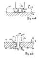
- a profile of plasticize region 92 formed by a prior art probe tapers from a thicker region 94 at an upper surface 76 of the workpiece to a thin region 96 proximate to a lower surface 78 of the workpiece. Stress notches or root openings form if the weld does not extend the entire thickness of the workpiece.
- upper and lower probe members 60, 60 form a plasticized region 98 that includes thicker regions 100, 102 at the upper and lower surfaces 76, 78 and a taper center region 104.
- Fg T
- Upper and lower forge actuators 80, 82 and spindle drive 58 are coupled to controller 106 as schematically illustrated in FIG. 1 for operation. Controller operates upper and lower forge actuators 80, 82 to maintain upper and lower probe members 60, 62 or shoulders 72, 74 in abutment with upper and lower surfaces of the workpiece to compensate for variations in workpiece thickness and profile and to provide a balanced load on opposed surfaces of the workpiece. Controller 106 can be a digital controller or an analog controller set to supply a balanced forging force for upper and lower actuators. A digital controller 106 includes a processor and memory four storing programmed instructions.
- controller operates lower forge actuator 82 to maintain appropriate spacing between upper and lower probe members 60, 62 to adjust pin 64 depth relative to workpiece thickness and variations in workpiece thickness.
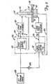
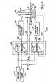
- FIG. 3 illustrates a simplified embodiment for controlling operation of upper and lower forge actuators 80, 82.
- controller 106 uses an input or command forging force 108, which is used to control upper and lower actuators 80, 82.
- Controller 106 includes upper and lower process control 110, 112 which provides operating control to upper and lower forge actuators 80, 82 as illustrated by lines 114, 116 based upon input parameters 108, 109 and control feedback 118, 120.
- feedback 118, 120 includes force feedback as will be explained to maintain a balanced load to the workpiece to limit deformation or bending of the workpiece.
- welding probe provides a plasticized profile having thicker regions relative to upper and lower surfaces 76, 78 of the workpiece to provide a relatively rigid weld joint across the thickness of the workpiece joint, while rigidly supporting the workpiece to limit bending and distortion.
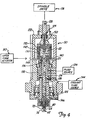
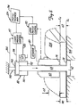
- FIG. 4 is a detailed cross-sectional view of an embodiment of a welding probe 50 including actuatable upper and lower probe members 60, 62.
- probe 50 includes an outer housing 122 and an inner housing 124 rotationally connected to outer housing by bearings 125.
- Upper probe member 60 is formed by inner housing 124.
- Pin 64 is slidably supported in housing 124 via rod 126.
- Probe member 62 is connected to pin 64 to slidably support lower shoulder 74 relative to upper shoulder 72 formed by housing 124.
- Spindle shaft 128 is coupled to housing 124 to rotate housing 124 (upper probe member 60, lower probe member 62 and pin 64) by operation of spindle drive 58 for welding operation.
- spindle drive 58 includes an inline torque transducer for spindle control.
- Spindle control includes simultaneous torque and RPM (revolutions per minute) control.
- upper forge actuator 80 is connected to outer housing 122 to position and actuator upper probe member 60 as will be explained.
- lower forge actuator 82 is a fluid actuator supported in inner housing 124 and coupled to rod 126 connected to lower probe member 62 and pin 64.
- Fluid actuator includes an actuation chamber 130 and piston 132.
- Rod 126 is connected to piston 132 operable in chamber 130.
- Actuator fluid is delivered to chamber 130 from fluid source 134 for bi-directional movement as illustrated by arrow 136.
- Fluid is delivered from fluid source 134 to rotating housing 124 by fluid commutator or slip rings 138.
- Fluid is delivered through channels 140, 142 for bi-directional actuation as illustrated by arrow 136.
- fluid source 134 is a hydraulic fluid although other fluids can be used.
- cooling fluid is supplied from a cooling fluid source 144 to channels 146 in the probe through fluid commutator 138 for temperature control during welding operation.
- Housing 122 includes upper and lower portions separated by a sealing ring 148 for operating fluid containment.
- a displacement sensor 150 (for example, a linear voltage displacement transducer "LVDT") is coupled to rod 126 for position feedback control for pin 64 extension and separation distance between upper and lower probe members 60, 62 as will be explained.
- probe housing 122 is supported for movement along a probe track 152 supported by a welding fixture 154.
- Fixture includes a base 156, and posts 160, 162 which extend from base 156 to support probe track 150 above a workpiece table or backplate 164.
- Probe track 152 is movably coupled to tracks 166, 168 along posts 160, 162 to raise and lower probe 50 as illustrated by arrow 170 for welding operation.
- Table 164 includes a groove 172 or alternately two separately spaced table sections can be used to support the workpiece. Workpiece joint is aligned with groove 172 or separation for placement of the lower probe member 62 underneath the workpiece supported by table 164.
- probe track 152 supports probe 50 for movement along a welding joint of a workpiece supported by table 164 as illustrated by arrow 174.
- Fluid actuators 176, 178 are coupled to probe track 152 to raise and lower track 152 and probe 50 as illustrated by arrow 170. Actuators 176, 178 position probe 50 relative to workpiece and supply forging force to upper probe member 60 through housing 122. Although a particular fixture is shown, application is not limited to the particular fixture.
- table 164 can be movably supported relative to base 180 as illustrated by arrows 180 for probe placement along a welding joint. Bi-directional placement of the probe as illustrated by arrows 180 facilitates complex welding operation along a curved joint in addition to straight line welding along a straight joint. Operation of the actuators 176, 178 can be independently controlled to vary rake angle 184 of the probe for contour welding operations, as will be explained.
- force feedback 118 for upper probe member 60 is measured by force transducer 188 connected in series with force actuator 80 (fluid actuators 176, 178) and upper probe member 60.
- Force feedback 120 for lower probe member 62 is measured by a pressure sensor assembly for measuring pressure differential between chamber portions 190, 192 of fluid actuator 82.
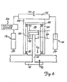
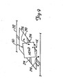
- FIG. 7 illustrates a control schematic for force and position control.
- upper and lower process control 110, 112 receive and process force 108, 109 and position 194, 196 input or command and force 118, 120 and position feedback 198, 200.
- Upper and lower process control 110, 112 includes mode switching for switching between force and position control. Mode switching includes a mode controller 202 or operating actuator 80, 82 between force and position control to maintain force and position parameter within command parameters or limits.
- Mode controller 202 switches mode control between force and position control based upon the force and position error between the program commands 108, 109, 194, 196 and feedback 118, 120, 198, 200.
- mode controller 202 provides force control to maintain force feedback relative to command parameters and switches to position if force feedback 118, 120 is within command parameters 108, 109 and provides position control to maintain position feedback within command parameter and switches to force control when position feedback 198, 200 is within command parameters.
- a proportional integrated controller (DID) provides force and position control and bumpless mode switching between force and position control.
- position feedback 198 can be used to maintain minimum separation ⁇ z between upper and lower probe members 60, 62 based upon workpiece thickness ⁇ t.
- ⁇ z can be controlled based upon preprogrammed command parameters based upon the profile of the workpiece.
- upper and lower process control 110, 112 adjust the position of upper and lower probe members 60, 62 to adjust ⁇ z (separation between upper and lower probe members 60, 62) to correspond to workpiece thickness or minimum separation command parameter.
- the position of lower probe is fixed relative to a workpiece supported by table 164.
- actuator 82 adjusts the position of upper probe member 62 for ⁇ z, and the position of the probe member 60 is also adjusted the same increment as lower probe member 62 by actuator 80 to compensate for the adjustment of lower probe member 62 to maintain the elevation of lower probe member 62 aligned with table 164.
- Position feedback can be used to compensate for profile or dimension changes in the workpiece based upon position commands.
- upper and lower probe members 60, 62 can be adjusted relative to workpiece profile data 204.
- Workpiece profile data ⁇ z 204 can be measured or downloaded off-line or during the welding process by various sensors such as optical sensors to provide position commands 194 for operation.
- the thickness of the workpiece may fluctuate or the thickness may increase ⁇ t.
- position feedback 198, 200 from upper and lower probe members 60, 62, as illustrated in FIG. 7 , and position commands can be used by controllers for placement of upper and lower probe members in abutment with upper and lower workpiece surfaces 76, 78.
- z u , z 1 and ⁇ z can be used for placement of upper and lower probe members 60, 62 based upon position feedback z u , ⁇ z and position commands for z u , ⁇ z where:
- Position commands for z u, z 1 , and ⁇ z can be derived from workpiece image or profile data which is uploaded to controller memory for execution or can be derived during the welding process via various sensors such as laser or optical sensors.
- head is flexibly supported to flexibly couple the head (upper and lower probe members) to follow the contour of the workpiece for adapting head 50 for welding complex shapes and forms.
- head 50 is flexibly supported to pitch and roll relative to an x axis by first and second frame members 210, 212 for sloped or contour welding of surface 208.
- Head 50 is pivotally connected first frame member at trunions 214 to roll relative to the x-axis as illustrated by arrow 216.
- Frame member 210 is pivotally connected to frame member 212 to support the head 50 to pitch as illustrated by arrow 218.
- pitch and roll actuators 220, 222 adjust the position of the head 50 so that the surface of the head 50 (for example, upper and lower shoulders 72, 74) are normal to the surface of the workpiece for contour welding via operation by controller 106 based upon programmed data or profile measurements received during the welding operation via optical or laser sensors.
- probe members have been described relative to an upper and lower orientation, it should be understood, that probe members are not restricted to an upper and lower orientation and the upper and lower probe members can be oriented in any opposed relation.
Landscapes
- Engineering & Computer Science (AREA)
- Mechanical Engineering (AREA)
- Pressure Welding/Diffusion-Bonding (AREA)
- Resistance Welding (AREA)
- Arc Welding In General (AREA)
- Lining Or Joining Of Plastics Or The Like (AREA)
Claims (18)
- Schweißvorrichtung (50) mit:einem Gehäuse (124);einem rotierenden Kopf (50) mit einem rotierenden ersten Kopfelement (60) mit einer in eine erste Richtung orientierten ersten Schulter (72); einem relativ zum ersten Kopfelement (60) beweglichen rotierenden zweiten Kopfelement (62) mit einer zweiten Schulter (74), die in eine der ersten Schulter (72) entgegengesetzte zweite Richtung orientiert ist, wobei die erste und die zweite Schulter (72, 74) voneinander beabstandet sind, so dass ein Zwischenraum dazwischen gebildet wird; und einem mit dem zweiten Kopfelement (62) verbundenen und im Zwischenraum zwischen der ersten und der zweiten Schulter (72, 74) mit dem zweiten Kopfelement rotierbaren Kopfstift (64);dadurch gekennzeichnet, dass die Schweißvorrichtung (50) aufweist:einen mit dem ersten Kopfelement (60) verbundenen ersten Aktuator (80), der betätigbar ist, um eine erste steuerbare Kraft in die erste Richtung auf das erste Kopfelement (60) auszuüben;einen mit dem in einem Kanal des ersten Kopfelements (60) beweglich gehaltenen Kopfstift (64) verbundenen zweiten Aktuator (82) zum Ausüben einer zweiten steuerbaren Kraft in die zweite Richtung über den relativ zum Gehäuses (124) drehbaren Kopfstift (64) auf die zweite Schulter (74) des zweiten Kopfelements (62); undeine mit dem ersten und dem zweiten Aktuator (80, 82) betrieblich verbundene Steuerung (106), die dafür konfiguriert ist, den ersten und den zweiten Aktuator (80, 82) zu steuern, um die erste ausgleichende steuerbare Kraft und die der ersten ausgleichenden steuerbaren Kraft entgegenwirkende zweite ausgleichende steuerbare Kraft in die erste Richtung bzw. in die der ersten Richtung entgegengesetzte zweite Richtung auszuüben.
- Schweißvorrichtung (50) nach Anspruch 1, wobei der zweite Aktuator (82) ein Fluidaktuator (82) mit einem Fluidkommutator zum Bereitstellen einer Fluidverbindung zwischen einer Fluidquelle und dem Fluidaktuator (82) ist, der mit dem bezüglich des Gehäuses (124) rotierbaren Kopfstift (64) verbunden ist.
- Schweißvorrichtung (50) nach Anspruch 1 mit einem mit dem Kopfstift (64) verbundenen Abstandsensor (150) zum Messen des Zwischenraums zwischen der ersten und der zweiten Schulter (72, 74).
- Schweißvorrichtung (50) nach Anspruch 2 mit einer mit einer Fluidaktuatorkammer (130) des Fluidaktuators (82) verbundenen Drucksensoranordnung zum Messen eines Betätigungsdrucks zum Steuern des Betriebs des zweiten Kopfelements (62).
- Schweißvorrichtung (50) nach Anspruch 1, mit im rotierenden Kopf (50) ausgebildeten Kühlkanälen (146) und einer Fluidverbindung von einer Kühlmittelfluidquelle (144) zu den Kühlkanälen (146) im rotierenden Kopf (50) zum Zuführen von Kühlfluid für einen Schweißvorgang zum rotierenden Kopf (50).
- Schweißvorrichtung (50) nach Anspruch 1, mit:einer mit der Steuerung (106) und dem ersten Aktuator (80) verbundenen ersten Kraftrückmeldung (120);
undeiner mit der Steuerung (106) und dem zweiten Aktuator (82) verbundenen zweiten Kraftrückmeldung (118), wobei die Steuerung (106) den ersten und den zweiten Aktuator (80, 82) basierend auf der ersten und der zweiten Kraftrückmeldung (118, 120) steuert. - Schweißvorrichtung (50) nach Anspruch 6, wobei die Steuerung (106) eine Größe des Zwischenraums zwischen der ersten und der zweiten Schulter (72, 74) basierend auf der ersten und der zweiten Kraftrückmeldung (118, 120) für den ersten und den zweiten Aktuator (80, 82) steuert, um gemäß einer Werkstückdicke einen gewünschten Abstand zwischen der ersten und der zweiten Schulter (72, 74) bereitzustellen.
- Schweißvorrichtung (50) nach Anspruch 6, wobei die erste und/oder die zweite Kraftrückmeldung (118, 120) durch einen Kraftaufnehmer (188) gemessen wird.
- Schweißvorrichtung (50) nach Anspruch 6, wobei die erste und/oder die zweite Kraftrückmeldung (118, 120) basierend auf dem Betätigungsdruck des ersten bzw. des zweiten Aktuators (80, 82) gemessen wird.
- Schweißvorrichtung (50) nach Anspruch 1, mit einer mit dem ersten und dem zweiten Kopfelement (60, 62) verbundenen Positionsrückmeldung,
wobei die Steuerung (106) dafür konfiguriert ist, eine Größe des Zwischenraums zwischen der ersten und der zweiten Schulter (72, 74) basierend auf der Positionsrückmeldung für das erste und das zweite Kopfelement (60, 62) zu steuern. - Schweißvorrichtung (50) nach Anspruch 1, mit einer mit dem ersten und dem zweiten Aktuator (80, 82) und der Steuerung (106) verbundenen Kraftrückmeldung (118, 120) zur Kraftsteuerung und einer mit dem ersten und dem zweiten Kopfelement (60, 62) verbundenen Positionsrückmeldung (198, 200) zur Positionssteuerung,
wobei die Steuerung (106) dafür konfiguriert ist, eine Größe des Zwischenraums zwischen der ersten und der zweiten Schulter (72, 74) basierend auf der Kraftrückmeldung (118, 120) und der Positionsrückmeldung (198, 200) gemäß einer Werkstückdicke zu steuern. - Schweißvorrichtung (50) nach Anspruch 11, wobei die Steuerung (106) dafür geeignet ist, zwischen einem Kraft- und einem Positionssteuerungsmodus umzuschalten.
- Schweißvorrichtung (50) nach Anspruch 1, wobei die Steuerung (106) Positionsbefehle für Δz, z1 und/oder z2 empfängt, wobei Δz einen Abstand zwischen dem ersten und dem zweiten Kopfelement (60, 62), z1 eine Position des ersten Kopfelements (60) und z2 eine Position des zweiten Kopfelements (62) bezeichnen, um eine Größe des Zwischenraums zwischen der ersten und der zweiten Schulter (72, 74) zu steuern.
- Schweißvorrichtung (50) nach Anspruch 11, wobei die Steuerung (106) Profildaten (204) enthält, und wobei die Steuerung (106) dafür konfiguriert ist, eine Position des ersten und des zweiten Kopfelements (60, 62) basierend auf den Profildaten (204) und der Positionsrückmeldung (198, 200) zu steuern.
- Schweißvorrichtung (50) nach Anspruch 14, wobei die Profildaten (204) ein in einem Speicher gespeichertes Bild eines Werkstückprofils enthalten.
- Schweißvorrichtung (50) nach Anspruch 1, wobei der Kopfstift (64) mit dem zweiten Kopfelement (62) starr verbunden ist und im Kanal gleitend gehalten wird, um das zweite rotierende Kopfelement (62) relativ zum ersten Kopfelement (60) beweglich zu halten, um den Zwischenraum zwischen der ersten und der zweiten Schulter (72, 74) des ersten und des zweiten Kopfelements (60, 62) einzustellen.
- Verfahren zum Verschweißen einer Verbindungsstelle zwischen einem ersten und einem zweiten Werkstückabschnitt (52, 54) durch Drehen eines Kopfes (50), der ein erstes Kopfelement (60) mit einer in eine erste Richtung orientierten ersten Schulter (72) und ein zweites Kopfelement (62) mit einer zweiten Schulter (74) aufweist, die in eine der ersten Schulter (72) entgegengesetzte zweite Richtung orientiert ist, wobei das erste Kopfelement (60) und das zweite Kopfelement (62) in der Verbindungsstelle zwischen den Werkstückabschnitten (52, 54) angeordnet werden, so dass die erste Schulter (72) an ersten Oberflächen des ersten und des zweiten Werkstückabschnitts (52, 54) anliegt und die zweite Schulter (74) an den ersten Oberflächen der Werkstückabschnitte (52, 54) gegenüberliegenden zweiten Oberflächen des ersten und des zweiten Werkstückabschnitts (52, 54) anliegt;
dadurch gekennzeichnet, dass das Verfahren die Schritte aufweist:Drehen des Kopfes beim Ausüben einer ersten ausgleichenden steuerbaren Kraft auf das erste Kopfelement (60);Drehen des Kopfes beim Ausüben einer zweiten ausgleichenden steuerbaren Kraft über einen in einem Kanal des ersten Kopfelements (60) beweglichen Kopfstift (64) auf das zweite Kopfelement (62), wobei die zweite ausgleichende steuerbare Kraft der ersten ausgleichenden steuerbaren Kraft entgegenwirkt, um automatisch gegenwirkende Kräfte für einen Schweißvorgang bereitzustellen;Bereitstellen einer ersten Kraft- oder Positionsrückmeldung (118, 198) für das erste Kopfelement (60) und einer zweiten Kraft- oder Positionsrückmeldung (120, 200) für das zweite Kopfelement (62); undEinstellen der ersten oder der zweiten ausgleichenden steuerbaren Kraft, die auf das erste und das zweite Kopfelement (60, 62) ausgeübt werden, basierend auf der ersten oder der zweiten Kraft- oder Positionsrückmeldung (118, 120; 198, 200). - Verfahren nach Anspruch 17, ferner mit dem Schritt des Einstellens eines Trennabstands zwischen dem ersten und dem zweiten Kopfelement (60, 62) gemäß einer Dicke der Werkstückabschnitte (52, 54).
Applications Claiming Priority (3)
| Application Number | Priority Date | Filing Date | Title |
|---|---|---|---|
| US9233298P | 1998-07-09 | 1998-07-09 | |
| US92332P | 1998-07-09 | ||
| PCT/US1999/015148 WO2000002699A1 (en) | 1998-07-09 | 1999-07-08 | Welding head |
Publications (3)
| Publication Number | Publication Date |
|---|---|
| EP1105246A1 EP1105246A1 (de) | 2001-06-13 |
| EP1105246A4 EP1105246A4 (de) | 2007-05-02 |
| EP1105246B1 true EP1105246B1 (de) | 2011-04-27 |
Family
ID=22232725
Family Applications (1)
| Application Number | Title | Priority Date | Filing Date |
|---|---|---|---|
| EP99933684A Expired - Lifetime EP1105246B1 (de) | 1998-07-09 | 1999-07-08 | Schweisskopf |
Country Status (9)
| Country | Link |
|---|---|
| US (1) | US6199745B1 (de) |
| EP (1) | EP1105246B1 (de) |
| AT (1) | ATE507025T1 (de) |
| CA (1) | CA2336828C (de) |
| DE (1) | DE69943391D1 (de) |
| DK (1) | DK1105246T3 (de) |
| ES (1) | ES2364950T3 (de) |
| PT (1) | PT1105246E (de) |
| WO (2) | WO2000002704A1 (de) |
Families Citing this family (125)
| Publication number | Priority date | Publication date | Assignee | Title |
|---|---|---|---|---|
| US6264088B1 (en) * | 1997-05-16 | 2001-07-24 | Esab Ab | Welding assembly for friction stir welding |
| US6421578B1 (en) * | 1999-02-12 | 2002-07-16 | Lockheed Martin Corporation | Stir-friction hot working control system |
| DE50004986D1 (de) * | 1999-03-24 | 2004-02-12 | Framatome Anp Gmbh | Verfahren und vorrichtung zum verschweissen zweier werkstücke |
| US6497355B1 (en) * | 1999-10-13 | 2002-12-24 | The United States Of America As Represented By The Administrator Of The National Aeronautics And Space Administration | System for controlling the stirring pin of a friction stir welding apparatus |
| DE19957136C1 (de) * | 1999-11-18 | 2001-02-08 | Geesthacht Gkss Forschung | Vorrichtung zum Verbinden von Werkstücken nach der Methode des Reibrührschweißens |
| US6460752B1 (en) * | 2000-04-04 | 2002-10-08 | The Boeing Company | Method of friction stir welding with grooved backing member |
| JP3400409B2 (ja) * | 2000-04-28 | 2003-04-28 | マツダ株式会社 | 接合方法及び接合装置 |
| CN1191144C (zh) | 2000-05-08 | 2005-03-02 | 布莱阿姆青年大学 | 摩擦搅拌焊接的超级研磨工具和方法 |
| JP2002066763A (ja) * | 2000-09-01 | 2002-03-05 | Honda Motor Co Ltd | 摩擦撹拌接合装置 |
| JP3763734B2 (ja) * | 2000-10-27 | 2006-04-05 | 株式会社日立製作所 | パネル部材の加工方法 |
| US6676004B1 (en) | 2001-02-13 | 2004-01-13 | Edison Welding Institute, Inc. | Tool for friction stir welding |
| JP4050478B2 (ja) | 2001-03-29 | 2008-02-20 | マツダ株式会社 | 摩擦撹拌を用いた加工制御方法、並びに当該方法を実行するコンピュータプログラム並びに当該コンピュータプログラムを格納した記憶媒体 |
| US7210610B2 (en) * | 2001-06-04 | 2007-05-01 | Brigham Young University | Apparatus and method for performing non-linear friction stir welds on either planar or non-planar surfaces |
| US6732901B2 (en) | 2001-06-12 | 2004-05-11 | Brigham Young University Technology Transfer Office | Anvil for friction stir welding high temperature materials |
| CN1304160C (zh) * | 2001-06-12 | 2007-03-14 | 布莱阿姆青年大学 | 用于摩擦搅拌焊接高温材料的砧板 |
| JP3471338B2 (ja) * | 2001-07-30 | 2003-12-02 | 川崎重工業株式会社 | 摩擦攪拌接合装置 |
| US6660106B1 (en) | 2001-08-22 | 2003-12-09 | The Boeing Company | Methods of manufacture of spin-forming blanks, particularly for fabrication of rocket domes |
| US6543671B2 (en) | 2001-09-05 | 2003-04-08 | Lockheed Martin Corporation | Apparatus and method for friction stir welding using filler material |
| US6708866B2 (en) | 2001-09-26 | 2004-03-23 | Nova-Tech Engineering, Inc. | Method and apparatus for machine tooling, such as friction stir welder |
| SE522075C2 (sv) * | 2001-10-23 | 2004-01-13 | Svensk Kaernbraenslehantering | Förfarande för friktionsomröringssvetsning |
| WO2003045615A2 (en) * | 2001-11-27 | 2003-06-05 | THE UNITED STATES OF AMERICA as represented by the ADMINISTRATOR OF THE NATIONAL AERONAUTICS AND SPACE | Thermal stir welding process and apparatus |
| US6688512B2 (en) * | 2001-12-20 | 2004-02-10 | United Technologies Corporation | Apparatus and method for friction welding |
| SE0200303D0 (sv) * | 2002-02-01 | 2002-02-01 | Esab Ab | Svetshuvud för friktionsomrörningssvetsning |
| US6732900B2 (en) | 2002-04-02 | 2004-05-11 | Mts Systems Corporation | Friction stir welding spindle with axially displaceable spindle shaft |
| US6908690B2 (en) | 2002-04-29 | 2005-06-21 | The Boeing Company | Method and apparatus for friction stir welding |
| JP2004136331A (ja) * | 2002-10-18 | 2004-05-13 | Hitachi Ltd | 摩擦攪拌接合装置及び接合方法 |
| JP2004141898A (ja) * | 2002-10-23 | 2004-05-20 | Hitachi Ltd | 摩擦攪拌接合方法および装置 |
| JP4216048B2 (ja) * | 2002-11-11 | 2009-01-28 | 三菱重工業株式会社 | ボビンツールを用いた摩擦攪拌接合装置とその接合方法 |
| US7270257B2 (en) | 2003-01-30 | 2007-09-18 | Sii Megadiamond, Inc. | Out-of-position friction stir welding of high melting temperature alloys |
| US6758382B1 (en) | 2003-05-02 | 2004-07-06 | The United States Of America As Represented By The Administrator Of The National Aeronautics And Space Administration | Auto-adjustable tool for self-reacting and conventional friction stir welding |
| US7530486B2 (en) | 2003-05-05 | 2009-05-12 | Sii Megadiamond, Inc. | Applications of friction stir welding using a superabrasive tool |
| WO2005084162A2 (en) | 2003-08-04 | 2005-09-15 | Smith International, Inc. | Crack repair using friction stir welding on materials including metal matrix composites, ferrous alloys, non-ferrous alloys, and superalloys |
| US7163136B2 (en) * | 2003-08-29 | 2007-01-16 | The Boeing Company | Apparatus and method for friction stir welding utilizing a grooved pin |
| KR100543160B1 (ko) * | 2003-10-01 | 2006-01-20 | 한국기계연구원 | 박판접합용 표면이동 마찰용접방법 |
| KR100619615B1 (ko) * | 2003-10-27 | 2006-09-01 | 더 보잉 컴파니 | 마찰교반용접 작업을 행하는 시스템 및 연관된마찰교반용접(fsw) 어셈블리, 콘트롤러 및 방법 |
| US7048175B2 (en) * | 2003-12-19 | 2006-05-23 | The Boeing Company | Friction welded structural assembly and preform and method for same |
| US20060032333A1 (en) | 2004-03-24 | 2006-02-16 | Steel Russell J | Solid state processing of industrial blades, edges and cutting elements |
| US20100078224A1 (en) | 2004-05-21 | 2010-04-01 | Smith International, Inc. | Ball hole welding using the friction stir welding (fsw) process |
| DE102004028560B3 (de) * | 2004-06-15 | 2005-11-03 | Gkss-Forschungszentrum Geesthacht Gmbh | Vorrichtung zum Verbinden von Werkstücken nach der Methode des Reibrührschweißens |
| DE102004028553B3 (de) * | 2004-06-15 | 2005-11-03 | Gkss-Forschungszentrum Geesthacht Gmbh | Vorrichtung zum Verbinden von Werkstücken nach der Methode des Reibrührschweißens |
| US7448526B2 (en) * | 2004-08-10 | 2008-11-11 | Transformation Technologies, Inc. | Adapter for friction stir welding |
| CA2582732C (en) | 2004-10-05 | 2012-09-11 | Sii Megadiamond, Inc. | Expandable mandrel for use in friction stir welding |
| JP4420785B2 (ja) | 2004-10-14 | 2010-02-24 | Obara株式会社 | 摩擦撹拌スポット接合装置 |
| US8052030B2 (en) | 2005-01-24 | 2011-11-08 | The Boeing Company | Apparatus for friction stir welding using spindle-in-spindle |
| DE102005029881A1 (de) * | 2005-06-27 | 2006-12-28 | Gkss-Forschungszentrum Geesthacht Gmbh | Vorrichtung und Verfahren zum Reibrührschweißen |
| DE102005029882A1 (de) * | 2005-06-27 | 2006-12-28 | Gkss-Forschungszentrum Geesthacht Gmbh | Vorrichtung zum Reibrührschweißen |
| DE102005032170A1 (de) * | 2005-07-09 | 2007-01-11 | Technische Universität Ilmenau | Rührreibschweißwerkzeug und Verfahren und Anordnung zur online-Kontrolle eines Rührreibschweißprozesses |
| US9511446B2 (en) | 2014-12-17 | 2016-12-06 | Aeroprobe Corporation | In-situ interlocking of metals using additive friction stir processing |
| US8632850B2 (en) | 2005-09-26 | 2014-01-21 | Schultz-Creehan Holdings, Inc. | Friction fabrication tools |
| US8875976B2 (en) | 2005-09-26 | 2014-11-04 | Aeroprobe Corporation | System for continuous feeding of filler material for friction stir welding, processing and fabrication |
| US9266191B2 (en) | 2013-12-18 | 2016-02-23 | Aeroprobe Corporation | Fabrication of monolithic stiffening ribs on metallic sheets |
| US9511445B2 (en) | 2014-12-17 | 2016-12-06 | Aeroprobe Corporation | Solid state joining using additive friction stir processing |
| US20080041921A1 (en) | 2005-09-26 | 2008-02-21 | Kevin Creehan | Friction stir fabrication |
| US8056797B2 (en) | 2005-10-05 | 2011-11-15 | Megastir Technologies | Expandable mandrel for use in friction stir welding |
| US8550326B2 (en) | 2005-10-05 | 2013-10-08 | Megastir Technologies Llc | Expandable mandrel for use in friction stir welding |
| DE102005049865A1 (de) * | 2005-10-11 | 2007-04-12 | Gkss-Forschungszentrum Geesthacht Gmbh | Reibrührschweißwerkzeug mit Gegenlager zur Montage an einer Handhabungseinrichtung |
| JP4327788B2 (ja) * | 2005-11-08 | 2009-09-09 | 本田技研工業株式会社 | 摩擦攪拌接合方法 |
| US20070228104A1 (en) * | 2006-03-31 | 2007-10-04 | Mankus Gary R | Friction stir welding spindle assembly |
| US7686202B1 (en) * | 2006-09-29 | 2010-03-30 | The United States Of America As Represented By The Administrator Of The National Aeronautics And Space Administration | Gimbaled-shoulder friction stir welding tool |
| US7992761B2 (en) * | 2006-10-05 | 2011-08-09 | The Boeing Company | Process control system for friction stir welding |
| US9511461B2 (en) | 2006-10-05 | 2016-12-06 | The Boeing Company | Independent axis ancillary device |
| US7774910B2 (en) * | 2006-10-05 | 2010-08-17 | The Boeing Company | Independent axis clamping apparatus and method |
| US9015948B2 (en) * | 2008-01-19 | 2015-04-28 | The Boeing Company | Joining fuselage skins using friction stir welding |
| US8079276B2 (en) | 2008-04-15 | 2011-12-20 | Spirit Aerosystems, Inc. | Dynamic calibration assembly for a friction stir welding machine |
| US8261959B2 (en) | 2008-09-25 | 2012-09-11 | Embraer S.A. | Friction stir welding spindle downforce and other control techniques, systems and methods |
| US20100072261A1 (en) * | 2008-09-25 | 2010-03-25 | Marcio Fernando Cruz | Friction stir welding spindle downforce and other control techniques, systems and methods |
| EP2398620A4 (de) * | 2009-02-19 | 2017-03-29 | Blue Origin, LLC | Modularer reibschweisskopf sowie zugehörige systeme und verfahren |
| US8878111B2 (en) * | 2009-02-24 | 2014-11-04 | Blue Origin, Llc | Bidirectional control surfaces for use with high speed vehicles, and associated systems and methods |
| JP5535502B2 (ja) * | 2009-03-16 | 2014-07-02 | 川崎重工業株式会社 | 摩擦撹拌接合装置及び方法 |
| DE102009040526B4 (de) | 2009-09-08 | 2017-08-03 | Airbus Defence and Space GmbH | Verfahren und Vorrichtung zur Herstellung eines Bauteils durch Rührreibschweißen, deren Verwendung sowie rührreibgeschweißtes Bauteil |
| US9079674B1 (en) | 2009-09-18 | 2015-07-14 | Blue Origin, Llc | Composite structures for aerospace vehicles, and associated systems and methods |
| CA2779075C (en) | 2009-11-02 | 2016-05-10 | Megastir Technologies Llc | Out of position friction stir welding of casing and small diameter tubing or pipe |
| WO2011073465A1 (es) * | 2009-12-18 | 2011-06-23 | Fundacion Fatronik | Cabezal de maquina herramienta para soldeo por fricción batida con pisador flotante |
| EP2338632A1 (de) * | 2009-12-22 | 2011-06-29 | Harms & Wende GmbH & Co. KG | Reibpunktschweisswerkzeug |
| DE102010027291A1 (de) | 2010-07-16 | 2012-01-19 | Airbus Operations Gmbh | Verfahren und Vorrichtung zum Rührreibschweissen |
| AT509066B1 (de) * | 2010-08-11 | 2011-06-15 | Stirzone Og | Vorrichtung zum reibrührschweissen |
| WO2012029176A1 (ja) * | 2010-09-03 | 2012-03-08 | 三菱日立製鉄機械株式会社 | 摩擦攪拌接合システムおよび摩擦攪拌接合方法 |
| CN103052463B (zh) * | 2010-09-03 | 2015-08-05 | 三菱日立制铁机械株式会社 | 在对接部存在间隙的金属板的双面摩擦搅拌接合方法 |
| JP5374528B2 (ja) * | 2011-02-18 | 2013-12-25 | 三菱重工業株式会社 | 摩擦攪拌接合装置及び摩擦攪拌接合方法 |
| JP5819084B2 (ja) * | 2011-03-29 | 2015-11-18 | 学校法人近畿大学 | 摩擦攪拌加工装置及び摩擦攪拌加工方法 |
| WO2013002869A2 (en) | 2011-04-07 | 2013-01-03 | Schultz-Creehan Holdings, Inc. | System for continuous feeding of filler material for friction stir fabrication and self-reacting friction stir welding tool |
| US8534530B2 (en) | 2011-04-27 | 2013-09-17 | Blue Origin, Llc | Inflatable ring for supporting friction welding workpieces, and associated systems and methods |
| JP2012245542A (ja) * | 2011-05-27 | 2012-12-13 | Mitsubishi Heavy Ind Ltd | 摩擦攪拌接合工具及び摩擦攪拌接合装置 |
| DE102011106506A1 (de) * | 2011-06-15 | 2012-12-20 | Eurocopter Deutschland Gmbh | Schweißwerkzeug zum Verbinden von wenigstens zwei Werkstücken, Schweißverfahren und Werkstück |
| CN104023896B (zh) | 2011-06-22 | 2017-04-26 | 萨帕有限公司 | 具有带不同区域的肩部的搅拌摩擦焊接工具;使用这种工具的方法;利用这种工具焊接的产品 |
| WO2012175127A1 (en) | 2011-06-22 | 2012-12-27 | Sapa Ab | Friction stir welding tool with shoulders having different areas methods using such tool; product welded with such tool |
| DE102011111750B3 (de) * | 2011-08-24 | 2012-12-13 | Technische Universität München | Rührreibschweißvorrichtung sowie Verfahren zum Fügen von Werkstücken mittels eines Rührreibschweißverfahrens |
| AT13050U1 (de) | 2011-08-29 | 2013-05-15 | Stirtec Og | FSW Schweißkopf |
| DE102011112042A1 (de) * | 2011-09-01 | 2013-03-07 | Airbus Operations Gmbh | Rührreibschweißverfahren zur Verbindung von plattenförmigen Werkstücken sowie Vorrichtung hierfür |
| US9216472B2 (en) * | 2011-10-14 | 2015-12-22 | Nippon Sharyo, Ltd. | Friction stir welding apparatus comprising slide plates |
| GB201120274D0 (en) | 2011-11-24 | 2012-01-04 | Welding Inst | Friction stir welding tool |
| CN102626823A (zh) * | 2012-04-24 | 2012-08-08 | 郑英 | 一种中心水冷的搅拌摩擦加工工具 |
| ES2435734B1 (es) * | 2012-05-16 | 2014-10-03 | Loxin 2002, S.L. | Electromandrino con control de fuerza axial para soldadura por fricción y otras aplicaciones |
| CN103801817A (zh) * | 2012-11-15 | 2014-05-21 | 上海航天设备制造总厂 | 一种厚板焊接用双速旋转搅拌工具 |
| US8544714B1 (en) | 2012-11-15 | 2013-10-01 | Fluor Technologies Corporation | Certification of a weld produced by friction stir welding |
| JP5863996B2 (ja) * | 2012-12-19 | 2016-02-17 | 三菱重工業株式会社 | 接合材の製造方法、及び接合用治具 |
| US20140215826A1 (en) * | 2013-02-04 | 2014-08-07 | Forge Tech, Inc. | Valve, pipe and pipe component repair |
| JP6084887B2 (ja) * | 2013-04-16 | 2017-02-22 | 川崎重工業株式会社 | 摩擦撹拌接合装置および摩擦撹拌接合方法 |
| US9987796B2 (en) * | 2013-09-06 | 2018-06-05 | GM Global Technology Operations LLC | Apparatus and methods for joining polymeric composites using a hybrid friction/ultrasound technique for achieving desired weld characteristics |
| DE102014112679A1 (de) * | 2013-09-06 | 2015-03-12 | GM Global Technology Operations LLC (n. d. Gesetzen des Staates Delaware) | Vorrichtung und Verfahren zum Reparieren von unstimmigen Schweissnähten |
| JP6226184B2 (ja) * | 2013-11-07 | 2017-11-08 | 三菱重工業株式会社 | 摩擦撹拌接合方法 |
| US9010613B1 (en) | 2013-12-16 | 2015-04-21 | The Boeing Company | Apparatus for friction stir welding |
| DE102014001050A1 (de) | 2014-01-28 | 2015-07-30 | Grenzebach Maschinenbau Gmbh | Verfahren und Vorrichtung zum Rührreibschweißen bei Materialien unterschiedlicher Dicke und bei Kehlnähten |
| JP6383961B2 (ja) * | 2014-03-26 | 2018-09-05 | 国立大学法人大阪大学 | 摩擦攪拌接合装置及び摩擦攪拌接合方法 |
| DE112015001811T5 (de) | 2014-04-16 | 2017-01-19 | Fanuc Corp. | Rührreibschweiß-Vorrichtung |
| EP2944418B1 (de) * | 2014-05-13 | 2019-03-13 | DEPRAG Schulz GmbH u. Co. | Vorrichtung zum verbinden von bauteilen, insbesondere mittels direktverschrauben, speziell fliesslochschrauben oder mittels reibschweissen, sowie verfahren zum verbinden von bauteilen, insbesondere mittels direktverschrauben oder reibschweissen |
| EP2965858A1 (de) | 2014-07-11 | 2016-01-13 | NELA Razvojni center d.o.o. Podruznica Vincarje | Echtzeitwerkzeugbrucherkennung während Reibrührschweißverfahren |
| EP2965851A1 (de) | 2014-07-11 | 2016-01-13 | NELA Razvojni center d.o.o. Podruznica Vincarje | Rührreibschweißverfahren mit einer Offline-Werkzeugbrucherkennung |
| CN104227224A (zh) * | 2014-07-31 | 2014-12-24 | 上海拓璞数控科技有限公司 | 一种摩擦搅拌焊机用测力台 |
| WO2016021538A1 (ja) * | 2014-08-07 | 2016-02-11 | 本田技研工業株式会社 | 摩擦撹拌接合装置 |
| CN104475965A (zh) * | 2014-11-24 | 2015-04-01 | 上海拓璞数控科技有限公司 | 搅拌摩擦焊接装置 |
| CA2921794C (en) | 2015-02-24 | 2023-08-01 | AlumaBridge, LLC | Modular bridge deck system consisting of hollow extruded aluminum elements |
| PT3069812T (pt) * | 2015-03-18 | 2017-12-21 | Helmholtz-Zentrum Geesthacht Zentrum für Material-und Küstenforschung GmbH | Aparelho para soldadura por fricção linear com um contacto que compreende primeiro e segundo orifícios de passagem |
| FR3045426B1 (fr) * | 2015-12-18 | 2018-02-09 | Ecole Normale Superieure De Rennes | Tete de soudage par friction malaxage |
| CN106001907A (zh) * | 2016-07-26 | 2016-10-12 | 哈尔滨万洲焊接技术有限公司 | 一种具有冷却功能的搅拌摩擦焊焊具 |
| CN106112254B (zh) | 2016-08-16 | 2018-08-10 | 东晓 | 一种3d打印设备及方法 |
| US10279423B2 (en) * | 2016-08-17 | 2019-05-07 | The Boeing Company | Apparatuses and methods for fabricating metal matrix composite structures |
| WO2019089764A1 (en) | 2017-10-31 | 2019-05-09 | Aeroprobe Corporation | Solid-state additive manufacturing system and material compositions and structures |
| US20200047279A1 (en) * | 2018-08-10 | 2020-02-13 | Spirit Aerosystems, Inc. | Friction stir welding machines and methods |
| US12330214B1 (en) | 2019-02-11 | 2025-06-17 | Blue Origin Manufacturing, LLC | Printed porous media, such as for use in aerospace parts, and associated systems and methods |
| CN110834179B (zh) * | 2019-11-13 | 2020-09-01 | 西安交通大学 | 大型薄壁高筒环件轴向连续路径搅拌摩擦增材制造工艺 |
| DE102021126767A1 (de) | 2021-10-15 | 2023-04-20 | Universität Kassel, Körperschaft des öffentlichen Rechts | Rührreibschweißvorrichtung |
| CN115582615B (zh) * | 2022-09-15 | 2025-11-21 | 东南大学 | 一种搅拌摩擦焊接装置及方法 |
| EP4501532A4 (de) | 2022-09-16 | 2025-09-03 | Yamazaki Mazak Corp | Kombinierte bearbeitungsvorrichtung, steuerungsverfahren für kombinierte bearbeitungsvorrichtung und programm zur ausführung des steuerungsverfahrens |
| FR3148155B1 (fr) | 2023-04-26 | 2025-12-26 | Comau France | Machine-outil d’usinage mettant en œuvre un procédé de soudage par friction malaxage, son procédé de travail et outil de soudage par friction malaxage |
Family Cites Families (17)
| Publication number | Priority date | Publication date | Assignee | Title |
|---|---|---|---|---|
| DE2102020A1 (de) | 1971-01-16 | 1972-09-21 | Luc J | Klebeverfahren, Einrichtungen zur Durchfuhrung des Verfahrens und Anwen düngen des Verfahrens |
| US3949896A (en) | 1970-10-23 | 1976-04-13 | Penelope Jane Vesey Luc | Seamed article |
| US3817439A (en) * | 1971-01-28 | 1974-06-18 | Production Technology Inc | Apparatus for flash removal from heat and pressure welded articles |
| GB9125978D0 (en) | 1991-12-06 | 1992-02-05 | Welding Inst | Hot shear butt welding |
| DE69404738T2 (de) * | 1993-05-13 | 1998-02-19 | Rolls Royce Plc | Reibschweissen |
| GB9309819D0 (en) * | 1993-05-13 | 1993-06-23 | Allwood Searle & Timney | Imprivements relating to friction welding |
| US5558265A (en) * | 1994-02-04 | 1996-09-24 | The Safe Seal Company, Inc. | Friction welding apparatus |
| GB2296885B (en) * | 1994-12-23 | 1998-02-04 | Rolls Royce Plc | Friction welding tooling |
| US5713507A (en) * | 1996-03-21 | 1998-02-03 | Rockwell International Corporation | Programmable friction stir welding process |
| US5697544A (en) * | 1996-03-21 | 1997-12-16 | Boeing North American, Inc. | Adjustable pin for friction stir welding tool |
| US5794835A (en) * | 1996-05-31 | 1998-08-18 | The Boeing Company | Friction stir welding |
| US5769306A (en) * | 1996-05-31 | 1998-06-23 | The Boeing Company | Weld root closure method for friction stir welds |
| US5718366A (en) * | 1996-05-31 | 1998-02-17 | The Boeing Company | Friction stir welding tool for welding variable thickness workpieces |
| JP3311590B2 (ja) * | 1996-08-06 | 2002-08-05 | 株式会社日立製作所 | 摩擦溶接方法 |
| SE508231C2 (sv) * | 1996-09-25 | 1998-09-14 | Esab Ab | Anläggning för friktionsomrörningssvetsning |
| GB9625394D0 (en) * | 1996-12-06 | 1997-01-22 | Lead Sheet Ass | Mobile friction welding apparatus |
| US5893507A (en) * | 1997-08-07 | 1999-04-13 | The United States Of America As Represented By The Administrator Of The National Aeronautics And Space Administration | Auto-adjustable pin tool for friction stir welding |
-
1999
- 1999-07-08 WO PCT/US1999/015587 patent/WO2000002704A1/en not_active Ceased
- 1999-07-08 EP EP99933684A patent/EP1105246B1/de not_active Expired - Lifetime
- 1999-07-08 WO PCT/US1999/015148 patent/WO2000002699A1/en not_active Ceased
- 1999-07-08 ES ES99933684T patent/ES2364950T3/es not_active Expired - Lifetime
- 1999-07-08 AT AT99933684T patent/ATE507025T1/de active
- 1999-07-08 CA CA2336828A patent/CA2336828C/en not_active Expired - Fee Related
- 1999-07-08 PT PT99933684T patent/PT1105246E/pt unknown
- 1999-07-08 US US09/349,628 patent/US6199745B1/en not_active Expired - Lifetime
- 1999-07-08 DE DE69943391T patent/DE69943391D1/de not_active Expired - Lifetime
- 1999-07-08 DK DK99933684.5T patent/DK1105246T3/da active
Also Published As
| Publication number | Publication date |
|---|---|
| PT1105246E (pt) | 2011-07-20 |
| EP1105246A1 (de) | 2001-06-13 |
| DK1105246T3 (da) | 2011-08-01 |
| ATE507025T1 (de) | 2011-05-15 |
| CA2336828A1 (en) | 2000-01-20 |
| DE69943391D1 (de) | 2011-06-09 |
| CA2336828C (en) | 2010-03-16 |
| EP1105246A4 (de) | 2007-05-02 |
| WO2000002699A1 (en) | 2000-01-20 |
| WO2000002704A1 (en) | 2000-01-20 |
| US6199745B1 (en) | 2001-03-13 |
| ES2364950T3 (es) | 2011-09-19 |
Similar Documents
| Publication | Publication Date | Title |
|---|---|---|
| EP1105246B1 (de) | Schweisskopf | |
| US6497355B1 (en) | System for controlling the stirring pin of a friction stir welding apparatus | |
| JP3301409B2 (ja) | 摩擦溶接工具により被加工物に及ぼされる力を制御する装置及びその方法 | |
| US5248077A (en) | Friction welding and welds made by friction | |
| US7255258B2 (en) | System and associated friction stir welding (FSW) assembly, controller and method for performing a friction stir welding operation | |
| US6758382B1 (en) | Auto-adjustable tool for self-reacting and conventional friction stir welding | |
| EP2168708B1 (de) | Verfahren un d Vorrichtung zum Reibschweißen | |
| US6450395B1 (en) | Method and apparatus for friction stir welding tubular members | |
| US20040074944A1 (en) | Apparatus and method for frictional stirring weld | |
| US20060196916A1 (en) | Method and device for pressure welding, which takes into account deviations in the length of workpieces | |
| US20070187466A1 (en) | Friction stir welding apparatus and method of operating same | |
| JP4526444B2 (ja) | 摩擦攪拌溶接法を用いた加工物結合装置 | |
| JP4446528B2 (ja) | 摩擦溶接するための装置および方法、摩擦溶接装置を用いてブレード一体型ロータを形成する方法 | |
| US11331746B2 (en) | Device and method for changing the welding direction of the welding shoulder of a system for a friction stir welding process virtually without delay | |
| JP2025156534A (ja) | 摩擦攪拌ツールの制御方法及び摩擦攪拌装置 | |
| JP7441172B2 (ja) | コンプライアンス弾性部材および重量補償弾性部材を有するサーボ弾性アクチュエータシステムを備えるワークピース加工装置 | |
| JP2006021250A (ja) | 摩擦攪拌溶接法を用いた加工物結合装置 | |
| WO2019189509A1 (ja) | 摩擦撹拌接合装置及び摩擦撹拌接合方法 | |
| US6204468B1 (en) | Force-controlled resistance welding device | |
| US6180910B1 (en) | Force control techniques on a resistance welding machine | |
| EP1875982B1 (de) | Punktschweissverfahren und punktschweisssystem | |
| EP4238681B1 (de) | Schweisspistole mit einem aktuator auf einer festen elektrode | |
| JPH11291060A (ja) | 抵抗溶接方法およびその装置 | |
| US4177644A (en) | Apparatus for controlling and taking up axial displacement in machinings on large diameter cylinders | |
| JPH02229639A (ja) | リベッティングマシンの制御装置 |
Legal Events
| Date | Code | Title | Description |
|---|---|---|---|
| PUAI | Public reference made under article 153(3) epc to a published international application that has entered the european phase |
Free format text: ORIGINAL CODE: 0009012 |
|
| 17P | Request for examination filed |
Effective date: 20010208 |
|
| AK | Designated contracting states |
Kind code of ref document: A1 Designated state(s): AT BE CH CY DE DK ES FI FR GB GR IE IT LI LU MC NL PT SE |
|
| A4 | Supplementary search report drawn up and despatched |
Effective date: 20070302 |
|
| RIC1 | Information provided on ipc code assigned before grant |
Ipc: B23K 20/12 20060101AFI20000125BHEP |
|
| 17Q | First examination report despatched |
Effective date: 20070809 |
|
| GRAP | Despatch of communication of intention to grant a patent |
Free format text: ORIGINAL CODE: EPIDOSNIGR1 |
|
| GRAS | Grant fee paid |
Free format text: ORIGINAL CODE: EPIDOSNIGR3 |
|
| GRAA | (expected) grant |
Free format text: ORIGINAL CODE: 0009210 |
|
| AK | Designated contracting states |
Kind code of ref document: B1 Designated state(s): AT BE CH CY DE DK ES FI FR GB GR IE IT LI LU MC NL PT SE |
|
| REG | Reference to a national code |
Ref country code: GB Ref legal event code: FG4D |
|
| REG | Reference to a national code |
Ref country code: CH Ref legal event code: EP |
|
| REG | Reference to a national code |
Ref country code: IE Ref legal event code: FG4D |
|
| REF | Corresponds to: |
Ref document number: 69943391 Country of ref document: DE Date of ref document: 20110609 Kind code of ref document: P |
|
| REG | Reference to a national code |
Ref country code: DE Ref legal event code: R096 Ref document number: 69943391 Country of ref document: DE Effective date: 20110609 |
|
| REG | Reference to a national code |
Ref country code: NL Ref legal event code: T3 Ref country code: PT Ref legal event code: SC4A Free format text: AVAILABILITY OF NATIONAL TRANSLATION Effective date: 20110713 |
|
| REG | Reference to a national code |
Ref country code: DK Ref legal event code: T3 |
|
| REG | Reference to a national code |
Ref country code: SE Ref legal event code: TRGR |
|
| REG | Reference to a national code |
Ref country code: ES Ref legal event code: FG2A Ref document number: 2364950 Country of ref document: ES Kind code of ref document: T3 Effective date: 20110919 |
|
| REG | Reference to a national code |
Ref country code: CH Ref legal event code: NV Representative=s name: VOSSIUS & PARTNER |
|
| PG25 | Lapsed in a contracting state [announced via postgrant information from national office to epo] |
Ref country code: GR Free format text: LAPSE BECAUSE OF FAILURE TO SUBMIT A TRANSLATION OF THE DESCRIPTION OR TO PAY THE FEE WITHIN THE PRESCRIBED TIME-LIMIT Effective date: 20110728 Ref country code: CY Free format text: LAPSE BECAUSE OF FAILURE TO SUBMIT A TRANSLATION OF THE DESCRIPTION OR TO PAY THE FEE WITHIN THE PRESCRIBED TIME-LIMIT Effective date: 20110427 |
|
| PG25 | Lapsed in a contracting state [announced via postgrant information from national office to epo] |
Ref country code: MC Free format text: LAPSE BECAUSE OF NON-PAYMENT OF DUE FEES Effective date: 20110731 |
|
| PLBE | No opposition filed within time limit |
Free format text: ORIGINAL CODE: 0009261 |
|
| STAA | Information on the status of an ep patent application or granted ep patent |
Free format text: STATUS: NO OPPOSITION FILED WITHIN TIME LIMIT |
|
| 26N | No opposition filed |
Effective date: 20120130 |
|
| REG | Reference to a national code |
Ref country code: DE Ref legal event code: R097 Ref document number: 69943391 Country of ref document: DE Effective date: 20120130 |
|
| PGFP | Annual fee paid to national office [announced via postgrant information from national office to epo] |
Ref country code: LU Payment date: 20140730 Year of fee payment: 16 |
|
| PGFP | Annual fee paid to national office [announced via postgrant information from national office to epo] |
Ref country code: DK Payment date: 20140725 Year of fee payment: 16 Ref country code: FI Payment date: 20140729 Year of fee payment: 16 Ref country code: NL Payment date: 20140726 Year of fee payment: 16 Ref country code: CH Payment date: 20140728 Year of fee payment: 16 Ref country code: IE Payment date: 20140728 Year of fee payment: 16 |
|
| PGFP | Annual fee paid to national office [announced via postgrant information from national office to epo] |
Ref country code: AT Payment date: 20140721 Year of fee payment: 16 Ref country code: ES Payment date: 20140728 Year of fee payment: 16 |
|
| PGFP | Annual fee paid to national office [announced via postgrant information from national office to epo] |
Ref country code: PT Payment date: 20140718 Year of fee payment: 16 Ref country code: IT Payment date: 20140724 Year of fee payment: 16 |
|
| PGFP | Annual fee paid to national office [announced via postgrant information from national office to epo] |
Ref country code: BE Payment date: 20140730 Year of fee payment: 16 |
|
| REG | Reference to a national code |
Ref country code: PT Ref legal event code: MM4A Free format text: LAPSE DUE TO NON-PAYMENT OF FEES Effective date: 20160108 |
|
| REG | Reference to a national code |
Ref country code: DK Ref legal event code: EBP Effective date: 20150731 |
|
| REG | Reference to a national code |
Ref country code: CH Ref legal event code: PL |
|
| REG | Reference to a national code |
Ref country code: AT Ref legal event code: MM01 Ref document number: 507025 Country of ref document: AT Kind code of ref document: T Effective date: 20150708 |
|
| PG25 | Lapsed in a contracting state [announced via postgrant information from national office to epo] |
Ref country code: LU Free format text: LAPSE BECAUSE OF NON-PAYMENT OF DUE FEES Effective date: 20150708 |
|
| REG | Reference to a national code |
Ref country code: NL Ref legal event code: MM Effective date: 20150801 |
|
| REG | Reference to a national code |
Ref country code: IE Ref legal event code: MM4A |
|
| PG25 | Lapsed in a contracting state [announced via postgrant information from national office to epo] |
Ref country code: CH Free format text: LAPSE BECAUSE OF NON-PAYMENT OF DUE FEES Effective date: 20150731 Ref country code: IT Free format text: LAPSE BECAUSE OF NON-PAYMENT OF DUE FEES Effective date: 20150708 Ref country code: LI Free format text: LAPSE BECAUSE OF NON-PAYMENT OF DUE FEES Effective date: 20150731 |
|
| PG25 | Lapsed in a contracting state [announced via postgrant information from national office to epo] |
Ref country code: FI Free format text: LAPSE BECAUSE OF NON-PAYMENT OF DUE FEES Effective date: 20150708 Ref country code: AT Free format text: LAPSE BECAUSE OF NON-PAYMENT OF DUE FEES Effective date: 20150708 Ref country code: NL Free format text: LAPSE BECAUSE OF NON-PAYMENT OF DUE FEES Effective date: 20150801 Ref country code: PT Free format text: LAPSE BECAUSE OF NON-PAYMENT OF DUE FEES Effective date: 20160108 |
|
| REG | Reference to a national code |
Ref country code: FR Ref legal event code: PLFP Year of fee payment: 18 |
|
| PG25 | Lapsed in a contracting state [announced via postgrant information from national office to epo] |
Ref country code: IE Free format text: LAPSE BECAUSE OF NON-PAYMENT OF DUE FEES Effective date: 20150708 |
|
| REG | Reference to a national code |
Ref country code: ES Ref legal event code: FD2A Effective date: 20160826 |
|
| PG25 | Lapsed in a contracting state [announced via postgrant information from national office to epo] |
Ref country code: DK Free format text: LAPSE BECAUSE OF NON-PAYMENT OF DUE FEES Effective date: 20150731 |
|
| PG25 | Lapsed in a contracting state [announced via postgrant information from national office to epo] |
Ref country code: ES Free format text: LAPSE BECAUSE OF NON-PAYMENT OF DUE FEES Effective date: 20150709 |
|
| REG | Reference to a national code |
Ref country code: FR Ref legal event code: PLFP Year of fee payment: 19 |
|
| PG25 | Lapsed in a contracting state [announced via postgrant information from national office to epo] |
Ref country code: BE Free format text: LAPSE BECAUSE OF NON-PAYMENT OF DUE FEES Effective date: 20150731 |
|
| REG | Reference to a national code |
Ref country code: FR Ref legal event code: PLFP Year of fee payment: 20 |
|
| PGFP | Annual fee paid to national office [announced via postgrant information from national office to epo] |
Ref country code: FR Payment date: 20180726 Year of fee payment: 20 Ref country code: DE Payment date: 20180727 Year of fee payment: 20 |
|
| PGFP | Annual fee paid to national office [announced via postgrant information from national office to epo] |
Ref country code: GB Payment date: 20180727 Year of fee payment: 20 Ref country code: SE Payment date: 20180727 Year of fee payment: 20 |
|
| REG | Reference to a national code |
Ref country code: DE Ref legal event code: R071 Ref document number: 69943391 Country of ref document: DE |
|
| REG | Reference to a national code |
Ref country code: GB Ref legal event code: PE20 Expiry date: 20190707 |
|
| PG25 | Lapsed in a contracting state [announced via postgrant information from national office to epo] |
Ref country code: GB Free format text: LAPSE BECAUSE OF EXPIRATION OF PROTECTION Effective date: 20190707 |