EP1105647B9 - Kältemittelverdichteranlage - Google Patents
Kältemittelverdichteranlage Download PDFInfo
- Publication number
- EP1105647B9 EP1105647B9 EP00927008A EP00927008A EP1105647B9 EP 1105647 B9 EP1105647 B9 EP 1105647B9 EP 00927008 A EP00927008 A EP 00927008A EP 00927008 A EP00927008 A EP 00927008A EP 1105647 B9 EP1105647 B9 EP 1105647B9
- Authority
- EP
- European Patent Office
- Prior art keywords
- refrigerant
- refrigerant compressor
- drive motor
- compressor apparatus
- pressure stage
- Prior art date
- Legal status (The legal status is an assumption and is not a legal conclusion. Google has not performed a legal analysis and makes no representation as to the accuracy of the status listed.)
- Expired - Lifetime
Links
- 239000002826 coolant Substances 0.000 title 1
- 239000003507 refrigerant Substances 0.000 claims abstract description 113
- 239000007788 liquid Substances 0.000 claims description 32
- 238000001816 cooling Methods 0.000 claims description 30
- 239000000314 lubricant Substances 0.000 claims description 6
- 230000033228 biological regulation Effects 0.000 claims description 4
- 239000000243 solution Substances 0.000 description 13
- 230000002349 favourable effect Effects 0.000 description 9
- 239000003570 air Substances 0.000 description 7
- 230000008901 benefit Effects 0.000 description 6
- 238000013461 design Methods 0.000 description 5
- 230000009471 action Effects 0.000 description 3
- 230000008878 coupling Effects 0.000 description 3
- 238000010168 coupling process Methods 0.000 description 3
- 238000005859 coupling reaction Methods 0.000 description 3
- 238000002347 injection Methods 0.000 description 3
- 239000007924 injection Substances 0.000 description 3
- 238000009434 installation Methods 0.000 description 3
- 238000005461 lubrication Methods 0.000 description 3
- 230000009467 reduction Effects 0.000 description 3
- 238000005057 refrigeration Methods 0.000 description 3
- 239000012080 ambient air Substances 0.000 description 2
- 230000006835 compression Effects 0.000 description 2
- 238000007906 compression Methods 0.000 description 2
- 238000001514 detection method Methods 0.000 description 2
- 238000006073 displacement reaction Methods 0.000 description 2
- 238000005192 partition Methods 0.000 description 2
- 230000006978 adaptation Effects 0.000 description 1
- 239000003990 capacitor Substances 0.000 description 1
- 238000004891 communication Methods 0.000 description 1
- 230000005494 condensation Effects 0.000 description 1
- 238000009833 condensation Methods 0.000 description 1
- 238000011161 development Methods 0.000 description 1
- 238000010586 diagram Methods 0.000 description 1
- 238000005265 energy consumption Methods 0.000 description 1
- 230000007717 exclusion Effects 0.000 description 1
- 239000007789 gas Substances 0.000 description 1
- 230000017525 heat dissipation Effects 0.000 description 1
- 230000004941 influx Effects 0.000 description 1
- 230000001050 lubricating effect Effects 0.000 description 1
- 239000010687 lubricating oil Substances 0.000 description 1
- 238000005259 measurement Methods 0.000 description 1
- 238000013021 overheating Methods 0.000 description 1
- 230000001105 regulatory effect Effects 0.000 description 1
- 239000013526 supercooled liquid Substances 0.000 description 1
- 238000011144 upstream manufacturing Methods 0.000 description 1
- 239000002918 waste heat Substances 0.000 description 1
- XLYOFNOQVPJJNP-UHFFFAOYSA-N water Substances O XLYOFNOQVPJJNP-UHFFFAOYSA-N 0.000 description 1
Images


Classifications
-
- F—MECHANICAL ENGINEERING; LIGHTING; HEATING; WEAPONS; BLASTING
- F04—POSITIVE - DISPLACEMENT MACHINES FOR LIQUIDS; PUMPS FOR LIQUIDS OR ELASTIC FLUIDS
- F04B—POSITIVE-DISPLACEMENT MACHINES FOR LIQUIDS; PUMPS
- F04B27/00—Multi-cylinder pumps specially adapted for elastic fluids and characterised by number or arrangement of cylinders
- F04B27/04—Multi-cylinder pumps specially adapted for elastic fluids and characterised by number or arrangement of cylinders having cylinders in star- or fan-arrangement
- F04B27/0404—Details, component parts specially adapted for such pumps
- F04B27/0414—Cams
-
- F—MECHANICAL ENGINEERING; LIGHTING; HEATING; WEAPONS; BLASTING
- F25—REFRIGERATION OR COOLING; COMBINED HEATING AND REFRIGERATION SYSTEMS; HEAT PUMP SYSTEMS; MANUFACTURE OR STORAGE OF ICE; LIQUEFACTION SOLIDIFICATION OF GASES
- F25B—REFRIGERATION MACHINES, PLANTS OR SYSTEMS; COMBINED HEATING AND REFRIGERATION SYSTEMS; HEAT PUMP SYSTEMS
- F25B1/00—Compression machines, plants or systems with non-reversible cycle
- F25B1/10—Compression machines, plants or systems with non-reversible cycle with multi-stage compression
-
- F—MECHANICAL ENGINEERING; LIGHTING; HEATING; WEAPONS; BLASTING
- F25—REFRIGERATION OR COOLING; COMBINED HEATING AND REFRIGERATION SYSTEMS; HEAT PUMP SYSTEMS; MANUFACTURE OR STORAGE OF ICE; LIQUEFACTION SOLIDIFICATION OF GASES
- F25B—REFRIGERATION MACHINES, PLANTS OR SYSTEMS; COMBINED HEATING AND REFRIGERATION SYSTEMS; HEAT PUMP SYSTEMS
- F25B31/00—Compressor arrangements
- F25B31/02—Compressor arrangements of motor-compressor units
- F25B31/023—Compressor arrangements of motor-compressor units with compressor of reciprocating-piston type
-
- F—MECHANICAL ENGINEERING; LIGHTING; HEATING; WEAPONS; BLASTING
- F25—REFRIGERATION OR COOLING; COMBINED HEATING AND REFRIGERATION SYSTEMS; HEAT PUMP SYSTEMS; MANUFACTURE OR STORAGE OF ICE; LIQUEFACTION SOLIDIFICATION OF GASES
- F25B—REFRIGERATION MACHINES, PLANTS OR SYSTEMS; COMBINED HEATING AND REFRIGERATION SYSTEMS; HEAT PUMP SYSTEMS
- F25B5/00—Compression machines, plants or systems, with several evaporator circuits, e.g. for varying refrigerating capacity
- F25B5/02—Compression machines, plants or systems, with several evaporator circuits, e.g. for varying refrigerating capacity arranged in parallel
Definitions
- the invention relates to a refrigerant compressor system comprising a drive motor, a compressor driven by the drive motor with a plurality of cylinders arranged in a V-shape and a compressor shaft carrying an eccentric for driving pistons operating in the respective cylinders.
- Such refrigerant compressor systems are known from the prior art (see US 2,454,600) In these, the eccentrics are usually formed so that an eccentric for driving a plurality of cylinders is used to obtain a compact and cost-effective solution on the one hand.
- the invention has for its object to improve a refrigerant compressor plant of the generic type such that the greatest possible smoothness at any desired V-angle can be achieved.
- the advantage of the invention is that by the single arrangement of the eccentric whose rotational position relative to each other is arbitrarily adjustable and thus independent of the desired V-angle a great smoothness by free selectability of the angular position of the individual eccentric is relatively achievable.
- the compressor shaft between two successive eccentrics intermediate pieces having a cross-sectional shape which extends in the radial direction to the axis of rotation maximum to the nearest two lateral surfaces, one of which is the lateral surface one eccentric and the other is the lateral surface of the other eccentric of the two successive eccentric.
- the compressor shaft has a lubricant channel which is coaxial with the axis of rotation, wherein transverse channels for the lubrication of running surfaces of the eccentric preferably branch off from the lubricant channel in the region of each eccentric.
- the lubricant bore is also formed so that branch off from these transverse channels for lubricating the bearing sections thereof.
- the cylinders arranged in a V-shape enclose a V angle of less than 70 ° with one another.
- a particularly narrow design is achievable when the V-shaped cylinders enclose a V angle of about 60 ° or less.
- each of the eccentrics is arranged rotated relative to the other eccentrics with respect to a rotational axis of the compressor shaft at an angle.
- a particularly favorable solution provides that the eccentric form successively arranged pairs in the direction of the axis of rotation of the compressor shaft, wherein the eccentric forming a pair are arranged rotated by an angle of 360 ° by the number of cylinders plus the V-angle against each other and in particular each the eccentric of a pair is associated with one of two cylinders arranged at a V angle to each other.
- first eccentric of each of the pairs and the second eccentric of each of the pairs are each rotated against each other by 180 °, so that they work in opposite directions to each other.
- each eccentric of the compressor shaft in each case two successive eccentric each two V-shaped cylinders are arranged to each other, so that successively arranged eccentric are arranged alternately arranged on different sides of cylinders.
- a particularly advantageous solution provides that the compressor comprises at least four cylinders and that the compressor shaft comprises at least four spaced-apart individual eccentric.
- a particularly favorable embodiment of a refrigerant compressor installation according to the invention provides that the compressor has a low pressure stage comprising at least one cylinder and a high pressure stage comprising at least one cylinder.
- the high pressure stage and the low pressure stage are divided so that one row of the V-shaped cylinders forms the low pressure stage and the other row of cylinders forms the high pressure stage.
- the cylinder volumes of the low-pressure stage and the high-pressure stage no details have yet been given.
- the cylinder volumes could be the same size and it would be possible to adjust the volumes of high-pressure stage and low-pressure stage due to the different eccentricity.
- a particularly favorable embodiment of the solution according to the invention provides that the low-pressure stage can be switched off, in particular with regard to its compressor action. This is especially true advantageous if a power control of the refrigerant compressor plant according to the invention is desired and in particular at low cooling capacity, the not necessary itself low-pressure stage either reduced in power or can be switched off in terms of their compressor action to reduce the power consumption of the compressor.
- Such shutdown of the low-pressure stage can be realized in a variety of ways. For example, it would be conceivable to let the low pressure stage work without compression, that is, so that no compression of the refrigerant takes place more.
- Another possibility would be to open a detour line to the low pressure stage.
- a particularly favorable solution provides that the suction side of the low-pressure stage, a power control valve is arranged and that between a low pressure port of the compressor and a suction side of the high-pressure stage, a valve is arranged, which opens with active power control valve.
- Such a valve can for example be activated actively.
- valve between the low-pressure port of the compressor and the suction side of the high-pressure stage is a check valve, which opens automatically with active power control valve depending on the pressure difference occurring, so that a targeted control of this valve between the low pressure side of the compressor and the suction side of the high pressure stage is not necessary and can be omitted.
- a check valve has the advantage that it opens automatically when the pressure on the suction side of the high pressure stage is equal to or lower than the pressure at the low pressure exclusion, so that no additional measures for the exact control of this valve is required at such pressure ratios.
- a particularly advantageous embodiment provides that the drive motor of the compressor flows through the refrigerant flowing from the low-pressure stage to the high-pressure stage and is thereby cooled.
- a particularly favorable solution that ensures sufficient cooling of the drive motor in any case provides that the drive motor of the compressor of the in the High-pressure stage entering refrigerant is flowed through, that is, essentially that the refrigerant that enters the high-pressure stage, also flows through the drive motor and thus always ensures adequate cooling of the drive motor.
- a converter is arranged on the drive motor, the converter preferably being arranged on the drive motor such that its power components are thermally coupled to a housing of the drive motor.
- Such a coupling with the housing of the drive motor can be achieved in a simple manner in that the power components are either coupled with an intermediate piece or arranged directly on the housing of the drive motor.
- a housing part thermally coupled to the power components of the converter is in thermal contact with the refrigerant, preferably with the refrigerant flow flowing through the drive motor.
- a particularly advantageous arrangement of the converter in particular with regard to a compact and narrow design of the refrigerant compressor system according to the invention provides that the inverter is arranged on a side opposite the compressor side of the housing of the drive motor.
- a refrigerant compressor system operating according to the invention in particular with regard to energy consumption, can be operated when the drive motor is speed-controlled, with preferably a speed control of the drive motor taking into account the required cooling capacity.
- a controller is provided for speed control of the drive motor, which controls the speed of the drive motor according to the required cooling capacity.
- control according to the invention which controls the rotational speed of the drive motor, can be used to control the temperature of a medium to be cooled by the refrigerant compressor system according to the invention, wherein the controller detects the temperature of the medium to be cooled and controls the speed accordingly.
- a particularly precise control of the temperature of the medium to be cooled takes place when the controller operates the drive motor running interruption-free and the entire temperature control is done exclusively on the speed and, if necessary, shutdown of the low pressure stage.
- controller controls the speed of the drive motor according to an ambient temperature.
- a further advantageous development of the refrigerant compressor installation according to the invention provides that a controller is provided which shuts off the low-pressure stage when the temperature falls below a definable cooling capacity. This is particularly created in a simple way, the possibility to additionally reduce the power to be provided by the drive motor for the operation of the compressor in cases where such a low cooling capacity is required that it can be provided alone with the high pressure stage of the compressor.
- this also takes place as a function of the ambient temperature.
- a particularly favorable solution provides that the control for the speed of the drive motor and the switching off of the low-pressure stage is the same.
- an advantageous embodiment provides that the refrigerant compressor plant is associated with a liquid subcooler.
- the liquid subcooler is arranged on a side opposite the drive motor side of the compressor.
- the liquid subcooler is preferably configured to evaporate liquid refrigerant for liquid subcooling, and this vaporized refrigerant enters the refrigerant flowing to the high pressure stage.
- the refrigerant vaporized by the liquid subcooler flows through the drive motor on its way to the high-pressure stage.
- the vaporized refrigerant is supplied to the medium-pressure channel before flowing through the drive motor.
- a particularly advantageous with regard to the sufficient cooling of the drive motor solution provides that the liquid subcooler is controlled according to a temperature of the drive motor.
- the detection of the temperature of the drive motor via a detection of the temperature of the housing of the drive motor.
- a particularly favorable solution in particular for the efficient cooling of the converter, provides that the liquid subcooler can be controlled in accordance with the temperature of the part of the housing of the drive motor carrying the converter.
- the liquid subcooler is controlled to maintain a minimum temperature of the converter-carrying portion of the housing, the minimum temperature of the converter-carrying portion of the housing should be chosen so that no condensation of moisture from the ambient air can take place.
- control of the liquid subcooler takes place in such a way that the converter-carrying part of the housing remains at a temperature of at least 10 ° Celsius, preferably at least 20 ° Celsius.
- the liquid subcooler is controlled so that the maximum temperature of the converter carrying part of the housing does not exceed a predetermined temperature.
- This predetermined temperature is about 60 ° Celsius, preferably about 50 ° Celsius.
- FIG. 1 An exemplary embodiment of a refrigerant compressor system according to the invention, shown in FIG. 1, comprises a plant housing designated as a whole by 10, which extends in a longitudinal direction 12 and carries an inverter 16 on a first end face 14 extending transversely to the longitudinal direction 12, while on one of the front side 14 opposite end face 18 a designated as a whole with 20 liquid subcooler is arranged.
- a motor housing portion 22 designated as a whole with 24 drive motor is arranged, which has a motor housing portion 22 arranged in the stator 26 and a stator 26 enclosed by the rotor 28 which is rotatable about a rotation axis 30 ,
- the rotor 28 is seated on a shaft portion 32 of a designated as a whole with 34 compressor shaft.
- the plant housing 10 further comprises a compressor housing portion 38 of a designated as a whole with 40 compressor for the refrigerant.
- the compressor housing section 38 extends from the end face 18 of the plant housing 10 to a partition wall 42 which separates the compressor housing section 38 from the motor housing section 22.
- a compressor shaft bearing designated as a whole by 44, which supports the shaft 34 in a first bearing section 46 which is arranged on a shaft section 32 carrying the rotor 28 on a side facing the compressor 40.
- a second compressor shaft bearing 50 is arranged, in which the shaft 34 is rotatably mounted with a second bearing portion 52.
- the compressor shaft 34 carries the rotor 28 on its over the first bearing portion 46 on a second bearing portion 52 opposite side freely projecting shaft portion 32, so that the compressor shaft 34 is mounted in a simple manner with only two bearing portions 46, 52.
- first bearing portion 46 and the second bearing portion 52 is a designated as a whole with 54 eccentric portion of the compressor shaft 34 which extends through the compressor housing portion 38 and four eccentric 60 1 , 60 2 , 60 3 and 60 4 carries, starting from the second Bearing portion 52 in the direction of the first bearing portion 46 along the axis of rotation 30 are arranged successively and at intervals to each other.
- the eccentric 60 1 to 60 4 are formed as approximately disc-shaped body with a circular cylindrical surface 62 1 to 62 4 , which are arranged eccentrically to the axis of rotation 30 of the compressor shaft and each form the tread for this enclosing connecting rod 64 1 to 64 4 .
- the cylinder jacket surfaces 62 1 to 62 4 of the eccentric 60 1 to 60 4 are arranged so that a central axis 66 1 of the cylinder jacket surface 62 1 in a plane 68 1 , which extends through the central axis 66 1 and the axis of rotation 30.
- a plane 68 2 in which a central axis 66 2 of the cylinder jacket surface 62 2 lies and which also extends through the axis of rotation 30, is rotated relative to the plane 68 1 at an angle of 150 °.
- the central axis 66 3 of the cylinder jacket surface 62 3 of the eccentric 60 3 in a plane 68 3 which is rotated relative to the plane 68 1 by 180 °, that is, the central axes 66 1 and 68 3 of the eccentric 60 1 and 60 3rd are arranged on exactly opposite sides of the axis of rotation 30.
- a central axis 66 4 of the cylinder jacket surface 62 4 of the eccentric 60 4 lies in a plane 68 4 , which is rotated relative to the plane 68 1 by 330 °, that is to the plane 68 2 by 180 ° and with respect to the plane 68 3 by 150 ° is turned.
- center axes 66 4 and 66 2 are exactly opposite each other with respect to the rotation axis 30.
- the eccentric 60 1 and 60 2 and the eccentric 60 3 and 60 4 are each a pair in which the two eccentrics are arranged relative to each other rotated by an angle of 150 ° with respect to the axis of rotation 30 and also the respective first eccentric 60 first and 60 3 of the two pairs and the respective second eccentric 60 2 and 60 4 of the two pairs each arranged opposite each other with respect to the axis of rotation 30.
- the compressor shaft 34 also includes, as shown in Fig. 2 and Fig. 4, a passing through this lubricant passage 70 which extends from one of the end face 18 facing inlet opening 72 coaxial with the axis of rotation 30 through the entire compressor shaft 34 and is completed in the region of the first bearing portion 46 , Furthermore, a transverse channel 74 branches off from this lubricant channel in the area of the first bearing section 52, which exits in the region of the first bearing section 52 in order to lubricate it.
- transverse channels 76 1 to 76 4 are provided, which open respectively in the corresponding lateral surface 62 1 to 62 4 in one of the axis of rotation closest area 78 1 to 78 4 and lube oil leak.
- transverse channels 80 and 82 are provided in the region of the first bearing portion, which contribute to the lubrication thereof.
- an intermediate region 90 is provided between the bearing section 52 and the eccentric 60 1 , which, as shown in FIG. 5, has a cross section. whose first outer contour region 92 1 extends in the radial direction to the axis of rotation 30 maximally up to the cylinder jacket surface 96 of the second bearing portion 52, while a second outer contour region 94 1 of the cross section in the radial direction to the axis of rotation 30 maximum up to the cylinder jacket surface 62 1 of the first eccentric 60th 1 extends.
- the intermediate piece 98 (FIGS. 4 and 6) which extends in the direction of the axis of rotation 30 over a length which corresponds to at least one width of the connecting rod 64 in this direction. Furthermore, the intermediate piece 98 has a cross section whose first outer contour region 92 2 extends in the radial direction to the axis of rotation 30 maximum to the cylinder jacket surface 62 1 of the first eccentric 60 1 and the second outer contour region 94 2 in the radial direction to the axis of rotation 30 maximum up to the cylinder jacket surface 62 2 of the second eccentric 60 2 extends.
- an intermediate piece 100 is provided between the second eccentric 60 2 and the third eccentric 60 3 (FIGS. 4 and 7) whose first outer contour region 92 3 extends in the radial direction to the axis of rotation 30 up to the cylinder jacket surface 62 2 of the second eccentric 60 2 extends and the second outer contour portion 94 3 extends in the radial direction to the axis of rotation 30 maximum to the cylinder surface 62 3 of the third eccentric. Furthermore, the intermediate piece 100 still has a third outer contour region 95 3 , which has, for example, a radial extent to the axis of rotation 30 to the lateral surface 96.
- a further intermediate piece 102 is provided (FIG. 4 and 8), which has a first outer contour region 92 4 , which in the radial direction to the axis of rotation 30 maximum to the cylinder surface 62 3 of the third eccentric 60 3 extends and a second outer contour region 94 4 , which extends in the radial direction to the axis of rotation 30 a maximum to the cylindrical surface 62 4 of the fourth eccentric 60 4 .
- an intermediate portion 104 is provided, which is in the radial Direction to the rotation axis 30 in a first outer contour region 92 5 maximally extends to the cylinder jacket surface 60 4 and with a second outer contour region 94 5 maximum up to a cylinder jacket surface 106 of the first bearing portion 46th
- the first row 110 with the cylinders 112 and 114 forms a high-pressure stage of the multistage compressor 40 and the second row 120 with the cylinders 122 and 124 forms a low-pressure stage of the multistage compressor 40.
- the cylinders 112 and 114 of the high pressure stage have a smaller cross section than the cylinders 122 and 124 of the low pressure stage, while the stroke is the same due to the use of identical shaped eccentrics 60 1 to 60 4 in all cylinders 112 and 114 and 122 and 124.
- the first row 110 of the cylinders 112 and 114 is arranged symmetrically with respect to a passing through the axis of rotation 30 level 130, while the second row 120 with the cylinders 122 and 124 symmetrical to a through the rotation axis 30th lying through plane 132 and both levels 130 and 132 include a V-angle a of 60 ° with each other.
- the eccentric 60 1 and 60 3 are arranged so that the pistons 116 and 118 with an angular displacement of exactly 180 move each other and also the eccentric 60 2 and 60 4 are arranged that the piston 126 and 128 are also offset by an angle of 180 ° to each other, wherein in Fig. 11, the piston 126 is at bottom dead center and in Fig. 13, the piston 128 at top dead center, while on the other hand, the two pistons 116 and 118th exactly between the top dead center and the bottom dead center. That is, the pistons 116 and 118 of the row 110 move at exactly 90 ° angularly offset from the pistons 126 and 128 of the row 120.
- the plant housing 10 is formed so that at this as the refrigerant inlet, a low-pressure port 140 is arranged, through which refrigerant flows into a provided in the plant housing low-pressure channel 142, which forms the low-pressure stage to the two cylinders 122 and 124 Row 120 leads, which can be entered via a common cylinder head cover 144 shown in FIGS. 11 and 13, the low-pressure refrigerant in the cylinder 122 and 124.
- refrigerant released from the cylinders 122 and 124 exhausts refrigerant at medium pressure into a medium pressure passage 146 which transits from the cylinder head cover 144 to the plant housing 10 in the area near the partition 42, wherein
- the medium-pressure channel 146 then the refrigerant compressed to medium pressure flows into an interior 148 of the drive motor 24 and flows there against the end face 14 forming end wall 150 and tempered.
- the end wall 150 is in thermal contact with the inverter 16 and thus serves to cool the inverter 16, in particular of the electrical power components of the same.
- the medium pressure refrigerant continues to flow in an inflow channel 152, which leads to the cylinders 112 and 114 of the high-pressure stage forming row 110. In this, the refrigerant is compressed to high pressure, which then enters a high pressure passage 154 of the system housing 10 and flows through this to a high pressure port 160.
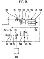
- the refrigerant compressor plant according to the invention is used in a refrigeration system constructed in a known manner, as shown in FIG. 15.
- a line 162 leads from the high pressure port 160, a line 162 to a designated as a whole 164 capacitor.
- From this liquid refrigerant flows in a line 176 to a collector 168 for the liquid refrigerant.
- From the accumulator 168 flows liquid refrigerant via a line 170 to the liquid cooler 120, wherein the main part of the liquid refrigerant flows through the liquid subcooler 20 and flows via a line 172 to an expansion valve 174 for an evaporator 176.
- the vaporized refrigerant flows via a line 178 to the low pressure port 140 of the refrigerant compressor plant according to the invention.
- a small part of the liquid refrigerant is branched off from the line 170 and passed via a line 180 to an injection valve 182, wherein before the injection valve 182 a controllable by a controller 186 solenoid valve 184 is arranged.
- the injection valve 182 constitutes an expansion valve for the liquid cooler 120, which feeds liquid refrigerant via a line 188 to the liquid subcooler 20, which evaporates therein and undercuts the flow of the liquid refrigerant from the line 170 into the line 172, so that in the line 172 supercooled liquid refrigerant flows to the expansion valve 174.
- the vaporized refrigerant from the liquid subcooler 20 is passed via a line 190 to a shown in FIGS. 14 and 15 medium pressure port 192, via which it enters the medium pressure passage 146 and with the coming of the low pressure stage 120 and compressed to medium pressure refrigerant together through the interior 148 of the drive motor 24 flows and then enters the high-pressure stage 110.
- the controller 186 further detects its temperature via a temperature sensor 194 disposed on the motor housing portion 22 of the plant housing 10 and controls the solenoid valve 184 so that the motor housing portion 22, in particular the end wall 150, for example, at a temperature in the range of about 30 ° to about 50 ° Celsius is maintained and thus prevents moisture is condensed in the range of the inverter 16.
- This temperature range is also chosen so that the respective refrigerant has a suitable overheating before entering the high pressure stage 110.
- a controller 200 which controls the drive motor 24 with respect to its speed via the inverter 16 and controls the power of the drive motor 24 according to a measured temperature sensor at the evaporator 176 so that the evaporator 176, the desired cooling capacity is available ,
- a particularly advantageous embodiment of the controller 200 provides that this serves to regulate the temperature of the air flow 206, which is forcibly circulated, for example, in a space to be cooled by means of the blower 204, very precisely to a certain temperature, for example with a control accuracy of 0 , 5 °.
- the controller 200 operates the refrigeration compressor according to the invention in the control range above a minimum cooling power without interruption, that is not as in the prior art, after sufficiently strong cooling off the refrigerant compressor system and wait until the temperature rises again to turn on again but by changing the rotational speed of the drive motor increases or reduces the cooling capacity according to the temperature of the air flow 206.
- the controller 200 is additionally coupled to the controller 186.
- the possibility of switching off the low-pressure stage 120 with the cylinders 122 and 124 is provided with regard to its compressor action.
- a branch 210 is provided in the low-pressure channel 142, with the branch 210, a check valve 212 is connected, which is able to connect the low-pressure channel 142 with the medium-pressure channel 146 when the pressure in the medium-pressure channel 146 under the pressure in the low pressure channel 142 is located.
- a power control valve 214 is still provided, which is capable of the influx of gaseous Refrigerant via the low pressure passage 142 in the low-pressure stage 120 to throttle or block.
- the possibility is given to lower the compressor power of the low-pressure stage 120 so far that the pressure in the medium-pressure passage 146 drops so far that refrigerant flows via the branch 210 from the low-pressure passage 142 via the check valve 112 into the medium-pressure passage 146, the interior 148th flows through the drive motor 24 and then enters the high pressure stage 110 with the cylinders 112 and 114 to be compressed in this to high pressure, wherein the high pressure refrigerant flows through the high pressure passage 154 to the high pressure port 160.
- the controller 200 by switching off the low-pressure stage 120 by the drive motor 24 required power consumption thereby reduce that only the high-pressure stage 110 operates and compresses the refrigerant to a lower pressure, for the necessary cooling capacity is sufficient in this case.
- the drive motor 24 is loaded at the same time less and thus absorbs less power.
- the shutdown of the low-pressure stage 120 by the controller 186 in communication with the controller 200 allows a particularly advantageous exact control of the temperature of the air stream 206, since in the case of a reduction of the cooling capacity first when the low-pressure stage 120 is operating, the speed of the drive motor 24 is reduced by the controller 200 ,
- the shutdown of the low pressure stage 120 has now the advantage that the speed of the drive motor 24 by the controller 200 must not be driven arbitrarily low, but that after switching off the low pressure stage 120, the drive motor 24 can be operated again at a higher speed to the by switching off to compensate for the drop in compressor power entering the low pressure stage 120. In a further reduction then the speed of the drive motor 24 can be lowered again from the higher level.
Landscapes
- Engineering & Computer Science (AREA)
- Mechanical Engineering (AREA)
- General Engineering & Computer Science (AREA)
- Applications Or Details Of Rotary Compressors (AREA)
- Compressors, Vaccum Pumps And Other Relevant Systems (AREA)
- Structures Of Non-Positive Displacement Pumps (AREA)
- Compressor (AREA)
- Compression-Type Refrigeration Machines With Reversible Cycles (AREA)
Applications Claiming Priority (3)
| Application Number | Priority Date | Filing Date | Title |
|---|---|---|---|
| DE19918161A DE19918161A1 (de) | 1999-04-22 | 1999-04-22 | Kältemittelverdichteranlage |
| DE19918161 | 1999-04-22 | ||
| PCT/EP2000/003606 WO2000065232A2 (de) | 1999-04-22 | 2000-04-20 | Kältemittelverdichteranlage |
Publications (3)
| Publication Number | Publication Date |
|---|---|
| EP1105647A2 EP1105647A2 (de) | 2001-06-13 |
| EP1105647B1 EP1105647B1 (de) | 2005-10-19 |
| EP1105647B9 true EP1105647B9 (de) | 2006-03-15 |
Family
ID=7905406
Family Applications (1)
| Application Number | Title | Priority Date | Filing Date |
|---|---|---|---|
| EP00927008A Expired - Lifetime EP1105647B9 (de) | 1999-04-22 | 2000-04-20 | Kältemittelverdichteranlage |
Country Status (7)
| Country | Link |
|---|---|
| US (1) | US6401472B2 (da) |
| EP (1) | EP1105647B9 (da) |
| AT (1) | ATE307290T1 (da) |
| DE (2) | DE19918161A1 (da) |
| DK (1) | DK1105647T3 (da) |
| ES (1) | ES2250129T3 (da) |
| WO (1) | WO2000065232A2 (da) |
Families Citing this family (69)
| Publication number | Priority date | Publication date | Assignee | Title |
|---|---|---|---|---|
| US6047557A (en) * | 1995-06-07 | 2000-04-11 | Copeland Corporation | Adaptive control for a refrigeration system using pulse width modulated duty cycle scroll compressor |
| US6206652B1 (en) | 1998-08-25 | 2001-03-27 | Copeland Corporation | Compressor capacity modulation |
| DE10333402A1 (de) | 2003-07-16 | 2005-02-10 | Bitzer Kühlmaschinenbau Gmbh | Kompressor |
| DE10358471A1 (de) * | 2003-11-17 | 2005-06-23 | Bitzer Kühlmaschinenbau Gmbh | Kältemittelverdichter für Kraftfahrzeuge |
| US20060144408A1 (en) * | 2004-07-23 | 2006-07-06 | Ferry Steven J | Micro-catheter device and method of using same |
| DE102005016433A1 (de) * | 2005-04-05 | 2006-10-12 | Bitzer Kühlmaschinenbau Gmbh | Kältemittelverdichter |
| DE102005029481B4 (de) | 2005-06-24 | 2008-04-10 | Bran + Luebbe Gmbh | Pumpengetriebe |
| DE102005038273A1 (de) * | 2005-08-02 | 2007-02-08 | Linde Ag | Maschine mit einem drehbaren Rotor |
| USD538826S1 (en) | 2005-11-30 | 2007-03-20 | Bitzer Kuehlmaschinenbau Gmbh | Compressor |
| DE102006017301B4 (de) * | 2006-04-12 | 2008-03-06 | Siemens Ag | Pumpe |
| DE102006039782B4 (de) * | 2006-08-24 | 2009-04-09 | Continental Automotive Gmbh | Fluidpumpe, umfassend einen Kurbeltrieb mit ungeteilten Pleueln |
| KR100718567B1 (ko) * | 2006-11-27 | 2007-05-15 | 성주환 | 공기압축기용 바로크랭크축 |
| WO2009001535A1 (ja) | 2007-06-22 | 2008-12-31 | Panasonic Corporation | 冷凍サイクル装置 |
| US8157538B2 (en) | 2007-07-23 | 2012-04-17 | Emerson Climate Technologies, Inc. | Capacity modulation system for compressor and method |
| DE102008045103A1 (de) | 2008-08-29 | 2010-03-11 | TEKO Gesellschaft für Kältetechnik mbH | Hubkolbenverdichter für Kältemittel |
| US20100158712A1 (en) * | 2008-12-23 | 2010-06-24 | New York Air Brake Corporation | Compressor with dual outboard support bearings |
| BRPI1007407A2 (pt) * | 2009-01-27 | 2016-02-16 | Emerson Climate Technologies | sistema e método de descarregamento para um compressor |
| EP2452073B1 (en) * | 2009-07-06 | 2019-05-08 | Carrier Corporation | Bypass unloader valve for compressor capacity control |
| EP2456980B1 (en) * | 2009-07-20 | 2019-06-26 | Carrier Corporation | Suction cutoff unloader valve for compressor capacity control |
| DE102011121926B4 (de) * | 2011-12-22 | 2013-07-18 | Robert Bosch Gmbh | Gerätegehäuse mit Kühlvorrichtung für einströmende Luft |
| CN102606436A (zh) * | 2012-04-09 | 2012-07-25 | 胡传术 | 柱塞泵 |
| ES2929924T3 (es) * | 2012-09-04 | 2022-12-02 | Carrier Corp | Montaje de pies de compresor de refrigeración |
| ITMI20130583A1 (it) * | 2013-04-11 | 2014-10-12 | Frascold S P A | Compressore per un impianto frigorifero e impianto frigorifero comprendente detto compressore |
| BR112018068330B1 (pt) * | 2016-03-14 | 2023-01-17 | Bitzer Kühlmaschinenbau Gmbh | Sistema para entrada em operação para uma unidade de compressor de refrigerante, bem como método para entrada em operação de uma unidade de compressor de refrigerante |
| USD828403S1 (en) * | 2016-08-09 | 2018-09-11 | Gea Refrigeration Germany Gmbh | Compressor |
| USD828402S1 (en) * | 2016-08-09 | 2018-09-11 | Gea Refrigeration Germany Gmbh | Compressor |
| US11624326B2 (en) | 2017-05-21 | 2023-04-11 | Bj Energy Solutions, Llc | Methods and systems for supplying fuel to gas turbine engines |
| USD868841S1 (en) * | 2017-06-27 | 2019-12-03 | Gea Refrigeration Germany Gmbh | Compressor |
| USD865818S1 (en) * | 2017-09-20 | 2019-11-05 | Ateliers Francois, Societe Anonyme | Compressor part |
| WO2019185121A1 (de) * | 2018-03-27 | 2019-10-03 | Bitzer Kühlmaschinenbau Gmbh | Kälteanlage |
| EP3587037B1 (de) | 2018-06-22 | 2023-08-16 | Andreas Stihl AG & Co. KG | Werkzeugkopf für ein handgeführtes arbeitsgerät und arbeitsgerät mit einem werkzeugkopf |
| US11560845B2 (en) | 2019-05-15 | 2023-01-24 | Bj Energy Solutions, Llc | Mobile gas turbine inlet air conditioning system and associated methods |
| CA3092865C (en) | 2019-09-13 | 2023-07-04 | Bj Energy Solutions, Llc | Power sources and transmission networks for auxiliary equipment onboard hydraulic fracturing units and associated methods |
| US10815764B1 (en) | 2019-09-13 | 2020-10-27 | Bj Energy Solutions, Llc | Methods and systems for operating a fleet of pumps |
| US12338772B2 (en) | 2019-09-13 | 2025-06-24 | Bj Energy Solutions, Llc | Systems, assemblies, and methods to enhance intake air flow to a gas turbine engine of a hydraulic fracturing unit |
| CA3191280A1 (en) | 2019-09-13 | 2021-03-13 | Bj Energy Solutions, Llc | Methods and systems for supplying fuel to gas turbine engines |
| CA3092859A1 (en) | 2019-09-13 | 2021-03-13 | Bj Energy Solutions, Llc | Fuel, communications, and power connection systems and related methods |
| US12065968B2 (en) | 2019-09-13 | 2024-08-20 | BJ Energy Solutions, Inc. | Systems and methods for hydraulic fracturing |
| US11015594B2 (en) | 2019-09-13 | 2021-05-25 | Bj Energy Solutions, Llc | Systems and method for use of single mass flywheel alongside torsional vibration damper assembly for single acting reciprocating pump |
| US11555756B2 (en) | 2019-09-13 | 2023-01-17 | Bj Energy Solutions, Llc | Fuel, communications, and power connection systems and related methods |
| US10961914B1 (en) | 2019-09-13 | 2021-03-30 | BJ Energy Solutions, LLC Houston | Turbine engine exhaust duct system and methods for noise dampening and attenuation |
| US11002189B2 (en) | 2019-09-13 | 2021-05-11 | Bj Energy Solutions, Llc | Mobile gas turbine inlet air conditioning system and associated methods |
| CA3092863C (en) | 2019-09-13 | 2023-07-18 | Bj Energy Solutions, Llc | Fuel, communications, and power connection systems and related methods |
| US10895202B1 (en) | 2019-09-13 | 2021-01-19 | Bj Energy Solutions, Llc | Direct drive unit removal system and associated methods |
| CN111022293A (zh) * | 2019-12-18 | 2020-04-17 | 南京久鼎精机冷冻设备有限公司 | 一种以co2作为制冷剂的跨临界往复活塞压缩机 |
| DE102020103975A1 (de) | 2020-02-14 | 2021-08-19 | Bitzer Kühlmaschinenbau Gmbh | Kältemittelverdichter |
| US11708829B2 (en) | 2020-05-12 | 2023-07-25 | Bj Energy Solutions, Llc | Cover for fluid systems and related methods |
| US10968837B1 (en) | 2020-05-14 | 2021-04-06 | Bj Energy Solutions, Llc | Systems and methods utilizing turbine compressor discharge for hydrostatic manifold purge |
| US11428165B2 (en) | 2020-05-15 | 2022-08-30 | Bj Energy Solutions, Llc | Onboard heater of auxiliary systems using exhaust gases and associated methods |
| US11208880B2 (en) | 2020-05-28 | 2021-12-28 | Bj Energy Solutions, Llc | Bi-fuel reciprocating engine to power direct drive turbine fracturing pumps onboard auxiliary systems and related methods |
| US11208953B1 (en) | 2020-06-05 | 2021-12-28 | Bj Energy Solutions, Llc | Systems and methods to enhance intake air flow to a gas turbine engine of a hydraulic fracturing unit |
| US11109508B1 (en) | 2020-06-05 | 2021-08-31 | Bj Energy Solutions, Llc | Enclosure assembly for enhanced cooling of direct drive unit and related methods |
| US11066915B1 (en) | 2020-06-09 | 2021-07-20 | Bj Energy Solutions, Llc | Methods for detection and mitigation of well screen out |
| US10954770B1 (en) | 2020-06-09 | 2021-03-23 | Bj Energy Solutions, Llc | Systems and methods for exchanging fracturing components of a hydraulic fracturing unit |
| US11111768B1 (en) | 2020-06-09 | 2021-09-07 | Bj Energy Solutions, Llc | Drive equipment and methods for mobile fracturing transportation platforms |
| US11028677B1 (en) | 2020-06-22 | 2021-06-08 | Bj Energy Solutions, Llc | Stage profiles for operations of hydraulic systems and associated methods |
| US11939853B2 (en) | 2020-06-22 | 2024-03-26 | Bj Energy Solutions, Llc | Systems and methods providing a configurable staged rate increase function to operate hydraulic fracturing units |
| US11125066B1 (en) | 2020-06-22 | 2021-09-21 | Bj Energy Solutions, Llc | Systems and methods to operate a dual-shaft gas turbine engine for hydraulic fracturing |
| US11933153B2 (en) | 2020-06-22 | 2024-03-19 | Bj Energy Solutions, Llc | Systems and methods to operate hydraulic fracturing units using automatic flow rate and/or pressure control |
| US11473413B2 (en) | 2020-06-23 | 2022-10-18 | Bj Energy Solutions, Llc | Systems and methods to autonomously operate hydraulic fracturing units |
| US11466680B2 (en) | 2020-06-23 | 2022-10-11 | Bj Energy Solutions, Llc | Systems and methods of utilization of a hydraulic fracturing unit profile to operate hydraulic fracturing units |
| US11220895B1 (en) | 2020-06-24 | 2022-01-11 | Bj Energy Solutions, Llc | Automated diagnostics of electronic instrumentation in a system for fracturing a well and associated methods |
| US11149533B1 (en) | 2020-06-24 | 2021-10-19 | Bj Energy Solutions, Llc | Systems to monitor, detect, and/or intervene relative to cavitation and pulsation events during a hydraulic fracturing operation |
| US11193361B1 (en) | 2020-07-17 | 2021-12-07 | Bj Energy Solutions, Llc | Methods, systems, and devices to enhance fracturing fluid delivery to subsurface formations during high-pressure fracturing operations |
| US11639654B2 (en) * | 2021-05-24 | 2023-05-02 | Bj Energy Solutions, Llc | Hydraulic fracturing pumps to enhance flow of fracturing fluid into wellheads and related methods |
| CA3164463A1 (en) | 2021-06-18 | 2022-12-18 | Bj Energy Solutions, Llc | Hydraulic fracturing blender system |
| US12378864B2 (en) | 2021-10-25 | 2025-08-05 | Bj Energy Solutions, Llc | Systems and methods to reduce acoustic resonance or disrupt standing wave formation in a fluid manifold of a high-pressure fracturing system |
| US12196067B1 (en) | 2023-06-16 | 2025-01-14 | Bj Energy Solutions, Llc | Hydraulic fracturing arrangement and blending system |
| DE102023119386A1 (de) * | 2023-07-21 | 2025-01-23 | Viessmann Climate Solutions Se | Kältekreisvorrichtung und wärmepumpe |
Family Cites Families (12)
| Publication number | Priority date | Publication date | Assignee | Title |
|---|---|---|---|---|
| US1716049A (en) * | 1921-01-03 | 1929-06-04 | Cleveland Pneumatic Tool Co | Air tool |
| US2178662A (en) * | 1937-07-24 | 1939-11-07 | Carrier Corp | Fluid compressor |
| US2427638A (en) * | 1944-08-16 | 1947-09-16 | Vilter Mfg Co | Compressor |
| US2454600A (en) * | 1944-10-04 | 1948-11-23 | Air Flo Compressor Company | Compressor |
| US2572711A (en) * | 1945-03-27 | 1951-10-23 | Ruth M Fischer | Air compressor |
| US3663127A (en) * | 1970-11-30 | 1972-05-16 | Tecumseh Products Co | Hermetic compressor oil cooling system |
| US4743176A (en) * | 1986-06-18 | 1988-05-10 | Tecumseh Products Company | Gas flow system for a compressor |
| US5271238A (en) * | 1990-09-14 | 1993-12-21 | Nartron Corporation | Environmental control system |
| JP2875087B2 (ja) * | 1992-01-09 | 1999-03-24 | 株式会社日立製作所 | 冷蔵庫 |
| DE4212162C2 (de) * | 1992-04-10 | 1994-02-17 | Ilka Maschinenfabrik Halle Gmb | Einrichtung zur Kühlung des Elektromotors eines halbhermetischen Kältemittelverdichters |
| DK172128B1 (da) * | 1995-07-06 | 1997-11-17 | Danfoss As | Kompressor med styreelektronik |
| DE19726943C2 (de) * | 1997-06-25 | 2000-03-23 | Bitzer Kuehlmaschinenbau Gmbh | Kältemittelkompressor |
-
1999
- 1999-04-22 DE DE19918161A patent/DE19918161A1/de not_active Ceased
-
2000
- 2000-04-20 ES ES00927008T patent/ES2250129T3/es not_active Expired - Lifetime
- 2000-04-20 AT AT00927008T patent/ATE307290T1/de not_active IP Right Cessation
- 2000-04-20 DE DE50011365T patent/DE50011365D1/de not_active Expired - Lifetime
- 2000-04-20 EP EP00927008A patent/EP1105647B9/de not_active Expired - Lifetime
- 2000-04-20 DK DK00927008T patent/DK1105647T3/da active
- 2000-04-20 WO PCT/EP2000/003606 patent/WO2000065232A2/de not_active Ceased
- 2000-12-21 US US09/747,356 patent/US6401472B2/en not_active Expired - Lifetime
Also Published As
| Publication number | Publication date |
|---|---|
| DE50011365D1 (de) | 2005-11-24 |
| US20010011463A1 (en) | 2001-08-09 |
| DE19918161A1 (de) | 2000-11-02 |
| ATE307290T1 (de) | 2005-11-15 |
| EP1105647B1 (de) | 2005-10-19 |
| WO2000065232A3 (de) | 2001-03-22 |
| DK1105647T3 (da) | 2006-02-13 |
| EP1105647A2 (de) | 2001-06-13 |
| ES2250129T3 (es) | 2006-04-16 |
| US6401472B2 (en) | 2002-06-11 |
| WO2000065232A2 (de) | 2000-11-02 |
Similar Documents
| Publication | Publication Date | Title |
|---|---|---|
| EP1105647B9 (de) | Kältemittelverdichteranlage | |
| EP1036276B1 (de) | Schraubenverdichter | |
| DE4203677C2 (de) | Spiralverdichter | |
| DE4229069C2 (de) | Taumelscheiben-Kältemittelkompressor für ein Kühlsystem | |
| DE3641226C2 (da) | ||
| EP1444441A1 (de) | Temperierugsverfahren einer schraubenvakuumpumpe | |
| EP3775716B1 (de) | Kälteanlage | |
| WO2009030536A1 (de) | Kältemittelkompressor | |
| DE102007004130B4 (de) | Taumelscheiben-Verstellkompressor mit variablem Drosselmechanismus zwischen Taumelscheibenkammer und einem Bereich niedrigen Drucks | |
| DE2852896A1 (de) | Kompressor-expander-einheit | |
| DE19708428C2 (de) | Kälteanlage | |
| WO2015071128A1 (de) | Kühlkreislauf | |
| DE3426190A1 (de) | Anordnung zum beeinflussen der drehzahl eines kompressors einer kaelteanlage | |
| EP0180904A2 (de) | Kühlvorrichtung | |
| WO2017148930A1 (de) | Elektromotor, wärmepumpe mit dem elektromotor, verfahren zum herstellen des elektromotors und verfahren zum betreiben des elektromotors | |
| DE102020213544B4 (de) | Gaskältemaschine, Verfahren zum Betreiben einer Gaskältemaschine und Verfahren zum Herstellen einer Gaskältemaschine mit einem Rekuperator um den Ansaugbereich | |
| EP2022990B1 (de) | Werkzeugmaschine und Versorgungsaggregat | |
| EP4269796A1 (de) | Hubkolbenverdichter für kältemittel | |
| DE60210691T2 (de) | Hermetischer Verdichter | |
| DE10232100A1 (de) | Ölfreier Kompressor | |
| DE2405300A1 (de) | Dampfverdichtungs- und kuehlverfahren sowie kuehlanlage zur durchfuehrung des verfahrens | |
| EP3499039B1 (de) | Schraubenvakuumpumpe | |
| DE102024120153B4 (de) | Hubkolbenverdichter für eine Wärmepumpe mit einem integrierten Antriebsmotor, Kältemittelkreislauf mit Hubkolbenverdichter und Wärmepumpe | |
| DE102020213822B4 (de) | Gaskältemaschine, Verfahren zum Betreiben einer Gaskältemaschine und Verfahren zum Herstellen einer Gaskältemaschine als offenes System | |
| DE102020213554B4 (de) | Gaskältemaschine, Verfahren zum Betreiben einer Gaskältemaschine und Verfahren zum Herstellen einer Gaskältemaschine mit einer gekühlten Elektronik |
Legal Events
| Date | Code | Title | Description |
|---|---|---|---|
| PUAI | Public reference made under article 153(3) epc to a published international application that has entered the european phase |
Free format text: ORIGINAL CODE: 0009012 |
|
| 17P | Request for examination filed |
Effective date: 20001213 |
|
| AK | Designated contracting states |
Kind code of ref document: A2 Designated state(s): AT BE CH CY DE DK ES FI FR GB GR IE IT LI LU MC NL PT SE |
|
| AX | Request for extension of the european patent |
Free format text: AL;LT;LV;MK;RO;SI |
|
| 17Q | First examination report despatched |
Effective date: 20040830 |
|
| GRAP | Despatch of communication of intention to grant a patent |
Free format text: ORIGINAL CODE: EPIDOSNIGR1 |
|
| GRAS | Grant fee paid |
Free format text: ORIGINAL CODE: EPIDOSNIGR3 |
|
| GRAA | (expected) grant |
Free format text: ORIGINAL CODE: 0009210 |
|
| AK | Designated contracting states |
Kind code of ref document: B1 Designated state(s): AT BE CH CY DE DK ES FI FR GB GR IE IT LI LU MC NL PT SE |
|
| REG | Reference to a national code |
Ref country code: GB Ref legal event code: FG4D Free format text: NOT ENGLISH |
|
| REG | Reference to a national code |
Ref country code: CH Ref legal event code: EP |
|
| REG | Reference to a national code |
Ref country code: IE Ref legal event code: FG4D Free format text: LANGUAGE OF EP DOCUMENT: GERMAN |
|
| REF | Corresponds to: |
Ref document number: 50011365 Country of ref document: DE Date of ref document: 20051124 Kind code of ref document: P |
|
| REG | Reference to a national code |
Ref country code: CH Ref legal event code: NV Representative=s name: KIRKER & CIE SA |
|
| REG | Reference to a national code |
Ref country code: SE Ref legal event code: TRGR |
|
| REG | Reference to a national code |
Ref country code: DK Ref legal event code: T3 |
|
| GBT | Gb: translation of ep patent filed (gb section 77(6)(a)/1977) |
Effective date: 20060125 |
|
| REG | Reference to a national code |
Ref country code: GR Ref legal event code: EP Ref document number: 20050403893 Country of ref document: GR |
|
| REG | Reference to a national code |
Ref country code: ES Ref legal event code: FG2A Ref document number: 2250129 Country of ref document: ES Kind code of ref document: T3 |
|
| PG25 | Lapsed in a contracting state [announced via postgrant information from national office to epo] |
Ref country code: MC Free format text: LAPSE BECAUSE OF NON-PAYMENT OF DUE FEES Effective date: 20060430 |
|
| ET | Fr: translation filed | ||
| PLBE | No opposition filed within time limit |
Free format text: ORIGINAL CODE: 0009261 |
|
| STAA | Information on the status of an ep patent application or granted ep patent |
Free format text: STATUS: NO OPPOSITION FILED WITHIN TIME LIMIT |
|
| 26N | No opposition filed |
Effective date: 20060720 |
|
| PGFP | Annual fee paid to national office [announced via postgrant information from national office to epo] |
Ref country code: PT Payment date: 20080115 Year of fee payment: 9 |
|
| PGFP | Annual fee paid to national office [announced via postgrant information from national office to epo] |
Ref country code: CH Payment date: 20080429 Year of fee payment: 9 Ref country code: LU Payment date: 20080414 Year of fee payment: 9 |
|
| PGFP | Annual fee paid to national office [announced via postgrant information from national office to epo] |
Ref country code: AT Payment date: 20080208 Year of fee payment: 9 Ref country code: BE Payment date: 20080205 Year of fee payment: 9 |
|
| PGFP | Annual fee paid to national office [announced via postgrant information from national office to epo] |
Ref country code: FI Payment date: 20080411 Year of fee payment: 9 Ref country code: CY Payment date: 20080121 Year of fee payment: 9 |
|
| PGFP | Annual fee paid to national office [announced via postgrant information from national office to epo] |
Ref country code: NL Payment date: 20080430 Year of fee payment: 9 Ref country code: SE Payment date: 20080414 Year of fee payment: 9 |
|
| PGFP | Annual fee paid to national office [announced via postgrant information from national office to epo] |
Ref country code: GR Payment date: 20080118 Year of fee payment: 9 |
|
| PGFP | Annual fee paid to national office [announced via postgrant information from national office to epo] |
Ref country code: DK Payment date: 20090415 Year of fee payment: 10 Ref country code: IE Payment date: 20090428 Year of fee payment: 10 |
|
| REG | Reference to a national code |
Ref country code: PT Ref legal event code: MM4A Free format text: LAPSE DUE TO NON-PAYMENT OF FEES Effective date: 20091020 |
|
| BERE | Be: lapsed |
Owner name: *BITZER KUHLMASCHINENBAU G.M.B.H. Effective date: 20090430 |
|
| REG | Reference to a national code |
Ref country code: CH Ref legal event code: PL |
|
| EUG | Se: european patent has lapsed | ||
| NLV4 | Nl: lapsed or anulled due to non-payment of the annual fee |
Effective date: 20091101 |
|
| PG25 | Lapsed in a contracting state [announced via postgrant information from national office to epo] |
Ref country code: CH Free format text: LAPSE BECAUSE OF NON-PAYMENT OF DUE FEES Effective date: 20090430 Ref country code: AT Free format text: LAPSE BECAUSE OF NON-PAYMENT OF DUE FEES Effective date: 20090420 Ref country code: LI Free format text: LAPSE BECAUSE OF NON-PAYMENT OF DUE FEES Effective date: 20090430 Ref country code: FI Free format text: LAPSE BECAUSE OF NON-PAYMENT OF DUE FEES Effective date: 20090420 |
|
| PG25 | Lapsed in a contracting state [announced via postgrant information from national office to epo] |
Ref country code: NL Free format text: LAPSE BECAUSE OF NON-PAYMENT OF DUE FEES Effective date: 20091101 |
|
| PG25 | Lapsed in a contracting state [announced via postgrant information from national office to epo] |
Ref country code: CY Free format text: LAPSE BECAUSE OF NON-PAYMENT OF DUE FEES Effective date: 20090420 Ref country code: PT Free format text: LAPSE BECAUSE OF NON-PAYMENT OF DUE FEES Effective date: 20091020 |
|
| PG25 | Lapsed in a contracting state [announced via postgrant information from national office to epo] |
Ref country code: BE Free format text: LAPSE BECAUSE OF NON-PAYMENT OF DUE FEES Effective date: 20090430 |
|
| PG25 | Lapsed in a contracting state [announced via postgrant information from national office to epo] |
Ref country code: GR Free format text: LAPSE BECAUSE OF NON-PAYMENT OF DUE FEES Effective date: 20091104 |
|
| REG | Reference to a national code |
Ref country code: DK Ref legal event code: EBP |
|
| REG | Reference to a national code |
Ref country code: IE Ref legal event code: MM4A |
|
| PG25 | Lapsed in a contracting state [announced via postgrant information from national office to epo] |
Ref country code: IE Free format text: LAPSE BECAUSE OF NON-PAYMENT OF DUE FEES Effective date: 20100420 |
|
| PG25 | Lapsed in a contracting state [announced via postgrant information from national office to epo] |
Ref country code: LU Free format text: LAPSE BECAUSE OF NON-PAYMENT OF DUE FEES Effective date: 20090420 Ref country code: DK Free format text: LAPSE BECAUSE OF NON-PAYMENT OF DUE FEES Effective date: 20100503 |
|
| PG25 | Lapsed in a contracting state [announced via postgrant information from national office to epo] |
Ref country code: SE Free format text: LAPSE BECAUSE OF NON-PAYMENT OF DUE FEES Effective date: 20090421 |
|
| REG | Reference to a national code |
Ref country code: DE Ref legal event code: R082 Ref document number: 50011365 Country of ref document: DE Representative=s name: HOEGER, STELLRECHT & PARTNER PATENTANWAELTE MB, DE |
|
| REG | Reference to a national code |
Ref country code: FR Ref legal event code: PLFP Year of fee payment: 17 |
|
| REG | Reference to a national code |
Ref country code: FR Ref legal event code: PLFP Year of fee payment: 18 |
|
| REG | Reference to a national code |
Ref country code: FR Ref legal event code: PLFP Year of fee payment: 19 |
|
| REG | Reference to a national code |
Ref country code: DE Ref legal event code: R082 Ref document number: 50011365 Country of ref document: DE Representative=s name: HOEGER, STELLRECHT & PARTNER PATENTANWAELTE MB, DE |
|
| PGFP | Annual fee paid to national office [announced via postgrant information from national office to epo] |
Ref country code: IT Payment date: 20190419 Year of fee payment: 20 Ref country code: ES Payment date: 20190524 Year of fee payment: 20 Ref country code: DE Payment date: 20190621 Year of fee payment: 20 |
|
| PGFP | Annual fee paid to national office [announced via postgrant information from national office to epo] |
Ref country code: FR Payment date: 20190426 Year of fee payment: 20 |
|
| PGFP | Annual fee paid to national office [announced via postgrant information from national office to epo] |
Ref country code: GB Payment date: 20190429 Year of fee payment: 20 |
|
| REG | Reference to a national code |
Ref country code: DE Ref legal event code: R071 Ref document number: 50011365 Country of ref document: DE |
|
| REG | Reference to a national code |
Ref country code: GB Ref legal event code: PE20 Expiry date: 20200419 |
|
| PG25 | Lapsed in a contracting state [announced via postgrant information from national office to epo] |
Ref country code: GB Free format text: LAPSE BECAUSE OF EXPIRATION OF PROTECTION Effective date: 20200419 |
|
| REG | Reference to a national code |
Ref country code: ES Ref legal event code: FD2A Effective date: 20200902 |
|
| PG25 | Lapsed in a contracting state [announced via postgrant information from national office to epo] |
Ref country code: ES Free format text: LAPSE BECAUSE OF EXPIRATION OF PROTECTION Effective date: 20200421 |