EP1105653B1 - Fixation filetee - Google Patents
Fixation filetee Download PDFInfo
- Publication number
- EP1105653B1 EP1105653B1 EP99940391A EP99940391A EP1105653B1 EP 1105653 B1 EP1105653 B1 EP 1105653B1 EP 99940391 A EP99940391 A EP 99940391A EP 99940391 A EP99940391 A EP 99940391A EP 1105653 B1 EP1105653 B1 EP 1105653B1
- Authority
- EP
- European Patent Office
- Prior art keywords
- fastener
- shank
- head
- workpiece
- bore
- Prior art date
- Legal status (The legal status is an assumption and is not a legal conclusion. Google has not performed a legal analysis and makes no representation as to the accuracy of the status listed.)
- Expired - Lifetime
Links
- 230000001419 dependent effect Effects 0.000 claims 1
- 239000000463 material Substances 0.000 description 6
- 238000009434 installation Methods 0.000 description 5
- 239000004033 plastic Substances 0.000 description 3
- 229920003023 plastic Polymers 0.000 description 3
- 229920001343 polytetrafluoroethylene Polymers 0.000 description 2
- 239000004810 polytetrafluoroethylene Substances 0.000 description 2
- 230000000750 progressive effect Effects 0.000 description 2
- 229910000838 Al alloy Inorganic materials 0.000 description 1
- FYYHWMGAXLPEAU-UHFFFAOYSA-N Magnesium Chemical compound [Mg] FYYHWMGAXLPEAU-UHFFFAOYSA-N 0.000 description 1
- 238000013459 approach Methods 0.000 description 1
- 230000000295 complement effect Effects 0.000 description 1
- 230000008602 contraction Effects 0.000 description 1
- 238000007689 inspection Methods 0.000 description 1
- 229910052749 magnesium Inorganic materials 0.000 description 1
- 239000011777 magnesium Substances 0.000 description 1
- 239000002923 metal particle Substances 0.000 description 1
- -1 polytetrafluoroethylene Polymers 0.000 description 1
- 239000012858 resilient material Substances 0.000 description 1
- 238000004904 shortening Methods 0.000 description 1
- 239000007779 soft material Substances 0.000 description 1
Images



Classifications
-
- F—MECHANICAL ENGINEERING; LIGHTING; HEATING; WEAPONS; BLASTING
- F16—ENGINEERING ELEMENTS AND UNITS; GENERAL MEASURES FOR PRODUCING AND MAINTAINING EFFECTIVE FUNCTIONING OF MACHINES OR INSTALLATIONS; THERMAL INSULATION IN GENERAL
- F16B—DEVICES FOR FASTENING OR SECURING CONSTRUCTIONAL ELEMENTS OR MACHINE PARTS TOGETHER, e.g. NAILS, BOLTS, CIRCLIPS, CLAMPS, CLIPS OR WEDGES; JOINTS OR JOINTING
- F16B19/00—Bolts without screw-thread; Pins, including deformable elements; Rivets
- F16B19/04—Rivets; Spigots or the like fastened by riveting
- F16B19/08—Hollow rivets; Multi-part rivets
- F16B19/10—Hollow rivets; Multi-part rivets fastened by expanding mechanically
Definitions
- the invention relates to a threaded fastener of the type comprising:
- Such a fastener is hereinafter referred to as "a fastener of the type defined".
- a fastener of the type defined An example of such a fastener is commercially available and well known under the Registered Trade Mark RIVSCREW, and is described in GB 2 140 891 A, to which the reader is referred for a fuller description.
- the present invention provides, in one of its aspects, a fastener of the type defined in which the expandable part of the shank is provided with a plurality of radially extending lugs or other protrusions thereby to resist unscrewing of the fastener from the workpiece.
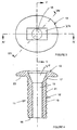
- the fastener 11 of this example is made of aluminium alloy having typically 2.5% magnesium (e.g. type 5052) and is about 8 mm overall length. It comprises a shank 12 of generally cylindrical symmetry, a radially enlarged head 13 at one end of the shank, an external screw thread 14 extending along the major part of the length of the shank, and a bore 15 extending completely through the head and shank.
- the thread 14 extends from the tail end 16 (i.e. the end remote from the head 13) along the majority of length of the shank 12, but stops short of a tapering radially enlarged part 17 of the shank adjacent the head 13.
- the thread 14 consists of a single-start groove 18 of vee-section (shown in Figure 8) and a flat-topped crest 19 which is about twice as wide as the groove 18.
- the threaded part of the fastener shank 12 is provided with a large number of radially extending lugs 21. These lugs are located in the trough of the groove 18 of the thread and protrude radially outwardly above the crest. Each lug extends completely across the width of the groove trough and has a curved top edge, above the thread crest 19, and has two substantially flat opposite faces, facing in opposite directions, each face being at right angles to the direction substantially tangential to the shank.
- the radial extent of protrusion of the lugs is somewhat exaggerated for clarity of illustration.
- the lugs are arranged in four rows 22, each row extending along the shank in a direction substantially parallel to the axis of the shank, the rows being spaced apart by 90° around the circumference of the shank so that there are two sets of two rows, the two rows in each set being diametrically opposite each other.
- the head 13 is of substantially oval or elliptical shape, as illustrated in Figures 2 and 3, the longer diameter (on the line IV-IV of Figure 3) being about 1.2 times the shorter diameter (on the line V-V of Figure 30.
- the head is of conventional "pan head" profile, and has a flat underface 23.
- the head 13 is provided with a wrenching recess for co-operation with a suitable wrenching tool or driver to rotate an installed fastener to unscrew it.
- the recess is in the form of a generally rectangular-section slot 24.
- the slot is co-axial with the bore 15, and has its longer and shorter axes respectively coinciding with the longer and shorter axes of the head 13, as illustrated in Figure 3.
- Figure 6 shows the fastener inserted in a workpiece, ready for installation.
- a number of fasteners are loaded on a mandrel 25 which has a tapering enlarged head 26, larger than the fastener shank bore 15, which is pulled through each fastener in turn in order to radially expand its shank.
- the mandrel 25 forms part of an installation tool (not shown) of well-known type, which includes an annular nosepiece 27 (provided by separable jaw-members to enable each fastener to be fed through it in turn).
- the fastener is used to secure a relatively thin workpiece member 28 to a thicker member 29 which is of plastics material, e.g. PTFE (polytetrafluoroethylene).
- PTFE polytetrafluoroethylene
- the member 29 is provided with a bore 31 in which the fastener shank 12 including the projecting lugs 21 is a clearance fit.
- the thinner member 28 is formed with a circular hole 32 which in current workshop assembly practice will be rather larger in diameter than the bore 31 in order to assist in relative alignment of the hole and bore.
- the hole 32 is thus large enough to accommodate the widest part of the tapering fastener underhead enlargement 17.
- the shank 12 of the fastener on the mandrel 25 is inserted through the hole 32 and into the bore 31 until the underface 23 of the head 13 contacts the near face of the near workpiece 28.
- the installation tool is pushed so that the nosepiece 27 presses the fastener head underface 13 against the workpiece 28 and so pushes the workpiece 28 into contact with the workpiece 29, closing any gap between them.
- the tool is then actuated to withdraw the mandrel 25 progressively into the nosepiece 27.
- the mandrel head 26 is thus drawn through the bore 15 of the fastener, progressively radially expanding the shank from the tail end towards the head end, the reaction to the pulling force being taken through the nosepiece 27 against the fastener head 13.
- the embedding of the lugs 21 in the workpiece bore wall provides substantially positive resistance to rotation of the installed fastener, i.e. a high "torque to turn" figure.
- it has been found desirable to configure the wrenching recess 24 and its relationship to the head so that the recess walls, and the adjacent parts of the head and shank, can support the substantial forces generated when rotating the installed fastener by means of a suitable wrenching tool having a blade or spigot which is complementary in shape to the fastener head recess 24.
- the tapering shape of the recess and tool assist in keeping the tool in engagement with the recess when the tool is in use.
- the initial resistance to rotation is also assisted by the high compressive forces, and hence frictional forces, between the underhead face 23 and the outer face of the workpiece 28. If the outer workpiece 28 is sufficiently soft or resilient, the underhead face 23 may embed itself to some extent in the workpiece 28, when its non-circular shape adds still further to the resistance to turning.
- the fastener continues to offer a high resistance to the remainder of the unscrewing operation (i.e. a high prevailing torque). It has been found from inspection of unscrewed fasteners that the projecting parts of the lugs 21 may have been deformed or bent so that they no longer project above the crest of the thread. However, they remain attached to the shank of the fastener, rather than becoming detached from it. This helps to prevent the generation of swarf or undesired metal particles at the site, which is an important practical requirement by users of such fasteners.
- the lugs also increase the axial pull-out force.
- the radially extending lugs or protrusions could take any other convenient form, and could be arranged on the fastener shank in any other convenient way.
- a hexagonal bore could be formed in the fastener during installation, by the use of a hexagonal-headed mandrel, as is described in GB 2 140 891 A.
- the thread could be multi-start.
- the form of the thread could be other than as illustrated in the foregoing example.
- the pitch angle of the thread could be much greater, up to a single-turn helix extending the whole length of the shank.
Landscapes
- Engineering & Computer Science (AREA)
- General Engineering & Computer Science (AREA)
- Mechanical Engineering (AREA)
- Dowels (AREA)
- Connection Of Plates (AREA)
Claims (14)
- Elément de fixation fileté du type comprenant :caractérisé en ce que la partie extensible de la tige (12) est munie d'une pluralité de pattes s'étendant radialement (21) ou d'autres saillies destinées à résister ainsi au dévissage de l'élément de fixation de l'alésage de la pièce de travail.une tige (12),une tête radialement élargie (13) à une extrémité de la tige,un filet de vis externe (14) sur au moins une partie de la tige (12),et un alésage (15) s'étendant à travers la tête (13) et dans la partie filetée de la tige (12),au moins la partie filetée de la tige (12) étant radialement extensible pour entrer en prise par filetage avec la paroi d'un alésage non fileté approprié dans une pièce de travail dans laquelle la partie filetée a été insérée, l'élément de fixation pouvant être ensuite retiré en le dévissant de l'alésage de la pièce de travail;
- Elément de fixation selon la revendication 1, dans lequel les saillies sont situées sur la partie filetée de la tige (12).
- Elément de fixation selon la revendication 2, dans lequel chaque saillie s'étend vers l'extérieur depuis une position dans le fond du filet sur la tige (12).
- Elément de fixation selon la revendication 2 ou la revendication 3, dans lequel chaque saillie s'étend radialement vers l'extérieur au-delà de la crête du filet sur la tige (12).
- Elément de fixation selon l'une quelconque des revendications précédentes, dans lequel les saillies sont disposées en au moins une rangée (22) s'étendant sensiblement parallèlement à l'axe de la tige (12).
- Elément de fixation selon la revendication 5, dans lequel les saillies sont disposées en une pluralité de ces rangées (22).
- Elément de fixation selon l'une quelconque des revendications précédentes, dans lequel les saillies sont disposées à des positions sensiblement diamétralement opposées les unes des autres autour de l'axe de la tige (12).
- Elément de fixation selon la revendication 3, dans lequel la partie d'une saillie qui se trouve dans le fond s'étend complètement à travers la largeur du fond.
- Elément de fixation selon l'une quelconque des revendications précédentes, dans lequel au moins cette partie de la tête radialement élargie (13) qui, pendant l'utilisation de l'élément de fixation, bute contre la partie de la pièce de travail entourant l'alésage, présente une forme non circulaire, pour aider ainsi à résister à une rotation de dévissage de l'élément de fixation installé par rapport à la pièce de travail, si la tête d'élément de fixation est suffisamment encastrée dans la pièce de travail.
- Elément de fixation selon la revendication 9, dans lequel au moins ladite partie de la tête d'élément de fixation présente une forme plus longue selon une dimension transversale que selon la direction transversale perpendiculaire à celle-ci.
- Elément de fixation selon la revendication 10, dans lequel au moins ladite partie de la tête d'élément de fixation (13) présente une forme sensiblement ovale ou elliptique.
- Elément de fixation selon l'une quelconque des revendications précédentes, dans lequel la tête d'élément de fixation (13) est munie d'une fente, ou d'un autre évidement, qui est allongée à travers la tête de façon à créer des surfaces d'entraínement destinées à coopérer avec un outil approprié pour dévisser un élément de fixation installé.
- Elément de fixation selon la revendication 12, lorsqu'elle dépend de la revendication 10, dans lequel l'évidement d'entraínement est allongé dans la même direction que la dimension transversale plus longue de ladite partie de la tête.
- Elément de fixation selon la revendication 12 ou la revendication 13, dans lequel la partie de la tige d'élément de fixation (12) adjacente à la tête est radialement élargie, pour ainsi renforcer la partie de l'élément de fixation adjacente à l'évidement d'entraínement.
Applications Claiming Priority (3)
| Application Number | Priority Date | Filing Date | Title |
|---|---|---|---|
| GB9818255 | 1998-08-21 | ||
| GB9818255A GB2340908A (en) | 1998-08-21 | 1998-08-21 | Expandable screw-threaded fastener |
| PCT/GB1999/002776 WO2000011355A1 (fr) | 1998-08-21 | 1999-08-23 | Fixation filetee |
Publications (2)
| Publication Number | Publication Date |
|---|---|
| EP1105653A1 EP1105653A1 (fr) | 2001-06-13 |
| EP1105653B1 true EP1105653B1 (fr) | 2002-07-24 |
Family
ID=10837618
Family Applications (1)
| Application Number | Title | Priority Date | Filing Date |
|---|---|---|---|
| EP99940391A Expired - Lifetime EP1105653B1 (fr) | 1998-08-21 | 1999-08-23 | Fixation filetee |
Country Status (6)
| Country | Link |
|---|---|
| US (1) | US6447227B1 (fr) |
| EP (1) | EP1105653B1 (fr) |
| AU (1) | AU5437699A (fr) |
| DE (1) | DE69902280T2 (fr) |
| GB (1) | GB2340908A (fr) |
| WO (1) | WO2000011355A1 (fr) |
Families Citing this family (14)
| Publication number | Priority date | Publication date | Assignee | Title |
|---|---|---|---|---|
| US7793989B2 (en) * | 2004-07-14 | 2010-09-14 | Pinckney Jr Robert | Locking connector with depressions |
| US7506901B2 (en) * | 2004-07-14 | 2009-03-24 | Robert Pinckney | Resilient locking connection |
| JP4926953B2 (ja) * | 2005-05-31 | 2012-05-09 | 株式会社トープラ | タッピングねじ |
| TWM284777U (en) * | 2005-08-09 | 2006-01-01 | Tqc Fasteners Ind Corp | Improved structure of anti-disengaging screw |
| BRPI0910325A8 (pt) | 2008-04-05 | 2019-01-29 | Synthes Gmbh | implante intervertebral expansível |
| EP2451373B1 (fr) | 2009-07-06 | 2017-06-07 | Synthes GmbH | Ensembles fixation extensible |
| DE202010015839U1 (de) * | 2010-11-26 | 2011-02-24 | Acument Gmbh & Co. Ohg | Selbstsicherndes Gewinde |
| JP5653824B2 (ja) * | 2011-04-05 | 2015-01-14 | イワタボルト株式会社 | アースボルト |
| KR102214840B1 (ko) * | 2014-05-02 | 2021-02-10 | 엘지전자 주식회사 | 압축기 및 스크롤 압축기 |
| US10940016B2 (en) | 2017-07-05 | 2021-03-09 | Medos International Sarl | Expandable intervertebral fusion cage |
| US11174969B2 (en) * | 2019-01-16 | 2021-11-16 | The Boeing Company | Threaded connection of a duct |
| CN109973501A (zh) * | 2019-03-13 | 2019-07-05 | 杭州钜力锚杆科技有限公司 | 一种可拆卸分体式螺母 |
| JP6626231B1 (ja) * | 2019-05-21 | 2019-12-25 | 株式会社トープラ | おねじ部材 |
| DE202019104970U1 (de) * | 2019-09-09 | 2020-12-10 | Böllhoff Verbindungstechnik GmbH | Kugelbolzen |
Family Cites Families (11)
| Publication number | Priority date | Publication date | Assignee | Title |
|---|---|---|---|---|
| GB640451A (en) * | 1946-09-02 | 1950-07-19 | Aviat Developments Ltd | Improvements in or relating to tubular fastening devices or bushes |
| US3220454A (en) * | 1963-11-26 | 1965-11-30 | Neuschotz Robert | Threaded insert having expandable serrated locking portion |
| US3319690A (en) * | 1964-01-02 | 1967-05-16 | Rosan Eng Corp | Top driven locking insert |
| US3230994A (en) * | 1964-08-10 | 1966-01-25 | Rosan Eng Corp | Insert having an expandable split locking collar and method of using same |
| US4273175A (en) * | 1979-04-04 | 1981-06-16 | The Lamson & Sessions Co. | Thread convolution |
| GB8315077D0 (en) * | 1983-06-01 | 1983-07-06 | Avdel Ltd | Threaded fastener |
| GB2140891B (en) * | 1983-06-01 | 1986-11-19 | Avdel Ltd | Swaged-in threaded fastener |
| US5011352A (en) * | 1989-09-08 | 1991-04-30 | Hi-Shear Corporation | Deflection type thread lock for a threaded fastener |
| US5156507A (en) * | 1991-04-29 | 1992-10-20 | Northwest Design Products | Expansible fastening device |
| DE19543651C2 (de) * | 1995-11-23 | 1999-06-02 | Brose Fahrzeugteile | Spreizbares Befestigungselement zum Befestigen oder Verbinden von Teilen |
| DE19646668A1 (de) * | 1996-11-12 | 1998-05-14 | Sfs Ind Holding Ag | In ein Sackloch einsetzbares Befestigungselement |
-
1998
- 1998-08-21 GB GB9818255A patent/GB2340908A/en not_active Withdrawn
-
1999
- 1999-08-23 DE DE69902280T patent/DE69902280T2/de not_active Expired - Fee Related
- 1999-08-23 WO PCT/GB1999/002776 patent/WO2000011355A1/fr not_active Ceased
- 1999-08-23 EP EP99940391A patent/EP1105653B1/fr not_active Expired - Lifetime
- 1999-08-23 US US09/762,157 patent/US6447227B1/en not_active Expired - Fee Related
- 1999-08-23 AU AU54376/99A patent/AU5437699A/en not_active Abandoned
Also Published As
| Publication number | Publication date |
|---|---|
| DE69902280D1 (de) | 2002-08-29 |
| DE69902280T2 (de) | 2003-02-27 |
| WO2000011355A1 (fr) | 2000-03-02 |
| US6447227B1 (en) | 2002-09-10 |
| GB9818255D0 (en) | 1998-10-14 |
| AU5437699A (en) | 2000-03-14 |
| EP1105653A1 (fr) | 2001-06-13 |
| GB2340908A (en) | 2000-03-01 |
Similar Documents
| Publication | Publication Date | Title |
|---|---|---|
| US6447227B1 (en) | Threaded fastener | |
| KR100752102B1 (ko) | 고강도 블라인드 볼트 | |
| US8496421B1 (en) | Ferrule lock nuts | |
| CN100387399C (zh) | 单面紧固件和用于单面紧固件安装的凸头组件 | |
| CA2494180C (fr) | Procede et element de fixation d'aide au taraudage | |
| RU2357115C2 (ru) | Спиральный приводной крепежный элемент с фрикционными зацепляемыми поверхностями | |
| US20020192047A1 (en) | Blind rivet nut and fastening unit | |
| US3820579A (en) | Blind stud fastener | |
| JP2010249321A (ja) | ネジ山付留め具のための渦巻型駆動システム | |
| GB2113791A (en) | Blind fastener and method and apparatus for making same | |
| KR20020054330A (ko) | 블라인드 패스너 및 구동 너트 조립체 | |
| US6835036B2 (en) | Concrete anchor | |
| EP0674109B1 (fr) | Ecrou-insert et élément de fixation | |
| EP0450820A1 (fr) | Elément de fixation | |
| US5743690A (en) | Self-locking tubular fastener and fastener system | |
| EP4158210B1 (fr) | Élément de fixation à plusieurs pièces comprenant une partie filetée effilée et procédé de fixation | |
| EP0677668B1 (fr) | Améliorations se rapportant aux éléments de fixation | |
| WO1996041083A1 (fr) | Systeme de fixation a verrouillage deformable et son procede d'utilisation | |
| CA3063068A1 (fr) | Dispositif de fixation | |
| HK1094719A (en) | A fastening element and method of forming a fastener assembly using said fastening element | |
| HK1008436B (en) | Improvements relating to fasteners |
Legal Events
| Date | Code | Title | Description |
|---|---|---|---|
| PUAI | Public reference made under article 153(3) epc to a published international application that has entered the european phase |
Free format text: ORIGINAL CODE: 0009012 |
|
| 17P | Request for examination filed |
Effective date: 20010206 |
|
| AK | Designated contracting states |
Kind code of ref document: A1 Designated state(s): AT BE CH CY DE DK ES FI FR GB GR IE IT LI LU MC NL PT SE |
|
| GRAG | Despatch of communication of intention to grant |
Free format text: ORIGINAL CODE: EPIDOS AGRA |
|
| 17Q | First examination report despatched |
Effective date: 20011024 |
|
| GRAG | Despatch of communication of intention to grant |
Free format text: ORIGINAL CODE: EPIDOS AGRA |
|
| GRAH | Despatch of communication of intention to grant a patent |
Free format text: ORIGINAL CODE: EPIDOS IGRA |
|
| GRAH | Despatch of communication of intention to grant a patent |
Free format text: ORIGINAL CODE: EPIDOS IGRA |
|
| GRAA | (expected) grant |
Free format text: ORIGINAL CODE: 0009210 |
|
| AK | Designated contracting states |
Kind code of ref document: B1 Designated state(s): DE FR GB IT |
|
| REG | Reference to a national code |
Ref country code: GB Ref legal event code: FG4D |
|
| REG | Reference to a national code |
Ref country code: IE Ref legal event code: FG4D |
|
| REF | Corresponds to: |
Ref document number: 69902280 Country of ref document: DE Date of ref document: 20020829 |
|
| ET | Fr: translation filed | ||
| REG | Reference to a national code |
Ref country code: IE Ref legal event code: MM4A |
|
| PLBE | No opposition filed within time limit |
Free format text: ORIGINAL CODE: 0009261 |
|
| STAA | Information on the status of an ep patent application or granted ep patent |
Free format text: STATUS: NO OPPOSITION FILED WITHIN TIME LIMIT |
|
| 26N | No opposition filed |
Effective date: 20030425 |
|
| PGFP | Annual fee paid to national office [announced via postgrant information from national office to epo] |
Ref country code: DE Payment date: 20070816 Year of fee payment: 9 |
|
| PGFP | Annual fee paid to national office [announced via postgrant information from national office to epo] |
Ref country code: GB Payment date: 20070822 Year of fee payment: 9 |
|
| PGFP | Annual fee paid to national office [announced via postgrant information from national office to epo] |
Ref country code: IT Payment date: 20070829 Year of fee payment: 9 |
|
| PGFP | Annual fee paid to national office [announced via postgrant information from national office to epo] |
Ref country code: FR Payment date: 20070808 Year of fee payment: 9 |
|
| REG | Reference to a national code |
Ref country code: FR Ref legal event code: CD Ref country code: FR Ref legal event code: CA |
|
| GBPC | Gb: european patent ceased through non-payment of renewal fee |
Effective date: 20080823 |
|
| REG | Reference to a national code |
Ref country code: FR Ref legal event code: ST Effective date: 20090430 |
|
| PG25 | Lapsed in a contracting state [announced via postgrant information from national office to epo] |
Ref country code: IT Free format text: LAPSE BECAUSE OF NON-PAYMENT OF DUE FEES Effective date: 20080823 Ref country code: FR Free format text: LAPSE BECAUSE OF NON-PAYMENT OF DUE FEES Effective date: 20080901 Ref country code: DE Free format text: LAPSE BECAUSE OF NON-PAYMENT OF DUE FEES Effective date: 20090303 |
|
| PG25 | Lapsed in a contracting state [announced via postgrant information from national office to epo] |
Ref country code: GB Free format text: LAPSE BECAUSE OF NON-PAYMENT OF DUE FEES Effective date: 20080823 |