EP1105687B1 - Lüftungssystem - Google Patents
Lüftungssystem Download PDFInfo
- Publication number
- EP1105687B1 EP1105687B1 EP99940387A EP99940387A EP1105687B1 EP 1105687 B1 EP1105687 B1 EP 1105687B1 EP 99940387 A EP99940387 A EP 99940387A EP 99940387 A EP99940387 A EP 99940387A EP 1105687 B1 EP1105687 B1 EP 1105687B1
- Authority
- EP
- European Patent Office
- Prior art keywords
- air
- building
- temperature
- ventilating system
- inlet
- Prior art date
- Legal status (The legal status is an assumption and is not a legal conclusion. Google has not performed a legal analysis and makes no representation as to the accuracy of the status listed.)
- Expired - Lifetime
Links
- 230000004308 accommodation Effects 0.000 claims abstract description 25
- 230000005855 radiation Effects 0.000 claims description 3
- 238000005338 heat storage Methods 0.000 claims description 2
- 230000004048 modification Effects 0.000 description 5
- 238000012986 modification Methods 0.000 description 5
- XLYOFNOQVPJJNP-UHFFFAOYSA-N water Substances O XLYOFNOQVPJJNP-UHFFFAOYSA-N 0.000 description 5
- 230000000694 effects Effects 0.000 description 3
- 239000000203 mixture Substances 0.000 description 3
- 229910052704 radon Inorganic materials 0.000 description 3
- SYUHGPGVQRZVTB-UHFFFAOYSA-N radon atom Chemical compound [Rn] SYUHGPGVQRZVTB-UHFFFAOYSA-N 0.000 description 3
- 230000005494 condensation Effects 0.000 description 2
- 238000009833 condensation Methods 0.000 description 2
- 238000001816 cooling Methods 0.000 description 1
- 230000005611 electricity Effects 0.000 description 1
- 238000010438 heat treatment Methods 0.000 description 1
- 238000007654 immersion Methods 0.000 description 1
- 238000005192 partition Methods 0.000 description 1
- 230000003134 recirculating effect Effects 0.000 description 1
- 238000009423 ventilation Methods 0.000 description 1
Images
Classifications
-
- F—MECHANICAL ENGINEERING; LIGHTING; HEATING; WEAPONS; BLASTING
- F24—HEATING; RANGES; VENTILATING
- F24F—AIR-CONDITIONING; AIR-HUMIDIFICATION; VENTILATION; USE OF AIR CURRENTS FOR SCREENING
- F24F11/00—Control or safety arrangements
- F24F11/0001—Control or safety arrangements for ventilation
-
- F—MECHANICAL ENGINEERING; LIGHTING; HEATING; WEAPONS; BLASTING
- F24—HEATING; RANGES; VENTILATING
- F24F—AIR-CONDITIONING; AIR-HUMIDIFICATION; VENTILATION; USE OF AIR CURRENTS FOR SCREENING
- F24F11/00—Control or safety arrangements
- F24F11/30—Control or safety arrangements for purposes related to the operation of the system, e.g. for safety or monitoring
-
- F—MECHANICAL ENGINEERING; LIGHTING; HEATING; WEAPONS; BLASTING
- F24—HEATING; RANGES; VENTILATING
- F24F—AIR-CONDITIONING; AIR-HUMIDIFICATION; VENTILATION; USE OF AIR CURRENTS FOR SCREENING
- F24F11/00—Control or safety arrangements
- F24F11/70—Control systems characterised by their outputs; Constructional details thereof
- F24F11/72—Control systems characterised by their outputs; Constructional details thereof for controlling the supply of treated air, e.g. its pressure
- F24F11/74—Control systems characterised by their outputs; Constructional details thereof for controlling the supply of treated air, e.g. its pressure for controlling air flow rate or air velocity
- F24F11/76—Control systems characterised by their outputs; Constructional details thereof for controlling the supply of treated air, e.g. its pressure for controlling air flow rate or air velocity by means responsive to temperature, e.g. bimetal springs
-
- F—MECHANICAL ENGINEERING; LIGHTING; HEATING; WEAPONS; BLASTING
- F24—HEATING; RANGES; VENTILATING
- F24F—AIR-CONDITIONING; AIR-HUMIDIFICATION; VENTILATION; USE OF AIR CURRENTS FOR SCREENING
- F24F11/00—Control or safety arrangements
- F24F11/70—Control systems characterised by their outputs; Constructional details thereof
- F24F11/72—Control systems characterised by their outputs; Constructional details thereof for controlling the supply of treated air, e.g. its pressure
- F24F11/74—Control systems characterised by their outputs; Constructional details thereof for controlling the supply of treated air, e.g. its pressure for controlling air flow rate or air velocity
- F24F11/77—Control systems characterised by their outputs; Constructional details thereof for controlling the supply of treated air, e.g. its pressure for controlling air flow rate or air velocity by controlling the speed of ventilators
-
- F—MECHANICAL ENGINEERING; LIGHTING; HEATING; WEAPONS; BLASTING
- F24—HEATING; RANGES; VENTILATING
- F24F—AIR-CONDITIONING; AIR-HUMIDIFICATION; VENTILATION; USE OF AIR CURRENTS FOR SCREENING
- F24F8/00—Treatment, e.g. purification, of air supplied to human living or working spaces otherwise than by heating, cooling, humidifying or drying
- F24F8/70—Treatment, e.g. purification, of air supplied to human living or working spaces otherwise than by heating, cooling, humidifying or drying by removing radon
-
- F—MECHANICAL ENGINEERING; LIGHTING; HEATING; WEAPONS; BLASTING
- F24—HEATING; RANGES; VENTILATING
- F24F—AIR-CONDITIONING; AIR-HUMIDIFICATION; VENTILATION; USE OF AIR CURRENTS FOR SCREENING
- F24F11/00—Control or safety arrangements
- F24F11/0001—Control or safety arrangements for ventilation
- F24F2011/0002—Control or safety arrangements for ventilation for admittance of outside air
-
- F—MECHANICAL ENGINEERING; LIGHTING; HEATING; WEAPONS; BLASTING
- F24—HEATING; RANGES; VENTILATING
- F24F—AIR-CONDITIONING; AIR-HUMIDIFICATION; VENTILATION; USE OF AIR CURRENTS FOR SCREENING
- F24F2110/00—Control inputs relating to air properties
- F24F2110/10—Temperature
Definitions
- This invention relates to a system for ventilating dwellings and other buildings.
- a ventilation system which comprises a fan mounted in the loft or roof space of the building and arranged to discharge air into the accommodation or living space of the building.
- ventilating systems are often installed in dwellings to overcome the tendency in some buildings for damp conditions to develop or possibly radon gas to accumulate.
- the ventilating system draws in its air from within the roof space of the dwelling, but this air may be cold in winter and hot in summer and (in both these cases) it is undesirable to draw this air into the living space of the building.
- US-A-4 312 226 shows a ventilating system wherein control means select the source of the air to be drawn into an accomodation space: either from a single outdoor source or by recirculating air from the accomodation space.
- control means controls the fan means in accordance with the difference between the sensor in the accommodation space and at least one of the other sensors (preferably a sensor in the loft space), at least in the event that this temperature difference exceeds a predetermined amount, in order to reduce the temperature difference.
- the system may be arranged to draw in the warmest available air in the winter. It is known that the effect of the sun's rays on the roof tiles is to create a layer of warm air adjacent the tiles: an enclosed space may be formed under the roof tiles on the most southerly-facing side of the building, to provide a location from which the ventilating system may draw its air; alternatively, an enclosed space may be provided over the surface of the roof tiles.
- the roof space itself may form another location from which the system is able to draw its air.
- the ventilating system draws its air from this enclosed space.
- the control means causes the fan means to run at a higher-than-normal speed in order to increase the flow rate.
- the system draws in air from the next warmest inlet, or a mixture of air from different inlets, or the fan is reduced in speed or even switched off altogether.
- the fan is reduced in speed or switched off.
- the ventilating system is able to draw in air from the exterior of the building, preferably on the most northerly-facing side of the building, for example under the eaves.
- the system is then arranged to draw in air from the exterior of the building, or from within the roof space, or possibly from the solar-heated enclosed space.
- the air in the roof space or solar-heated enclosed space can be considerably cooler than the air within the accommodation space of the building. If the coolest available air is cooler, by more than a predetermined amount, than the air within the building, preferably the speed of the fan means is increased. If the coolest available air is below a predetermined temperature, then air is drawn in from the next coolest inlet or a mixture of air from different inlets is drawn in, or the fan may be reduced in speed or even switched off altogether.
- control means has a first operating mode for use in winter and a second operating mode for use in summer.
- a manual selector may be provided for selecting the operating mode.
- control means may include a timer for automatically changing the operating mode at appropriate times of the year.
- control means may be arranged to monitor the temperature indicated by one or more of the temperature sensors over a period of time, to determine when to make a change of operating mode: in particular, the control means may respond to the temperature of the air being delivered into the accommodation space.
- a solar cell or thermoelectric cell is provided, to generate electrical power from the sun's rays.
- the ventilating system may be powered from this cell, or from a battery charged by the cell, when sufficient power is available in this way: at other times, the system is powered from the mains.
- the fan means is required to run at its higher speed, the additional power is preferably drawn from the solar or thermoelectric cell, or from the battery charged from this cell.
- the ventilating system may comprise a second fan means for withdrawing air from within the accommodation space of the building and expelling it to the exterior of the building.
- a heat exchanger is provided for transferring heat between the air being expelled from, and the air being delivered into, the accommodation space. Accordingly, in cold weather conditions, warm air being expelled, e.g. from a kitchen or bathroom or living room, may be used to pre-warm the incoming air: alternatively, in warm weather conditions, the air being expelled may be used to cool the incoming air.
- control means is arranged to stop or reduce the speed of the second fan means, or to bypass the heat exchanger, in the event of the temperature of the expelled air being lower than the incoming air, in cold weather conditions, or higher than the incoming air, in warm weather conditions.
- the ventilating system may comprise a heat storage means coupled to a duct for incoming air and arranged to store heat from incoming warm air during daytime and return heat to the incoming air during night time.
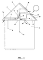
- a conventional house comprising a tiled apex roof 10, a roof space 11 formed under the roof and above the upstairs ceiling 12 of the house, and a main accommodation space 13, which comprises a plurality of rooms including living, reception and bedrooms.
- a ventilating unit 14 is mounted in the roof space 11 and has a plurality of inlet ducts 15, 16, 17 connected to it, with flaps or shutters provided in the ventilating unit 14 for selectively opening and closing the corresponding ends of the inlet ducts 15, 16, 17.
- An outlet duct 18 extends from the ventilating unit 14 through the ceiling 12 to a diffuser 19 mounted to the ceiling, for example in the landing of the house.
- the ventilating unit 14 includes a fan (not shown) driven by an electric motor.
- the first inlet duct 15 extends between the ventilating unit 14 and a point located within the roof or loft space 11.
- the second inlet duct 16 extends between the ventilating unit 14 and an enclosed space 20 which is formed in the roof space 11 under the tiles or roof covering of the most southerly-facing side of the roof.
- This enclosed space 20 may be formed as a partition 22 fitted to extend parallel to the tiled surface of the roof and between adjacent roof trusses: air is able to enter the enclosed space 20, from the exterior, through vents provided in the roof or through the gaps between tiles.
- the third inlet duct 17 extends between the ventilating unit 14 and a point located externally of the house, preferably on the most northerly-facing side of the house and conveniently under the eaves.
- a temperature sensor T 1 , T 2 , T 3 is disposed adjacent the inlet to each inlet duct 15, 16, 17, the temperature sensors being connected by respective cables to a controller of the ventilating unit 14.
- the ventilating unit 14 is also connected via respective cables to a temperature sensor T o and switch S, which are mounted inside the accommodation space 13 of the house.
- the switch S comprises a selector which is operable between winter and summer settings.
- the ventilating unit 14 drives its fan to draw air, normally at a low flow rate, along one of the ducts 15, 16 or 17, depending on which one will provide the warmest air (as determined by the sensors T 1 , T 2 and T 3 ) : the flaps or shutters of the ventilating unit close off the remaining inlet ducts.
- This flow of air is delivered through the outlet duct 18 and into the accommodation space of the house, via the diffuser 19 on the ceiling 12, with the effect of maintaining a slight positive air pressure inside the house: air is forced to flow out of the house through gaps in the doors or windows etc.
- Air is always drawn from the warmest point and thus no significant heat loss should occur.
- the fan flow rate is preferably reduced or the fan switched off if the incoming-air temperatures indicated by sensors T 1 , T 2 and T 3 are below a predetermined minimum level, in order to prevent very cold air from being drawn into the house.
- the ventilating unit 14 When the temperature sensed inside the house, by sensor T o , is substantially below the temperature sensed by any of the sensors T 1 , T 2 or T 3 , the ventilating unit 14 increases the speed of its fan and draws air from the inlet duct 15, 16 or 17 which has the warmest air as its inlet. Typically, the warmest air will be in the enclosed space 20 under the most southerly-facing side of the roof 10. Thus, it will be appreciated that air, which is warmer than the air inside the accommodation space 13 of the house, is drawn from the roof space 11 through either the first, second or third inlet ducts 15, 16 or 17 and supplied by the ventilating unit to raise the temperature inside the accommodation space 13 of the house.
- the ventilating unit 14 draws power from mains supply.
- a solar cell 28 is mounted to the exterior of the most southerly-facing side of the roof 10: the ventilating unit may be arranged to draw its power from the solar cell 28 or from a battery charged by the solar cell 28, instead of from the mains supply, when the output of the solar cell is sufficient.
- the additional power that is required when the fan speeds up is preferably provided by the solar cell 28 or by the battery charged by the solar cell.
- the fan When the selector of switch S is set to its summer setting, the fan normally operates at a slow speed to provide a flow of air into the house, as hereinbefore described.
- the air is preferably drawn from whichever of inlet ducts 15, 16, 17 has the coolest air at its inlet, provided that this air is not too cold (in which case air is drawn from the next coolest inlet or a mixture is drawn from various inlets, or the fan is stopped altogether).
- the ventilating unit 14 increases the speed of its fan and draws air from the duct 15, 16,17 which has the coolest air at its inlet.
- the air inside the roof space 11 is not at such a low temperature as the exterior air, especially the exterior air immediately adjacent the most northerly-facing side of the roof.
- the inlet duct 17 may be used to draw air from this point on hot days.
- air which is cooler than the air inside the main accommodation space 13 of the house, is drawn by the ventilating unit through a selected inlet duct 15, 16, 17 and passed into the accommodation space of the house, in order to provide cooling in the summer.
- the power for the fan is provided by the solar cell 28 or by the rechargeable battery when the output of the solar cell or its battery is sufficient: also, the additional power required, when increased fan speed is demanded, may be provided from the solar cell or the battery charged by it.
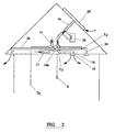
- a solar heater 20' is installed on the south-facing side of the roof, instead of the enclosed space 20 being formed under the roof covering.
- the solar heater 20' comprises a planar enclosure to which the inlet end of the duct 16 is connected, the enclosure having vents or openings for the inlet of replacement air from the exterior. The air within the enclosure is heated by the solar radiation.
- the ventilating unit 14 includes a fan for withdrawing air from the living space of the building, via a duct 24, and expelling the withdrawn air to the exterior via a duct 26.
- the unit 14 includes a heat exchanger 14a, for exchanging heat between the air being expelled and the air being drawn through one of the inlet ducts and delivered into the living space via the air delivery duct 18.
- the heat exchanger 14a serves to enhance the temperature of the incoming air.
- summer mode is selected, then if the air being expelled is cooler than the incoming air, the heat exchanger serves to reduce the temperature of the incoming air.
- a heat store 30 is provided and coupled to one of the inlet ducts (preferably the duct 16 from the solar heating panel 20' on the roof surface or the enclosure 20 under the roof surface).
- the heat store 30 may comprise a tank of water and serves to store heat from the incoming warm air during the day, then transfer this heat back to the incoming cool air at night.
- the heat store 30 is a water tank, then this may be used as a supply of hot water.
- the water tank may be provided with an electric immersion heater for using electricity at low cost overnight to heat the water.
- the switch Whilst the ventilating system which has been described has a switch for selecting winter or summer modes of operation, the switch may be arranged to select an "automatic" mode.
- a temperature sensor T 5 is provided, e.g. in the unit 14 or the outlet duct 18, to sense the temperature of the air being delivered into the living space. Then, if the temperature of the air being delivered is below a threshold value, the controller of the ventilating system determines which source is able to provide the warmest air, and selects the corresponding inlet duct 15, 16 or 17. If instead the temperature of the delivered air is above the threshold value, the controller determines which source is able to provide the coolest air, and selects the corresponding inlet duct 15, 16 or 17.
- the threshold temperature is manually selectable via the switch S.
- the system may simply run at all times in automatic mode, and not have the facility for selecting winter or summer modes.
- the controller is arranged to reduce the speed of or to stop the air delivery fan if the temperature of the available air, sensed at T 1 , T 2 and T 3 , is excessively cold (when warm air is demanded) or excessively warm (when cool air is demanded: further, the fan speed is preferably increased if the interior temperature (sensed at T o ) is substantially lower than the available inlet air (when warm air is demanded) or substantially higher than the available inlet air (when cool air is demanded).
- ventilating systems act to deliver warm air (and not cold air) into the building during winter or cold weather conditions, and act to deliver cool air (and not warm air) into the building during summer or warm weather conditions.
Landscapes
- Engineering & Computer Science (AREA)
- General Engineering & Computer Science (AREA)
- Chemical & Material Sciences (AREA)
- Combustion & Propulsion (AREA)
- Mechanical Engineering (AREA)
- Fluid Mechanics (AREA)
- Physics & Mathematics (AREA)
- Building Environments (AREA)
- Ventilation (AREA)
- Preparation Of Compounds By Using Micro-Organisms (AREA)
- Iron Core Of Rotating Electric Machines (AREA)
- Separation By Low-Temperature Treatments (AREA)
- Input Circuits Of Receivers And Coupling Of Receivers And Audio Equipment (AREA)
- Flow Control (AREA)
- Fluid-Driven Valves (AREA)
Claims (14)
- In einem Gebäude installiertes Lüftungssystem, umfassend eine Lüftungseinheit (14), die ein Gebläse aufweist und so angeordnet ist, um Luft von ausgewählten Einlaßstellen anzusaugen, wobei sich die Einlaßstellen außerhalb des Unterbringungsraums (13) des Gebäudes befinden, und die Luft in den Unterbringungsraum (13) des Gebäudes zuzuführen, eine Mehrzahl von Temperatursensoren (10, 11, 12, 13), und zwar einen für jede Einlaßstelle, aus der die Lüftungseinheit (14) zum Luft Ziehen eingerichtet ist, und einen für den Unterbringungsraum (13) des Gebäudes, und Steuermittel, die auf die Temperatursensoren an den Einlaßstellen ansprechen, um die Einlaßstellen auszuwählen, aus denen die Lüftungseinheit Luft ansaugt.
- Lüftungssystem gemäß Anspruch 1, worin die Steuermittel ausgebildet sind zum Auswählen der Einlaßstelle mit der wärmsten verfügbaren Luft unter kalten Wetterbedingungen und zum Auswählen der Einlaßstelle mit der kühlsten verfügbaren Luft unter warmen Wetterbedingungen.
- Lüftungssystem gemäß Anspruch 2, worin die Steuermittel abhängig sind von der Temperatur der Luft, die dem Unterbringungsraum des Gebäudes zugeführt wird, um zu bestimmen, ob die wärmste verfügbare Luft oder die kühlste verfügbare Luft ausgewählt wird.
- Lüftungssystem gemäß Anspruch 2 oder 3, umfassend Mittel zum Auswählen eines Winter-Betriebsmodus oder eines Sommer-Betriebsmodus.
- Lüftungssystem nach einem beliebigen der vorangehenden Ansprüche, worin die Steuermittel so ausgebildet sind, um die Durchflußmenge des Gebläses in Abhängigkeit von den Temperaturunterschied zwischen dem Unterbringungsraum des Gebäudes und der Temperatur der verfügbaren Einlaßluft oder in Abhängigkeit von der verfügbaren Einlaßlufttemperatur, zu steuern.
- Lüftungssystem nach Anspruch 5, worin die Steuermittel so ausgebildet sind, daß Gebläse anzuhalten oder die Durchflußmenge des Gebläses zu verringern in dem Fall, wenn die Temperatur der verfügbaren Einlaßluft unter einem Mindestwert oder über einem Höchstwert liegt.
- Lüftungssystem gemäß Anspruch 5 oder 6, worin die Steuermittel so ausgebildet sind, um die Durchflußmenge des Gebläses zu erhöhen, bei kalten Wetterbedingungen, in dem Fall, wenn die Temperatur des Unterbringungsraums des Gebäudes niedriger ist als die Temperatur der verfügbaren Einlaßluft um mehr als einen vorbestimmten Wert.
- Lüftungssystem nach einem beliebigen der Ansprüche 5 bis 7, worin die Steuermittel so ausgebildet sind, um die Durchflußmenge des Gebläses zu erhöhen, bei warmen Wetterbedingungen, in dem Fall, wenn die Temperatur des Unterbringungsraums des Gebäudes höher ist als die Temperatur der verfügbaren Einlaßluft um einen vorbestimmten Wert.
- Lüftungssystem nach einem beliebigen der vorangehenden Ansprüche, worin eine der Stellen, von denen die Lüftungseinheit Luft ziehen kann, einen umschlossenen Raum aufweist, der auf oder unter dem bedeckenden Dach angeordnet ist und dazu ausgebildet ist, daß das umschlossene Luftvolumen durch Sonnenstrahlung erwärmt wird.
- Lüftungssystem nach einem beliebigen der vorangehenden Ansprüche, worin eine der Stellen, von denen die Lüftungseinheit Luft zieht, eine Stelle außerhalb des Gebäudes ist, an der keine oder nur geringe Sonnenstrahlung aufgenommen wird.
- Lüftungssystem nach einem beliebigen der vorangehenden Ansprüche, ferner umfassend ein zweites Gebläse zum Absaugen von Luft aus dem Unterbringungsraum des Gebäudes und zum Abführen der Luft an die äußere Umgebung des Gebäudes.
- Lüftungssystem gemäß Anspruch 11, weiter umfassend einen Wärmetauscher zum Übertragen von Wärme zwischen der dem Unterbringungsraum des Gebäudes abgeführten und der dorthin zugeführten Luft.
- Lüftungssystem gemäß Anspruch 12, worin die Steuermittel dazu ausgebildet sind, die Durchflußmenge des zweiten Gebläses zu verringern oder zu stoppen, oder den Wärmetauscher zu umgehen, in dem Fall, wenn die Temperatur der abzuführenden Luft, bei kalten Wetterbedingungen, niedriger ist als die der hereinkommenden Luft, oder, bei warmen Wetterbedingungen, größer als die der hereinkommenden Luft ist.
- Lüftungssystem nach einem beliebigen der vorangehenden Ansprüche, weiter umfassend Wärmespeichermittel, die mit einer Leitung für hereinkommende Luft verbunden sind und so ausgebildet sind, um Wärme aus der hereinkommenden warmen Luft während des Tages zu speichern und die Wärme an die hereinkommende Luft während der Nacht abzugeben.
Applications Claiming Priority (3)
| Application Number | Priority Date | Filing Date | Title |
|---|---|---|---|
| GB9818305 | 1998-08-22 | ||
| GBGB9818305.6A GB9818305D0 (en) | 1998-08-22 | 1998-08-22 | Ventilating system |
| PCT/GB1999/002766 WO2000011410A1 (en) | 1998-08-22 | 1999-08-23 | Ventilating system |
Publications (2)
| Publication Number | Publication Date |
|---|---|
| EP1105687A1 EP1105687A1 (de) | 2001-06-13 |
| EP1105687B1 true EP1105687B1 (de) | 2003-11-05 |
Family
ID=10837658
Family Applications (1)
| Application Number | Title | Priority Date | Filing Date |
|---|---|---|---|
| EP99940387A Expired - Lifetime EP1105687B1 (de) | 1998-08-22 | 1999-08-23 | Lüftungssystem |
Country Status (7)
| Country | Link |
|---|---|
| EP (1) | EP1105687B1 (de) |
| AT (1) | ATE253713T1 (de) |
| AU (1) | AU744141B2 (de) |
| DE (1) | DE69912616D1 (de) |
| GB (1) | GB9818305D0 (de) |
| NZ (1) | NZ509926A (de) |
| WO (1) | WO2000011410A1 (de) |
Families Citing this family (5)
| Publication number | Priority date | Publication date | Assignee | Title |
|---|---|---|---|---|
| EP1225399A1 (de) * | 2001-01-18 | 2002-07-24 | Holding Aktiengesellschaft Belimo | Anordnung zum Überwachen und Steuern der natürlichen Belüftung von Raumeinheiten und eine Verwendung der Anordnung |
| GB0117220D0 (en) | 2001-07-14 | 2001-09-05 | Nuaire Ltd | Ventilating system |
| DE102005035496A1 (de) * | 2005-07-26 | 2007-02-01 | Wolfgang Dr.-Ing. Horn | Verfahren zum Schutz vor gefährlichen Gasen mit Wärmerückgewinnungsgeräten |
| CN100420902C (zh) * | 2006-07-19 | 2008-09-24 | 北京工业大学 | 应用太阳能相变蓄热的全热回收新风节能系统 |
| EP3696469B1 (de) | 2019-02-13 | 2021-06-02 | Airmaster A/S | Hybrides lüftungssystem |
Family Cites Families (6)
| Publication number | Priority date | Publication date | Assignee | Title |
|---|---|---|---|---|
| US4312226A (en) * | 1979-11-30 | 1982-01-26 | Mark Controls Corporation | Comparator |
| US4986469B1 (en) * | 1990-06-26 | 1999-08-17 | James A Sutton Jr | Method of ventilating an animal enclosure in response to temperature |
| EP0783655B1 (de) * | 1994-08-08 | 1999-06-23 | Van Holsteijn & Kemna Special Products B.V. | Zimmerklimaanlage für ein heizungs-, kühlungs- und lüftungssystem |
| NL9401632A (nl) * | 1994-10-04 | 1996-05-01 | Fancom Bv | Debietsensor. |
| DE19654542C2 (de) * | 1996-12-27 | 2000-08-17 | Albert Bauer | Klimatisierungsvorrichtung |
| US5718627A (en) * | 1997-02-03 | 1998-02-17 | Wicks; Edward A. | System and method for smoke free elevator shaft |
-
1998
- 1998-08-22 GB GBGB9818305.6A patent/GB9818305D0/en not_active Ceased
-
1999
- 1999-08-23 DE DE69912616T patent/DE69912616D1/de not_active Expired - Lifetime
- 1999-08-23 WO PCT/GB1999/002766 patent/WO2000011410A1/en not_active Ceased
- 1999-08-23 AT AT99940387T patent/ATE253713T1/de not_active IP Right Cessation
- 1999-08-23 NZ NZ509926A patent/NZ509926A/en unknown
- 1999-08-23 EP EP99940387A patent/EP1105687B1/de not_active Expired - Lifetime
- 1999-08-23 AU AU54373/99A patent/AU744141B2/en not_active Ceased
Also Published As
| Publication number | Publication date |
|---|---|
| DE69912616D1 (de) | 2003-12-11 |
| ATE253713T1 (de) | 2003-11-15 |
| AU5437399A (en) | 2000-03-14 |
| WO2000011410A1 (en) | 2000-03-02 |
| AU744141B2 (en) | 2002-02-14 |
| EP1105687A1 (de) | 2001-06-13 |
| GB9818305D0 (en) | 1998-10-14 |
| NZ509926A (en) | 2002-04-26 |
Similar Documents
| Publication | Publication Date | Title |
|---|---|---|
| US20020117166A1 (en) | Solar-system house | |
| JP4485539B2 (ja) | ソーラーシステムハウス | |
| US4552205A (en) | Dual storage heating and cooling system | |
| KR101441098B1 (ko) | 열 펌프 시스템 | |
| EP1105687B1 (de) | Lüftungssystem | |
| JPH0670528B2 (ja) | ソーラーシステムハウス | |
| EP0232068A2 (de) | Sonnenheizung | |
| JP5926711B2 (ja) | 暖房システム | |
| JP4751363B2 (ja) | 床暖房システム | |
| JPH0579707A (ja) | ソーラーシステムハウスおよびそれに使用するハンドリングボツクス | |
| GB2062213A (en) | Solar heating | |
| US20160033145A1 (en) | Room-to-Room Heat Pump | |
| JP2597242B2 (ja) | ソーラーシステムハウス | |
| JPH0735419A (ja) | 太陽熱利用建築物 | |
| EP1407198B1 (de) | Lüftungsanlage | |
| JP2017219293A (ja) | 換気システム | |
| JP2004076985A (ja) | 建物の空調システム | |
| JPH05296514A (ja) | 地下室付き住宅の通風機構 | |
| JPH01256740A (ja) | 住宅の温度制御方法 | |
| NO347490B1 (en) | A ventilation system and a method for preheating a supply air in the same | |
| JP3909405B2 (ja) | 暖房システム | |
| JPH08233375A (ja) | ソーラーシステムハウス | |
| JPH11101474A (ja) | 家屋への空気取入れ方法及び装置 | |
| Erhorn | System 5: Closed collection loop with open discharge loop | |
| JPH06313631A (ja) | ソーラーシステムハウス |
Legal Events
| Date | Code | Title | Description |
|---|---|---|---|
| PUAI | Public reference made under article 153(3) epc to a published international application that has entered the european phase |
Free format text: ORIGINAL CODE: 0009012 |
|
| 17P | Request for examination filed |
Effective date: 20010219 |
|
| AK | Designated contracting states |
Kind code of ref document: A1 Designated state(s): AT BE CH CY DE DK ES FI FR GB GR IE IT LI LU MC NL PT SE |
|
| AX | Request for extension of the european patent |
Free format text: AL;LT;LV;MK;RO;SI |
|
| GRAH | Despatch of communication of intention to grant a patent |
Free format text: ORIGINAL CODE: EPIDOS IGRA |
|
| GRAS | Grant fee paid |
Free format text: ORIGINAL CODE: EPIDOSNIGR3 |
|
| GRAA | (expected) grant |
Free format text: ORIGINAL CODE: 0009210 |
|
| AK | Designated contracting states |
Kind code of ref document: B1 Designated state(s): AT BE CH CY DE DK ES FI FR GB GR IE IT LI LU MC NL PT SE |
|
| PG25 | Lapsed in a contracting state [announced via postgrant information from national office to epo] |
Ref country code: NL Free format text: LAPSE BECAUSE OF FAILURE TO SUBMIT A TRANSLATION OF THE DESCRIPTION OR TO PAY THE FEE WITHIN THE PRESCRIBED TIME-LIMIT Effective date: 20031105 Ref country code: LI Free format text: LAPSE BECAUSE OF FAILURE TO SUBMIT A TRANSLATION OF THE DESCRIPTION OR TO PAY THE FEE WITHIN THE PRESCRIBED TIME-LIMIT Effective date: 20031105 Ref country code: IT Free format text: LAPSE BECAUSE OF FAILURE TO SUBMIT A TRANSLATION OF THE DESCRIPTION OR TO PAY THE FEE WITHIN THE PRESCRIBED TIME-LIMIT;WARNING: LAPSES OF ITALIAN PATENTS WITH EFFECTIVE DATE BEFORE 2007 MAY HAVE OCCURRED AT ANY TIME BEFORE 2007. THE CORRECT EFFECTIVE DATE MAY BE DIFFERENT FROM THE ONE RECORDED. Effective date: 20031105 Ref country code: FI Free format text: LAPSE BECAUSE OF FAILURE TO SUBMIT A TRANSLATION OF THE DESCRIPTION OR TO PAY THE FEE WITHIN THE PRESCRIBED TIME-LIMIT Effective date: 20031105 Ref country code: CY Free format text: LAPSE BECAUSE OF FAILURE TO SUBMIT A TRANSLATION OF THE DESCRIPTION OR TO PAY THE FEE WITHIN THE PRESCRIBED TIME-LIMIT Effective date: 20031105 Ref country code: CH Free format text: LAPSE BECAUSE OF FAILURE TO SUBMIT A TRANSLATION OF THE DESCRIPTION OR TO PAY THE FEE WITHIN THE PRESCRIBED TIME-LIMIT Effective date: 20031105 Ref country code: BE Free format text: LAPSE BECAUSE OF FAILURE TO SUBMIT A TRANSLATION OF THE DESCRIPTION OR TO PAY THE FEE WITHIN THE PRESCRIBED TIME-LIMIT Effective date: 20031105 Ref country code: AT Free format text: LAPSE BECAUSE OF FAILURE TO SUBMIT A TRANSLATION OF THE DESCRIPTION OR TO PAY THE FEE WITHIN THE PRESCRIBED TIME-LIMIT Effective date: 20031105 |
|
| REG | Reference to a national code |
Ref country code: GB Ref legal event code: FG4D |
|
| REG | Reference to a national code |
Ref country code: CH Ref legal event code: EP |
|
| REF | Corresponds to: |
Ref document number: 69912616 Country of ref document: DE Date of ref document: 20031211 Kind code of ref document: P |
|
| REG | Reference to a national code |
Ref country code: IE Ref legal event code: FG4D |
|
| PG25 | Lapsed in a contracting state [announced via postgrant information from national office to epo] |
Ref country code: SE Free format text: LAPSE BECAUSE OF FAILURE TO SUBMIT A TRANSLATION OF THE DESCRIPTION OR TO PAY THE FEE WITHIN THE PRESCRIBED TIME-LIMIT Effective date: 20040205 Ref country code: GR Free format text: LAPSE BECAUSE OF FAILURE TO SUBMIT A TRANSLATION OF THE DESCRIPTION OR TO PAY THE FEE WITHIN THE PRESCRIBED TIME-LIMIT Effective date: 20040205 Ref country code: DK Free format text: LAPSE BECAUSE OF FAILURE TO SUBMIT A TRANSLATION OF THE DESCRIPTION OR TO PAY THE FEE WITHIN THE PRESCRIBED TIME-LIMIT Effective date: 20040205 |
|
| PG25 | Lapsed in a contracting state [announced via postgrant information from national office to epo] |
Ref country code: DE Free format text: LAPSE BECAUSE OF FAILURE TO SUBMIT A TRANSLATION OF THE DESCRIPTION OR TO PAY THE FEE WITHIN THE PRESCRIBED TIME-LIMIT Effective date: 20040206 |
|
| PG25 | Lapsed in a contracting state [announced via postgrant information from national office to epo] |
Ref country code: ES Free format text: LAPSE BECAUSE OF FAILURE TO SUBMIT A TRANSLATION OF THE DESCRIPTION OR TO PAY THE FEE WITHIN THE PRESCRIBED TIME-LIMIT Effective date: 20040216 |
|
| NLV1 | Nl: lapsed or annulled due to failure to fulfill the requirements of art. 29p and 29m of the patents act | ||
| LTIE | Lt: invalidation of european patent or patent extension |
Effective date: 20031105 |
|
| REG | Reference to a national code |
Ref country code: CH Ref legal event code: PL |
|
| ET | Fr: translation filed | ||
| PG25 | Lapsed in a contracting state [announced via postgrant information from national office to epo] |
Ref country code: LU Free format text: LAPSE BECAUSE OF NON-PAYMENT OF DUE FEES Effective date: 20040823 |
|
| PG25 | Lapsed in a contracting state [announced via postgrant information from national office to epo] |
Ref country code: MC Free format text: LAPSE BECAUSE OF NON-PAYMENT OF DUE FEES Effective date: 20040831 |
|
| PLBE | No opposition filed within time limit |
Free format text: ORIGINAL CODE: 0009261 |
|
| STAA | Information on the status of an ep patent application or granted ep patent |
Free format text: STATUS: NO OPPOSITION FILED WITHIN TIME LIMIT |
|
| 26N | No opposition filed |
Effective date: 20040806 |
|
| PG25 | Lapsed in a contracting state [announced via postgrant information from national office to epo] |
Ref country code: PT Free format text: LAPSE BECAUSE OF NON-PAYMENT OF DUE FEES Effective date: 20040405 |
|
| REG | Reference to a national code |
Ref country code: FR Ref legal event code: PLFP Year of fee payment: 18 |
|
| REG | Reference to a national code |
Ref country code: FR Ref legal event code: PLFP Year of fee payment: 19 |
|
| REG | Reference to a national code |
Ref country code: FR Ref legal event code: PLFP Year of fee payment: 20 |
|
| PGFP | Annual fee paid to national office [announced via postgrant information from national office to epo] |
Ref country code: FR Payment date: 20180827 Year of fee payment: 20 Ref country code: IE Payment date: 20180828 Year of fee payment: 20 |
|
| PGFP | Annual fee paid to national office [announced via postgrant information from national office to epo] |
Ref country code: GB Payment date: 20180713 Year of fee payment: 20 |
|
| REG | Reference to a national code |
Ref country code: GB Ref legal event code: PE20 Expiry date: 20190822 |
|
| REG | Reference to a national code |
Ref country code: IE Ref legal event code: MK9A |
|
| PG25 | Lapsed in a contracting state [announced via postgrant information from national office to epo] |
Ref country code: IE Free format text: LAPSE BECAUSE OF EXPIRATION OF PROTECTION Effective date: 20190823 |
|
| PG25 | Lapsed in a contracting state [announced via postgrant information from national office to epo] |
Ref country code: GB Free format text: LAPSE BECAUSE OF EXPIRATION OF PROTECTION Effective date: 20190822 |