EP1105885B1 - Conducteurs supraconducteurs - Google Patents
Conducteurs supraconducteurs Download PDFInfo
- Publication number
- EP1105885B1 EP1105885B1 EP99956481A EP99956481A EP1105885B1 EP 1105885 B1 EP1105885 B1 EP 1105885B1 EP 99956481 A EP99956481 A EP 99956481A EP 99956481 A EP99956481 A EP 99956481A EP 1105885 B1 EP1105885 B1 EP 1105885B1
- Authority
- EP
- European Patent Office
- Prior art keywords
- superconducting
- superconductor
- conductor
- electrical conductor
- thermal
- Prior art date
- Legal status (The legal status is an assumption and is not a legal conclusion. Google has not performed a legal analysis and makes no representation as to the accuracy of the status listed.)
- Expired - Lifetime
Links
- 239000004020 conductor Substances 0.000 title claims description 39
- 239000002887 superconductor Substances 0.000 claims description 88
- 239000000463 material Substances 0.000 claims description 66
- 239000002131 composite material Substances 0.000 claims description 28
- 239000002470 thermal conductor Substances 0.000 claims description 24
- 239000011159 matrix material Substances 0.000 claims description 13
- 239000010935 stainless steel Substances 0.000 claims description 10
- 229910001220 stainless steel Inorganic materials 0.000 claims description 10
- 229910052751 metal Inorganic materials 0.000 claims description 7
- 239000002184 metal Substances 0.000 claims description 7
- 239000004642 Polyimide Substances 0.000 claims description 4
- 229920001721 polyimide Polymers 0.000 claims description 4
- 239000003381 stabilizer Substances 0.000 description 23
- 230000004888 barrier function Effects 0.000 description 12
- 230000007704 transition Effects 0.000 description 12
- 239000003017 thermal stabilizer Substances 0.000 description 11
- 239000000758 substrate Substances 0.000 description 7
- 238000001816 cooling Methods 0.000 description 5
- 239000010949 copper Substances 0.000 description 5
- 230000006378 damage Effects 0.000 description 5
- RYGMFSIKBFXOCR-UHFFFAOYSA-N Copper Chemical compound [Cu] RYGMFSIKBFXOCR-UHFFFAOYSA-N 0.000 description 4
- 239000000919 ceramic Substances 0.000 description 4
- 230000035882 stress Effects 0.000 description 4
- 229910000831 Steel Inorganic materials 0.000 description 3
- 239000011248 coating agent Substances 0.000 description 3
- 238000000576 coating method Methods 0.000 description 3
- 229910052802 copper Inorganic materials 0.000 description 3
- 238000005520 cutting process Methods 0.000 description 3
- 230000007423 decrease Effects 0.000 description 3
- 238000000034 method Methods 0.000 description 3
- 230000008569 process Effects 0.000 description 3
- 238000011084 recovery Methods 0.000 description 3
- 239000010959 steel Substances 0.000 description 3
- 229910001316 Ag alloy Inorganic materials 0.000 description 2
- 239000005751 Copper oxide Substances 0.000 description 2
- 239000004593 Epoxy Substances 0.000 description 2
- PXHVJJICTQNCMI-UHFFFAOYSA-N Nickel Chemical compound [Ni] PXHVJJICTQNCMI-UHFFFAOYSA-N 0.000 description 2
- BQCADISMDOOEFD-UHFFFAOYSA-N Silver Chemical compound [Ag] BQCADISMDOOEFD-UHFFFAOYSA-N 0.000 description 2
- 229910000431 copper oxide Inorganic materials 0.000 description 2
- 229960004643 cupric oxide Drugs 0.000 description 2
- 238000009826 distribution Methods 0.000 description 2
- 239000012212 insulator Substances 0.000 description 2
- 229920003223 poly(pyromellitimide-1,4-diphenyl ether) Polymers 0.000 description 2
- 229910052709 silver Inorganic materials 0.000 description 2
- 239000004332 silver Substances 0.000 description 2
- 229910000838 Al alloy Inorganic materials 0.000 description 1
- 229910000881 Cu alloy Inorganic materials 0.000 description 1
- 229910002480 Cu-O Inorganic materials 0.000 description 1
- XEEYBQQBJWHFJM-UHFFFAOYSA-N Iron Chemical group [Fe] XEEYBQQBJWHFJM-UHFFFAOYSA-N 0.000 description 1
- 229910000990 Ni alloy Inorganic materials 0.000 description 1
- OSOKRZIXBNTTJX-UHFFFAOYSA-N [O].[Ca].[Cu].[Sr].[Bi] Chemical compound [O].[Ca].[Cu].[Sr].[Bi] OSOKRZIXBNTTJX-UHFFFAOYSA-N 0.000 description 1
- 239000000853 adhesive Substances 0.000 description 1
- 230000001070 adhesive effect Effects 0.000 description 1
- PNEYBMLMFCGWSK-UHFFFAOYSA-N aluminium oxide Inorganic materials [O-2].[O-2].[O-2].[Al+3].[Al+3] PNEYBMLMFCGWSK-UHFFFAOYSA-N 0.000 description 1
- HVBPAXNJXIULHK-UHFFFAOYSA-N barium;calcium;copper;oxomercury Chemical compound [Ca].[Cu].[Ba].[Hg]=O HVBPAXNJXIULHK-UHFFFAOYSA-N 0.000 description 1
- 239000011575 calcium Substances 0.000 description 1
- 230000008859 change Effects 0.000 description 1
- 239000000805 composite resin Substances 0.000 description 1
- 150000001875 compounds Chemical class 0.000 description 1
- 238000009792 diffusion process Methods 0.000 description 1
- 230000008034 disappearance Effects 0.000 description 1
- 238000010292 electrical insulation Methods 0.000 description 1
- 230000005611 electricity Effects 0.000 description 1
- 239000003822 epoxy resin Substances 0.000 description 1
- 239000011888 foil Substances 0.000 description 1
- 239000011521 glass Substances 0.000 description 1
- 239000003365 glass fiber Substances 0.000 description 1
- LNEPOXFFQSENCJ-UHFFFAOYSA-N haloperidol Chemical compound C1CC(O)(C=2C=CC(Cl)=CC=2)CCN1CCCC(=O)C1=CC=C(F)C=C1 LNEPOXFFQSENCJ-UHFFFAOYSA-N 0.000 description 1
- 230000000977 initiatory effect Effects 0.000 description 1
- 229910052500 inorganic mineral Inorganic materials 0.000 description 1
- 238000009413 insulation Methods 0.000 description 1
- 239000004922 lacquer Substances 0.000 description 1
- 238000003475 lamination Methods 0.000 description 1
- 229910052745 lead Inorganic materials 0.000 description 1
- 239000007788 liquid Substances 0.000 description 1
- 230000007246 mechanism Effects 0.000 description 1
- 229910001092 metal group alloy Inorganic materials 0.000 description 1
- 229910044991 metal oxide Inorganic materials 0.000 description 1
- 239000011707 mineral Substances 0.000 description 1
- 239000000203 mixture Substances 0.000 description 1
- 230000007935 neutral effect Effects 0.000 description 1
- 239000000615 nonconductor Substances 0.000 description 1
- 238000013021 overheating Methods 0.000 description 1
- 229920000647 polyepoxide Polymers 0.000 description 1
- 238000004080 punching Methods 0.000 description 1
- 239000011347 resin Substances 0.000 description 1
- 229920005989 resin Polymers 0.000 description 1
- 238000000926 separation method Methods 0.000 description 1
- 230000008646 thermal stress Effects 0.000 description 1
- 229920001169 thermoplastic Polymers 0.000 description 1
- 239000004416 thermosoftening plastic Substances 0.000 description 1
- 230000001052 transient effect Effects 0.000 description 1
- 229910021521 yttrium barium copper oxide Inorganic materials 0.000 description 1
Images




Classifications
-
- H—ELECTRICITY
- H01—ELECTRIC ELEMENTS
- H01B—CABLES; CONDUCTORS; INSULATORS; SELECTION OF MATERIALS FOR THEIR CONDUCTIVE, INSULATING OR DIELECTRIC PROPERTIES
- H01B12/00—Superconductive or hyperconductive conductors, cables, or transmission lines
- H01B12/16—Superconductive or hyperconductive conductors, cables, or transmission lines characterised by cooling
-
- H—ELECTRICITY
- H10—SEMICONDUCTOR DEVICES; ELECTRIC SOLID-STATE DEVICES NOT OTHERWISE PROVIDED FOR
- H10N—ELECTRIC SOLID-STATE DEVICES NOT OTHERWISE PROVIDED FOR
- H10N60/00—Superconducting devices
- H10N60/30—Devices switchable between superconducting and normal states
-
- Y—GENERAL TAGGING OF NEW TECHNOLOGICAL DEVELOPMENTS; GENERAL TAGGING OF CROSS-SECTIONAL TECHNOLOGIES SPANNING OVER SEVERAL SECTIONS OF THE IPC; TECHNICAL SUBJECTS COVERED BY FORMER USPC CROSS-REFERENCE ART COLLECTIONS [XRACs] AND DIGESTS
- Y02—TECHNOLOGIES OR APPLICATIONS FOR MITIGATION OR ADAPTATION AGAINST CLIMATE CHANGE
- Y02E—REDUCTION OF GREENHOUSE GAS [GHG] EMISSIONS, RELATED TO ENERGY GENERATION, TRANSMISSION OR DISTRIBUTION
- Y02E40/00—Technologies for an efficient electrical power generation, transmission or distribution
- Y02E40/60—Superconducting electric elements or equipment; Power systems integrating superconducting elements or equipment
Definitions
- the invention relates to superconducting conductors such as composite superconductors.
- Superconductors are generally classified as either low or high temperature superconductors.
- An important property of the superconductor is the disappearance of its electrical resistance when it is cooled below its critical temperature T c .
- T c critical temperature
- H c critical magnetic field
- LTS low temperature superconducting
- HTS high temperature superconducting
- the transition characteristic of an HTS material is generally not abrupt. Rather, upon reaching its critical temperature or critical current value, the superconductivity of the HTS material gradually diminishes as its temperature or current flow rises until it reaches a temperature or current value at which the material no longer has any superconductivity characteristic.
- the patent US 4,977,039 is concerned with a plurality of Low-Tc superconductor wires assembled to form a cable.
- a thermal conductor film for longitudinal heat conduction is applied to the wire.
- Said preferably metallic thermal conductor film is separated from the composite conductor by virtue of an insulator film with a thickness in the range of 1 ⁇ m to 100 ⁇ m.
- the patent US 3,959,549 discloses a flexible multi-layered electrical insulation for deep-cooled cables of Low-Tc superconductors.
- the insulation is a laminate comprising layers of spun bonded papers and layers of insulating foil, and is arranged between two concentric tubular conductors of the cable.
- the patent US 5,102,865 proposes a metallic substrate for a ceramic (High-Tc) superconductor, with an oxide interface layer as a diffusion barrier.
- the superconductor may eventually be applied to both sides of a ribbon-type substrate (Figs.3 and 4).
- the invention features an electrical conductor well-suited for superconducting current-limiting applications, as disclosed in claim 1.
- the superconductor member is a composite having superconducting material and a non-superconducting, electrically conductive matrix material.
- the superconductor member is a bulk superconducting material.
- the superconductor member is a composite having superconducting material mechanically supported by an substantially non-conductive matrix material.
- the electrical conductor is configured to control the manner in which the superconductor member transitions from its superconducting state to its non-superconducting (i.e., normal) state due to, for example, a fault current condition.
- the electrical conductor includes a thermal conductor attached to and along the length of the superconductor member, and an electrically-insulative material disposed between the thermal conductor and length of superconductor member, the electrically-insulative material having a thickness for allowing heat from the superconductor member to be conveyed to the thermal conductor.
- a superconducting current-limiting device in another aspect of the invention, includes a support structure (e.g., an inner support tube) and the above-described electrical conductor disposed on the support structure.
- a support structure e.g., an inner support tube
- the above-described electrical conductor disposed on the support structure.
- the superconductor member serves to carry the current during non-fault conditions with low electrical loss.
- a superconducting composite having the superconducting material and metal matrix, the matrix can provide an alternate current path to compensate for localized inhomogeneities in the superconductor during non-fault conditions.
- the member carries the fault current with a high resistance for short periods of time.
- the thermal conductor serves as a thermal stabilizer and a heat sink during transient fault current events. In general, the thermal conductor prevents the superconducting material from getting too hot during a fault condition.
- the electrical conductor must not get too hot for two reasons: 1) it must have a quick thermal recovery characteristic, and 2) rapid large changes in temperature can cause thermal stresses sufficient to destroy the superconducting material.
- the thermal conductor is directly or indirectly thermally connected to a cooling channel.
- the cooling channel can be a liquid cryogen bath, gas cooling, or a conduction-cooling path (i.e., copper or alumina).
- the electrically insulative material acts as a small thermal and electrical barrier having a two fold purpose. First, the insulative material prevents current transfer from the superconductor member into the thermal conductor. Second, the insulative material causes a delay in the heat transfer between superconductor member and the thermal barrier so that the superconducting material can completely revert to its normal, non-superconducting state.
- the electrically-insulative material provides a thermal barrier that reduces the time needed for the superconductor to transition from a superconducting state to a non-superconducting state, thereby reducing the amount of current flowing through the superconducting material of the member and lowering the total current flowing through the electrical conductor. As a result, possible damage to the superconductor member caused by the excessive current flow and mechanical stresses (e.g., hoop stresses) is minimized.
- Embodiments of either of the aspects of the invention may include one or more of the following features.
- the superconducting material is in the form of a plurality of superconducting filaments, the superconducting filaments surrounded by a non-superconducting, metal matrix (e.g., silver or silver alloy).
- a non-superconducting, metal matrix e.g., silver or silver alloy.
- the superconducting material is in monolithic form as a coating on a non-conductive, or preferably a conductive, ceramic buffer layer supported on a metal substrate (e.g., a nickel, copper or aluminum alloy).
- the thermal conductor is formed of spaced-apart thermally-conductive elements.
- a second laminate is disposed on the first laminate and includes a second sheet of electrically-insulative material disposed on the first plurality of the thermal conductive elements of the first laminate and a second thermal conductor (preferably formed of a second plurality of spaced-apart thermally-conductive elements) attached to the second electrically-insulative material.
- the thermally-conductive elements of the first laminate and the thermally-conductive elements of the second laminate are offset from each other relative to the length of the superconductor member.
- the electrical conductor has increased mechanical strength, particularly in wound structures.
- the first laminate is attached to a first side of the length of the superconductor member and the second laminate is attached to a second, opposite side of the length of the superconductor member.
- the superconductor member in this form is "sandwiched" between two stabilizer members, thereby providing improved thermal stability and mechanical strength.
- the superconductor member is in the form of a tape having a thickness in a range between about 25 to 300 microns.
- the superconducting material is formed of a high temperature, anisotropic superconducting material.
- the thermal conductor may be formed from a metal, a metal alloy or an electrical insulator with good thermal conductivity such as a highly mineral filled resin, but preferably is formed of stainless steel.
- Each of the thermally conductive elements have a thickness in a range between about 100 and 1,000 microns.
- the electrically-insulative material is formed of a glass epoxy or other material, such as lacquer cured by conventional or UV systems, thermoplastics, epoxy resins, or composites (i.e. glass fiber/resin composites or impregnated papers), capable of serving as an insulator at cryogenic temperatures.
- the electrically-insulative material is a polyimide material having a thickness in a range between about 5 and 50 microns.
- the superconducting material is in monolithic form with the non-superconducting matrix in intimate contact with the superconducting material.
- a superconducting composite 10 includes a superconductor tape 12 formed of high temperature superconductor (HTS) material, such as those made from superconducting ceramics, including metallic oxides, which are typically anisotropic, meaning that they generally conduct better, relative to the crystalline structure, in one direction than another.
- HTS high temperature superconductor
- Anisotropic high temperature superconductors include, but are not limited to, the family of Cu-O-based ceramic superconductors, such as members of the rare-earth-copper-oxide family (YBCO), the thallium-barium-calcium-copper-oxide family (TBCCO), the mercury-barium-calcium-copper-oxide family (HgBCCO), and the bismuth strontium calcium copper oxide family (BSCCO). These compounds may be doped with stoichiometric amounts of lead or other materials to improve properties (e.g., (Bi,Pb) 2 Sr 2 Ca 2 Cu 3 O 10- ⁇ ).
- YBCO rare-earth-copper-oxide family
- THCCO thallium-barium-calcium-copper-oxide family
- HgBCCO mercury-barium-calcium-copper-oxide family
- BSCCO bismuth strontium calcium copper oxide family
- Superconductor tape 12 has a relatively high aspect ratio (i.e., it width is greater than its thickness) and is fabricated as a multi-filament composite superconductor including individual high temperature superconducting filaments which extend substantially the length of the multi-filament composite conductor and are surrounded by a matrix-forming material (e.g., silver or silver alloy). It may typically have a thickness greater than about 5 microns and up to about 500 microns, preferably 10 to 100 microns.
- a matrix-forming material e.g., silver or silver alloy
- any incremental current above I c is shared between the superconductor and matrix material based on the onset of resistance in the superconductor.
- the ratio of superconducting material to the total amount of material (i.e., the matrix-forming material and superconducting material) in a given cross-sectional area is known as the "fill factor" and is generally less than 50%.
- the matrix forming material conducts electricity, it is not superconducting. Together, the superconducting filaments and the matrix-forming material form a composite multifilament high temperature superconducting member.
- Laminated over superconductor tape 12 is a stabilizer 13 which provides a thermal path for heat generated within the superconductor tape 12 during the period when the tape is transitioning from its superconducting to its normal state for example, due to a fault current.
- stabilizer 13 provides mechanical support to superconductor tape 12 by absorbing mechanical stresses (e.g., Lorentz forces, hoop stress) caused by thermal expansion in the tape during the transition period.
- mechanical stresses e.g., Lorentz forces, hoop stress
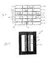
- Stabilizer 13 is formed as layers of discontinuous stabilizer members 14a, 14b, 14c, each having a thermally conductive strip 16a, 16b, 16c disposed over an electrically insulative layer 18a, 18b, 18c.
- additional stabilizer members 14d, 14e, 14f having corresponding conductive strips 16d, 16e, 16f which overlie insulative layers 18d, 18e, 18f may be provided on the opposite side of superconductor tape 14, so that superconductor tape 12 lies along a neutral plane of composite 10.
- Conductive strips 16a-16f are formed of a material of high thermal conductivity and characterized by high modulus, high strength, and flexibility. In certain embodiments, conductive strips 16a-16f are formed of metal, such as stainless steel or copper having good thermal conductivity characteristics at least at the low temperatures in which the invention is operated.
- insulative layers 18a-18f are formed of an adhesive-backed polyimide material (e.g., Kapton ® , a product of E.I. Dupont de Nemours, Wilmington, DE) having a thickness (e.g., 5 to 25 microns) much less, typically 5 to 100 times less and preferably at least an order of magnitude less, than that of conductive strips 16a, 16b, 16c (e.g., 300 microns).
- insulative layers 18a-18f present a thermal barrier between superconducting composite 10 and stabilizer members 14a, 14b, 14c and preferably has a thermal conductivity at least about an order of magnitude lower than that of stainless steel.
- each of insulative layers 18a-18f is selected to control the speed of the transition of the superconducting material superconductor tape 12 from its superconducting condition to its normal, non superconducting condition.
- the superconducting filaments transition to their non-superconducting state so that current flows in the matrix material of the composite, rather than the filaments which have a relatively higher conductivity characteristic in its non-superconducting state.
- the total amount of power dissipated in superconducting composite 10 is advantageously reduced and possible destruction of the superconducting filaments is minimized.
- each strip 16a-16f includes discontinuities 20 in the form of gaps along their length to increase the resistivity of stabilizer members 14a-14f at the location of the imperfection.
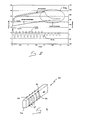
- FIG. 3 the fault current limiting characteristics of a superconductor wire without a thermal stabilizer is shown.
- waveforms for the current flowing through and temperature of an HTS superconductor (along ordinate) as a function of time (abscissa) are shown.
- Current waveform 100 is shown initially in a fault condition (e.g., lightning strike) with the current at point 102 exceeding 400 amperes.
- Temperature waveform 110 of the HTS superconductor is shown to immediately increase at the outset of the fault. Shortly after initiation of the fault (point 104), current waveform 100 drops to a steady state condition with temperature waveform 110 continuing to steadily increase over a 200 millisecond time period, until the fault condition is removed (point 106). At this point, however, the temperature of the superconductor exceeds 400EK, an increase of over 300EK.
- an HTS superconductor subjected to increases of over 100EK experience significant damage.
- a discontinuous stainless steel member serving as a thermal stabilizer which is disposed along and in direct contact with the same HTS superconductor wire of Fig. 3, is shown.
- a current waveform 200 once again is shown initially in a fault condition (point 202).
- temperature waveform 210 of the HTS superconductor steadily increases at the onset of the fault.
- the temperature waveform 212 of the stabilizer substantially follows the temperature waveform of the superconductor.
- the thermal stabilizer tends to decrease the magnitude of the fault current waveform, because the thermal stabilizer and superconductor are in intimate contact, there is no mechanism to force the high temperature superconductor into a normal, non-superconducting state.
- a discontinuous stainless steel member disposed over the HTS superconductor and a thermal barrier (e.g., Kapton ® layer) disposed therebetween is shown.
- current waveform 300 is shown initially at a fault condition (point 302).
- the HTS superconductor member is separated from the discontinuous stainless steel member by the thermal barrier, their respective temperatures do not track each other. Indeed, unlike the arrangement discussed above in conjunction with Fig. 4, because the superconductor member and stabilizer are separated, the temperature of the superconductor increases rapidly from approximately 60EK to about 90EK (point 304).
- the superconductor filaments in the superconductor wire reach their critical current values very quickly and becomes less conductive than the surrounding matrix material.
- the fault current decreases by approximately 50%.
- the temperature of the superconductor member decreases rapidly.
- the thermal barrier acts to provide a quick thermal recovery (area of enclosed circle 308), thereby reducing possible damage to the HTS superconductor and helping the recovery of the superconductor into its superconducting state.
- stabilizer members 14a-14f provide mechanical support to superconductor tape 12 by restricting expansion of superconducting composite 10 due to the sharp change in temperature during the transition period.
- the position of discontinuities 20 are offset from each other along the length of superconducting composite 10.
- a mechanically robust, high-performance superconducting current-limiting coil in a transformer assembly 30 includes an iron core 32 and a superconducting current-limiting coil 34.
- Current-limiting coil 34 is wound around an inner support tube 35 with superconducting composite 10, as described above, which has a low loss characteristic in its superconducting state, but in its normal state has a relatively high resistivity characteristic.
- superconductor tape 12 of composite 10 reverts to its normal, non-superconducting, state for a time sufficient to prevent current-limiting coil assembly 30 from being damaged due to overheating.
- a circuit breaker or fuse can be used to open the circuit and prevent further current flow.
- Stabilizer member 14a has a width and length commensurate with that of superconducting tape 12.
- stabilizer member 14a is initially provided in the form of a single strip 40 of stainless steel laminated to an insulative layer 18a (e.g., polyimide).
- insulative layer 18a e.g., polyimide
- the exposed surface of insulative layer 18a has an adhesive 19 to allow further lamination to tape 12.
- the composite in this form is then provided to a cutting or punching process for forming discontinuities 20 along the length of the composite.
- High precision is required to ensure that the cutting tool 21 extends through the thickness of the stainless steel without cutting through underlying insulative layer 18a.
- a superconducting composite 50 includes a superconducting tape 52 with stabilizer members 54 disposed along wider surfaces 55 of the tape.
- Each stabilizer member 54 includes a stainless steel or copper conductor 56 having a relatively thin electrically insulative coating 58. Alternatively, an insulating coating may be formed or otherwise provided over exposed surfaces of tape 52.
- stabilizer member is provided in the form of a wire wound about tape 52. Portions 60 (shown in dashed lines) are then removed leaving behind conductor 56.
- FIG. 9 in accordance with another aspect of the invention, the use of a 300 ⁇ m thick continuous steel substrate disposed over the HTS superconductor with a critical temperature of 110 K and a 50 ⁇ m epoxy thermal barrier disposed therebetween is shown.
- a fault condition was simulated by a 150 msec short-circuit, after which the current was turned off.
- current waveform 900 is shown initially at a fault condition (point 902).
- point 902 point 902
- the HTS superconductor member is separated from the steel substrate by the thermal barrier, their respective temperatures do not track each other and a return to the normal, i.e. superconducting, state was possible within 100 ms after the end of the short-circuit.
Landscapes
- Superconductors And Manufacturing Methods Therefor (AREA)
- Containers, Films, And Cooling For Superconductive Devices (AREA)
Claims (14)
- Conducteur électrique (10) transportant du courant électrique, le conducteur comprenant :un élément supraconducteur allongé (12) comprenant un matériau supraconducteur à haute température ;un conducteur thermique (16a) attaché à et le long de la longueur de l'élément supraconducteur (12) ; etun matériau isolant du point de vue électrique (18a) disposé entre le conducteur thermique (16a) et la longueur de l'élément supraconducteur (12), le matériau isolant du point de vue électrique (18a) présentant une épaisseur qui permet à la chaleur de l'élément supraconducteur (12) d'être transportée par le conducteur thermique (16a),caractérisé en ce que l'élément supraconducteur allongé (12) est sous la forme d'une bande, et en ce qu'un premier stratifié (14a) discontinu (20) formé par le matériau isolant du point de vue électrique (18a) et le conducteur thermique (16a) est appliqué sur un premier côté de la longueur de l'élément supraconducteur (12), et un deuxième stratifié (14d) discontinu (20) formé par un matériau isolant du point de vue électrique (18d) et un conducteur thermique (16d) est appliqué à un deuxième côté opposé de la longueur de l'élément supraconducteur (12).
- Conducteur électrique selon la revendication 1, dans lequel l'élément supraconducteur est une longueur de matériau composite supraconducteur comprenant un matériau supraconducteur et un matériau de matrice métallique en contact avec le matériau supraconducteur.
- Conducteur électrique selon la revendication 2,
dans lequel le matériau supraconducteur est sous la forme d'une pluralité de filaments supraconducteurs, les filaments supraconducteurs étant entourés par la matrice métallique. - Conducteur électrique selon la revendication 1,
dans lequel le matériau supraconducteur est sous une forme monolithique. - Conducteur électrique selon la revendication 1,
dans lequel le conducteur thermique comprend une pluralité d'éléments thermiquement conducteurs, chacun dans une relation espacée depuis un élément thermiquement conducteur adjacent. - Conducteur électrique selon la revendication 5, comprenant en outre un troisième stratifié disposé sur le premier stratifié, le troisième stratifié comprenant :un troisième matériau isolant du point de vue électrique disposé sur le conducteur thermique du premier stratifié ; etun troisième conducteur thermique attaché au troisième matériau isolant du point de vue électrique.
- Conducteur électrique selon la revendication 6,
dans lequel le troisième conducteur thermique comprend des éléments thermiquement conducteurs, chaque élément étant espacé de manière longitudinale d'un élément adjacent, les éléments thermiquement conducteurs du premier stratifié et les éléments thermiquement conducteur du troisième stratifié étant décalés les uns des autres par rapport à la longueur de l'élément supraconducteur. - Conducteur électrique selon la revendication 1, dans lequel la bande présente une épaisseur dans une gamme entre environ 5 et 500 microns.
- Conducteur électrique selon la revendication 1,
dans lequel le matériau supraconducteur est formé d'un matériau supraconducteur anisotrope. - Conducteur électrique selon la revendication 1,
dans lequel le conducteur thermique présente une épaisseur dans une gamme entre environ 100 et 1000 microns. - Conducteur électrique selon la revendication 1,
dans lequel le conducteur thermique est formé d'acier inoxydable. - Conducteur électrique selon la revendication 1,
dans lequel le matériau isolant du point de vue électrique présente une épaisseur dans une gamme entre 5 et 50 microns. - Conducteur électrique selon la revendication 1,
dans lequel le matériau isolant du point de vue électrique comprend un matériau polyimide. - Dispositif de limitation du courant comprenant un conducteur électrique selon l'une quelconque des revendications précédentes.
Applications Claiming Priority (5)
| Application Number | Priority Date | Filing Date | Title |
|---|---|---|---|
| US200411 | 1980-10-24 | ||
| US13259298A | 1998-08-11 | 1998-08-11 | |
| US132592 | 1998-08-11 | ||
| US09/200,411 US6657533B2 (en) | 1998-11-25 | 1998-11-25 | Superconducting conductors and their method of manufacture |
| PCT/US1999/018133 WO2000010176A1 (fr) | 1998-08-11 | 1999-08-10 | Conducteurs supraconducteurs et leur procede de fabrication |
Publications (3)
| Publication Number | Publication Date |
|---|---|
| EP1105885A1 EP1105885A1 (fr) | 2001-06-13 |
| EP1105885A4 EP1105885A4 (fr) | 2003-06-18 |
| EP1105885B1 true EP1105885B1 (fr) | 2007-01-10 |
Family
ID=26830525
Family Applications (1)
| Application Number | Title | Priority Date | Filing Date |
|---|---|---|---|
| EP99956481A Expired - Lifetime EP1105885B1 (fr) | 1998-08-11 | 1999-08-10 | Conducteurs supraconducteurs |
Country Status (5)
| Country | Link |
|---|---|
| EP (1) | EP1105885B1 (fr) |
| JP (1) | JP4638983B2 (fr) |
| AU (1) | AU1308200A (fr) |
| DE (1) | DE69934804T2 (fr) |
| WO (1) | WO2000010176A1 (fr) |
Families Citing this family (7)
| Publication number | Priority date | Publication date | Assignee | Title |
|---|---|---|---|---|
| US6188921B1 (en) | 1998-02-10 | 2001-02-13 | American Superconductor Corporation | Superconducting composite with high sheath resistivity |
| US6762673B1 (en) * | 1998-02-10 | 2004-07-13 | American Superconductor Corp. | Current limiting composite material |
| DE19909266A1 (de) * | 1999-03-03 | 2000-09-07 | Abb Research Ltd | Dünnschicht-Hochtemperatursupraleiteranordnung |
| JP4750925B2 (ja) * | 2000-05-12 | 2011-08-17 | 新日本製鐵株式会社 | 限流器 |
| RU2207641C2 (ru) * | 2000-08-07 | 2003-06-27 | Государственный научный центр Российской Федерации Всероссийский научно-исследовательский институт неорганических материалов им. акад. А.А. Бочвара | Способ получения плоского сверхпроводника |
| ES2280500T3 (es) * | 2002-06-17 | 2007-09-16 | Abb Research Ltd. | Un limitador de corriente de fallo superconductor. |
| JP2006319101A (ja) * | 2005-05-12 | 2006-11-24 | Kyushu Institute Of Technology | 酸化物超電導体を用いた超電導機器 |
Family Cites Families (4)
| Publication number | Priority date | Publication date | Assignee | Title |
|---|---|---|---|---|
| FR2624302B1 (fr) * | 1987-12-02 | 1990-03-23 | Comp Generale Electricite | Brin composite supraconducteur a haute temperature critique et procede de fabrication |
| JPH0730161A (ja) * | 1993-07-14 | 1995-01-31 | Sumitomo Electric Ind Ltd | 絶縁体薄膜と酸化物超電導薄膜との積層膜及び作製方法 |
| JPH08329746A (ja) * | 1995-06-02 | 1996-12-13 | Hitachi Ltd | 超電導線およびその製造方法 |
| JPH10144160A (ja) * | 1996-11-08 | 1998-05-29 | Hitachi Cable Ltd | 超電導導体及びその製造方法 |
-
1999
- 1999-08-10 EP EP99956481A patent/EP1105885B1/fr not_active Expired - Lifetime
- 1999-08-10 JP JP2000565545A patent/JP4638983B2/ja not_active Expired - Fee Related
- 1999-08-10 DE DE69934804T patent/DE69934804T2/de not_active Expired - Lifetime
- 1999-08-10 AU AU13082/00A patent/AU1308200A/en not_active Abandoned
- 1999-08-10 WO PCT/US1999/018133 patent/WO2000010176A1/fr not_active Ceased
Also Published As
| Publication number | Publication date |
|---|---|
| AU1308200A (en) | 2000-03-06 |
| DE69934804D1 (de) | 2007-02-22 |
| JP2002522886A (ja) | 2002-07-23 |
| JP4638983B2 (ja) | 2011-02-23 |
| DE69934804T2 (de) | 2007-11-08 |
| EP1105885A1 (fr) | 2001-06-13 |
| EP1105885A4 (fr) | 2003-06-18 |
| WO2000010176A1 (fr) | 2000-02-24 |
Similar Documents
| Publication | Publication Date | Title |
|---|---|---|
| US8255024B2 (en) | Resistive superconducting current-limiter device with bifilar coil winding composed of HTS ribbon conductors and turn separator | |
| CA2467693C (fr) | Cables supraconducteurs et dispositifs magnetiques | |
| US7586717B2 (en) | Electrical device for current conditioning | |
| JP6505565B2 (ja) | 高温超電導導体、高温超電導コイル及び高温超電導コイルの接続構造 | |
| CN101681980A (zh) | 高温超导线材 | |
| US6657533B2 (en) | Superconducting conductors and their method of manufacture | |
| KR20090115751A (ko) | Hts 와이어 | |
| US6844490B2 (en) | Superconducting cable | |
| JP4844458B2 (ja) | 超電導コイルおよびそれに用いる超電導導体 | |
| EP1105885B1 (fr) | Conducteurs supraconducteurs | |
| US8862193B2 (en) | Superconducting fault current limiter | |
| JP2011508968A (ja) | 超電導物品を組み込んでいる故障電流制限器 | |
| JP2011124188A (ja) | 酸化物超電導線の接続方法 | |
| JP2931786B2 (ja) | 超電導限流装置 | |
| EP1793391B1 (fr) | Ligne d'alimentation pour systèmes électriques cryogènes | |
| Bogner et al. | Problems with conductors and dielectrics for cryogenic cables | |
| US20120208702A1 (en) | Composite with coated conductor | |
| US20250006406A1 (en) | Hts cable with edge components | |
| JP4634954B2 (ja) | 超電導装置 | |
| JP7605454B2 (ja) | 超伝導線材および超伝導ケーブル | |
| EP4369544A1 (fr) | Faisceau supraconducteur | |
| KR20240097942A (ko) | Hts 코일 권선 방법 | |
| JP2000082851A (ja) | 超電導装置用電流リード | |
| Christianson et al. | Design of a Monolithic 15 kA Superconductor for SMES | |
| JP2009212028A (ja) | 超電導電流リード |
Legal Events
| Date | Code | Title | Description |
|---|---|---|---|
| PUAI | Public reference made under article 153(3) epc to a published international application that has entered the european phase |
Free format text: ORIGINAL CODE: 0009012 |
|
| 17P | Request for examination filed |
Effective date: 20010307 |
|
| AK | Designated contracting states |
Kind code of ref document: A1 Designated state(s): AT BE CH CY DE DK ES FI FR GB GR IE IT LI LU MC NL PT SE |
|
| RAP1 | Party data changed (applicant data changed or rights of an application transferred) |
Owner name: ABB TECHNOLOGY AG Owner name: AMERICAN SUPERCONDUCTOR CORPORATION |
|
| A4 | Supplementary search report drawn up and despatched |
Effective date: 20030508 |
|
| RBV | Designated contracting states (corrected) |
Designated state(s): DE DK FR GB IT |
|
| GRAP | Despatch of communication of intention to grant a patent |
Free format text: ORIGINAL CODE: EPIDOSNIGR1 |
|
| RTI1 | Title (correction) |
Free format text: SUPERCONDUCTING CONDUCTORS |
|
| GRAS | Grant fee paid |
Free format text: ORIGINAL CODE: EPIDOSNIGR3 |
|
| GRAA | (expected) grant |
Free format text: ORIGINAL CODE: 0009210 |
|
| AK | Designated contracting states |
Kind code of ref document: B1 Designated state(s): DE DK FR GB IT |
|
| PG25 | Lapsed in a contracting state [announced via postgrant information from national office to epo] |
Ref country code: DK Free format text: LAPSE BECAUSE OF FAILURE TO SUBMIT A TRANSLATION OF THE DESCRIPTION OR TO PAY THE FEE WITHIN THE PRESCRIBED TIME-LIMIT Effective date: 20070110 |
|
| REG | Reference to a national code |
Ref country code: GB Ref legal event code: FG4D |
|
| REF | Corresponds to: |
Ref document number: 69934804 Country of ref document: DE Date of ref document: 20070222 Kind code of ref document: P |
|
| EN | Fr: translation not filed | ||
| PLBE | No opposition filed within time limit |
Free format text: ORIGINAL CODE: 0009261 |
|
| STAA | Information on the status of an ep patent application or granted ep patent |
Free format text: STATUS: NO OPPOSITION FILED WITHIN TIME LIMIT |
|
| 26N | No opposition filed |
Effective date: 20071011 |
|
| GBPC | Gb: european patent ceased through non-payment of renewal fee |
Effective date: 20070810 |
|
| PG25 | Lapsed in a contracting state [announced via postgrant information from national office to epo] |
Ref country code: IT Free format text: LAPSE BECAUSE OF FAILURE TO SUBMIT A TRANSLATION OF THE DESCRIPTION OR TO PAY THE FEE WITHIN THE PRESCRIBED TIME-LIMIT Effective date: 20070110 Ref country code: FR Free format text: LAPSE BECAUSE OF FAILURE TO SUBMIT A TRANSLATION OF THE DESCRIPTION OR TO PAY THE FEE WITHIN THE PRESCRIBED TIME-LIMIT Effective date: 20070831 |
|
| PG25 | Lapsed in a contracting state [announced via postgrant information from national office to epo] |
Ref country code: GB Free format text: LAPSE BECAUSE OF NON-PAYMENT OF DUE FEES Effective date: 20070810 Ref country code: FR Free format text: LAPSE BECAUSE OF FAILURE TO SUBMIT A TRANSLATION OF THE DESCRIPTION OR TO PAY THE FEE WITHIN THE PRESCRIBED TIME-LIMIT Effective date: 20070110 |
|
| PGFP | Annual fee paid to national office [announced via postgrant information from national office to epo] |
Ref country code: DE Payment date: 20180829 Year of fee payment: 20 |
|
| REG | Reference to a national code |
Ref country code: DE Ref legal event code: R071 Ref document number: 69934804 Country of ref document: DE |