EP1105900B1 - Dispositif avec enroulement de bobine pouvant etre positionne axialement - Google Patents
Dispositif avec enroulement de bobine pouvant etre positionne axialement Download PDFInfo
- Publication number
- EP1105900B1 EP1105900B1 EP99952244A EP99952244A EP1105900B1 EP 1105900 B1 EP1105900 B1 EP 1105900B1 EP 99952244 A EP99952244 A EP 99952244A EP 99952244 A EP99952244 A EP 99952244A EP 1105900 B1 EP1105900 B1 EP 1105900B1
- Authority
- EP
- European Patent Office
- Prior art keywords
- coil winding
- coil
- winding
- yoke
- overcurrent release
- Prior art date
- Legal status (The legal status is an assumption and is not a legal conclusion. Google has not performed a legal analysis and makes no representation as to the accuracy of the status listed.)
- Expired - Lifetime
Links
- 238000004804 winding Methods 0.000 title claims description 46
- 125000006850 spacer group Chemical group 0.000 claims description 3
- 238000004519 manufacturing process Methods 0.000 description 2
- 239000002390 adhesive tape Substances 0.000 description 1
- LYKJEJVAXSGWAJ-UHFFFAOYSA-N compactone Natural products CC1(C)CCCC2(C)C1CC(=O)C3(O)CC(C)(CCC23)C=C LYKJEJVAXSGWAJ-UHFFFAOYSA-N 0.000 description 1
- 238000006073 displacement reaction Methods 0.000 description 1
- 230000005484 gravity Effects 0.000 description 1
- 229910052742 iron Inorganic materials 0.000 description 1
Images

Classifications
-
- H—ELECTRICITY
- H01—ELECTRIC ELEMENTS
- H01H—ELECTRIC SWITCHES; RELAYS; SELECTORS; EMERGENCY PROTECTIVE DEVICES
- H01H71/00—Details of the protective switches or relays covered by groups H01H73/00 - H01H83/00
- H01H71/74—Means for adjusting the conditions under which the device will function to provide protection
- H01H71/7463—Adjusting only the electromagnetic mechanism
Definitions
- the invention relates to an overcurrent release a U-shaped yoke, a coil winding, a pole and an armature, with an air gap between the pole and the armature exists and the coil winding between the two Legs of the yoke is arranged.
- an overcurrent release is described for example in EP-A-0 326 449.
- a generic device is used for instantaneous overcurrent releases used as known in circuit breakers for switching and protecting motors and others Consumers.
- These undelayed Overcurrent releases are designed as electromagnetic releases, which is essentially a coil winding, a coil former, an anchor, a pole, a plunger, a retaining spring and include a yoke.
- the anchor pulls at a certain one Rated current of the circuit breaker, e.g. at the twelve times the rated current for motor protection or 19 times Rated current at the transformer protection.
- the anchor movement works on a key switch and on a moving contact to open the contacts. According to the standard (IEC60947) the Response current fluctuate by a maximum of ⁇ 20%.
- the coil winding is opened a bobbin wound.
- the bobbin is provided with a flange on which the Winding wire is present.
- the bobbins are mostly multi-layer wrapped and the last layer for fixation with one Adhesive tape bandaged.
- the coils form a compact one Unity avoiding the above problems.
- the coils are attached Windings made to prevent high short-circuit currents pull the coil together and can deform.
- the invention has for its object a device with a coil winding to create a positioning allows the coil winding in its axial direction.
- the object is achieved in that between the coil winding and one of the two legs of the yoke an adjustment ring is provided as a variable spacer between the Coil winding and the yoke acts, and that by twisting the adjustment ring the position of the coil winding to the air gap is changeable in the axial direction.
- adjustment ring is provided with an external toothing. This enables easy adjustment by hand or by machine a manufacturing facility.
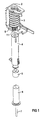
- the overcurrent release 1 shows the essential components of an overcurrent release 1 is shown in an exploded view for Circuit breakers for switching and protecting motors and other consumers.
- the overcurrent release 1 is essentially a U-shaped yoke 2, a coil winding 3, a coil former 4, an armature 5, a pole 6 with an associated plunger 7 and an adjustment ring 8 composed.
- the overcurrent release 1 in the assembled state in which the coil winding 3 on the coil former 4th is threaded, the coil winding 3 between the two legs of the U-shaped yoke 2 is arranged and the bobbin 4 through an opening in the upper leg of the Jokes 2 protrude through.
- the armature 5 and the pole 6 are located itself in the cavity of the cylindrical bobbin 4, so that in FIG. 2, only the plunger 7 from the coil body 4 at the bottom protrudes.
- the adjustment ring 8 is arranged between the lower leg of the yoke 2 and the Coil winding 3. He owns one pointing to the last turn 9, to the winding wire pitch adapted area 10 and thus forms a large area Support of the coil winding 3.
- Adjustment ring 8 On the inside is the Adjustment ring 8 provided with teeth, not shown here, which engage teeth on the bobbin 4.
- teeth By twisting of the adjustment ring 8 can the coil winding 3 exactly to the air gap between the armature 5 and the pole 2 in the axial direction be positioned.
- the adjustment ring 2 as a spacer acts between the coil winding and the yoke 2 is the The coil winding is thus secured against shifting.
- the said Internal teeth prevent unintentional turning back of the adjustment ring 8.
- the outer circumference is the Adjustment ring 8 provided with a toothing 11, the one easy adjustment by hand or by machine through a manufacturing facility allows.
Landscapes
- Physics & Mathematics (AREA)
- Electromagnetism (AREA)
- Breakers (AREA)
- Electromagnets (AREA)
Claims (5)
- Discontacteur à déclenchement par surintensité de courant, comprenant une culasse (2) en forme de U, un enroulement de bobine (3), un pôle (6) et une palette mobile (5), un entrefer existant entre le pôle (6) et la palette mobile(5), et l'enroulement de bobine (3) étant disposé entre les deux branches ou ailes de la culasse (2),
caractérisé en ce qu'entre l'enroulement de bobine (3) et l'une des deux branches de la culasse (2) est prévu un anneau d'ajustement (8), qui agit en tant qu'entretoise variable entre l'enroulement de bobine (3) et la culasse (2), et en ce que par rotation de l'anneau d'ajustement (8) il est possible de faire varier dans la direction axiale, la position de l'enroulement de bobine (3) par rapport à l'entrefer. - Discontacteur selon la revendication 1, caractérisé en ce que l'anneau d'ajustement (8) présente une surface (10) dirigée vers la dernière spire (9) de l'enroulement et adaptée à la pente du fil d'enroulement de l'enroulement de bobine (3).
- Discontacteur selon la revendication 1 ou 2, caractérisé en ce que l'enroulement de bobine (3) est disposé sur un corps de bobine (4).
- Discontacteur selon la revendication 3, caractérisé en ce que l'anneau d'ajustement (8) est pourvu sur son côté intérieur, de dents qui sont en prise avec des dents du corps de bobine (4).
- Discontacteur selon l'une des revendications précédentes, caractérisé en ce que l'anneau d'ajustement (8) est pourvu d'une denture extérieure (11).
Applications Claiming Priority (3)
| Application Number | Priority Date | Filing Date | Title |
|---|---|---|---|
| DE19836998 | 1998-08-14 | ||
| DE19836998 | 1998-08-14 | ||
| PCT/DE1999/002372 WO2000010187A1 (fr) | 1998-08-14 | 1999-08-03 | Dispositif avec enroulement de bobine pouvant etre positionne axialement |
Publications (2)
| Publication Number | Publication Date |
|---|---|
| EP1105900A1 EP1105900A1 (fr) | 2001-06-13 |
| EP1105900B1 true EP1105900B1 (fr) | 2002-10-30 |
Family
ID=7877609
Family Applications (1)
| Application Number | Title | Priority Date | Filing Date |
|---|---|---|---|
| EP99952244A Expired - Lifetime EP1105900B1 (fr) | 1998-08-14 | 1999-08-03 | Dispositif avec enroulement de bobine pouvant etre positionne axialement |
Country Status (5)
| Country | Link |
|---|---|
| US (1) | US6300853B1 (fr) |
| EP (1) | EP1105900B1 (fr) |
| CN (1) | CN1163932C (fr) |
| DE (1) | DE59903271D1 (fr) |
| WO (1) | WO2000010187A1 (fr) |
Cited By (1)
| Publication number | Priority date | Publication date | Assignee | Title |
|---|---|---|---|---|
| DE102006033717A1 (de) * | 2006-07-20 | 2008-01-31 | Siemens Ag | Justierbarer Kurzschlussauslöser |
Families Citing this family (4)
| Publication number | Priority date | Publication date | Assignee | Title |
|---|---|---|---|---|
| DE102008012149A1 (de) * | 2008-03-01 | 2009-09-03 | Abb Ag | Schaltgerät |
| CN102005344B (zh) * | 2010-11-19 | 2012-12-05 | 常熟开关制造有限公司(原常熟开关厂) | 框架式断路器的脱扣装置 |
| CN101986412B (zh) * | 2010-11-19 | 2012-11-07 | 常熟开关制造有限公司(原常熟开关厂) | 断路器的过载脱扣装置 |
| EP2544207B1 (fr) * | 2011-07-05 | 2017-03-29 | Siemens Aktiengesellschaft | Coupe-circuit avec connexion optimisée de la bobine |
Family Cites Families (2)
| Publication number | Priority date | Publication date | Assignee | Title |
|---|---|---|---|---|
| FR2626713B1 (fr) | 1988-01-28 | 1990-06-01 | Merlin Gerin | Declencheur electromagnetique a reglage du seuil de declenchement |
| US5793026A (en) * | 1997-04-14 | 1998-08-11 | Eaton Corporation | Magnetic trip assembly and circuit breaker incorporating same |
-
1999
- 1999-08-03 US US09/720,471 patent/US6300853B1/en not_active Expired - Fee Related
- 1999-08-03 CN CNB99809661XA patent/CN1163932C/zh not_active Expired - Fee Related
- 1999-08-03 EP EP99952244A patent/EP1105900B1/fr not_active Expired - Lifetime
- 1999-08-03 WO PCT/DE1999/002372 patent/WO2000010187A1/fr not_active Ceased
- 1999-08-03 DE DE59903271T patent/DE59903271D1/de not_active Expired - Fee Related
Cited By (2)
| Publication number | Priority date | Publication date | Assignee | Title |
|---|---|---|---|---|
| DE102006033717A1 (de) * | 2006-07-20 | 2008-01-31 | Siemens Ag | Justierbarer Kurzschlussauslöser |
| DE102006033717B4 (de) * | 2006-07-20 | 2009-06-04 | Siemens Ag | Justierbarer Kurzschlussauslöser |
Also Published As
| Publication number | Publication date |
|---|---|
| WO2000010187A1 (fr) | 2000-02-24 |
| CN1312949A (zh) | 2001-09-12 |
| DE59903271D1 (de) | 2002-12-05 |
| US6300853B1 (en) | 2001-10-09 |
| CN1163932C (zh) | 2004-08-25 |
| EP1105900A1 (fr) | 2001-06-13 |
Similar Documents
| Publication | Publication Date | Title |
|---|---|---|
| DE60000739T2 (de) | Steuervorrichtung zum öffnen und/oder zum schliessen, insbesondere für ein schaltgerät wie ein schutzschalter, und ein schutzschalter ausgerüstet mit dieser vorrichtung | |
| EP1063666B1 (fr) | Déclencheur électromagnétique | |
| DE3509203A1 (de) | Anordnung zum montieren eines bauelementes in einem ruecklauftransformator | |
| DE102007043869B4 (de) | Spulenträger und Joch eines elektromagnetischen Auslösers eines Schutzschaltgerätes, elektromagnetischer Auslöser sowie Schutzschaltgerät | |
| DE2062694A1 (de) | Fehlerstromschutzschalter | |
| WO2000010187A1 (fr) | Dispositif avec enroulement de bobine pouvant etre positionne axialement | |
| DE2458516A1 (de) | Elektromagnetische betaetigungseinrichtung | |
| EP2044605B1 (fr) | Declencheur a court-circuit reglable | |
| DE3110427A1 (de) | Ringkern-transformator-uebertrager-drossel | |
| DE1817496C3 (de) | Synchroübertrager | |
| DE3909742C2 (de) | Elektromagnet, insbesondere zur Betätigung der Unterbrecher einer Schaltvorrichtung | |
| DE202012104824U1 (de) | Vorrichtung zur Erfassung von Fehlerströmen | |
| DE2503691A1 (de) | Ringkernwandler | |
| DE4240031A1 (de) | Magnetauslöser für Fehlerstromschutzschalter | |
| DE3219368A1 (de) | Elektrischer leistungsschalter mit elektromagnetisch wirkendem ausloesemechanismus | |
| DE4344143B4 (de) | Elektromagnetischer Schnellauslöser für elektrische Schaltgeräte | |
| DE3744436C2 (fr) | ||
| DE2911810A1 (de) | Fehlerstrom-ausloeser | |
| DE102015207204A1 (de) | Kurzschluss-Auslösevorrichtung, Herstellungsverfahren für eine Magnetspule und elektromechanisches Schutzschaltgerät | |
| DE3343485C2 (de) | Impulstransformator für elektrische Zünder | |
| DE2951900A1 (de) | Ausloeser fuer fehlerstromschutzschalter | |
| DE882730C (de) | Elektrizitaetszaehler mit selbsttaetigem Maximalausschalter | |
| DE4320714A1 (de) | Dioden-Split-Hochspannungstransformator | |
| DE3625964A1 (de) | Transformator | |
| DE19944026A1 (de) | Auslöser für eine Fehlerstrom-Schutzvorrichtung und Verfahren zum Betrieb eines Auslösers |
Legal Events
| Date | Code | Title | Description |
|---|---|---|---|
| PUAI | Public reference made under article 153(3) epc to a published international application that has entered the european phase |
Free format text: ORIGINAL CODE: 0009012 |
|
| 17P | Request for examination filed |
Effective date: 20001129 |
|
| AK | Designated contracting states |
Kind code of ref document: A1 Designated state(s): AT BE CH CY DE DK ES FI FR GB GR IE IT LI LU MC NL PT SE |
|
| GRAG | Despatch of communication of intention to grant |
Free format text: ORIGINAL CODE: EPIDOS AGRA |
|
| GRAG | Despatch of communication of intention to grant |
Free format text: ORIGINAL CODE: EPIDOS AGRA |
|
| GRAH | Despatch of communication of intention to grant a patent |
Free format text: ORIGINAL CODE: EPIDOS IGRA |
|
| 17Q | First examination report despatched |
Effective date: 20020107 |
|
| GRAH | Despatch of communication of intention to grant a patent |
Free format text: ORIGINAL CODE: EPIDOS IGRA |
|
| GRAA | (expected) grant |
Free format text: ORIGINAL CODE: 0009210 |
|
| AK | Designated contracting states |
Kind code of ref document: B1 Designated state(s): DE FR IT |
|
| REF | Corresponds to: |
Ref document number: 59903271 Country of ref document: DE Date of ref document: 20021205 |
|
| ET | Fr: translation filed | ||
| PLBE | No opposition filed within time limit |
Free format text: ORIGINAL CODE: 0009261 |
|
| STAA | Information on the status of an ep patent application or granted ep patent |
Free format text: STATUS: NO OPPOSITION FILED WITHIN TIME LIMIT |
|
| 26N | No opposition filed |
Effective date: 20030731 |
|
| PG25 | Lapsed in a contracting state [announced via postgrant information from national office to epo] |
Ref country code: IT Free format text: LAPSE BECAUSE OF NON-PAYMENT OF DUE FEES Effective date: 20050803 |
|
| PGFP | Annual fee paid to national office [announced via postgrant information from national office to epo] |
Ref country code: FR Payment date: 20060809 Year of fee payment: 8 |
|
| PGFP | Annual fee paid to national office [announced via postgrant information from national office to epo] |
Ref country code: DE Payment date: 20061023 Year of fee payment: 8 |
|
| REG | Reference to a national code |
Ref country code: FR Ref legal event code: ST Effective date: 20080430 |
|
| PG25 | Lapsed in a contracting state [announced via postgrant information from national office to epo] |
Ref country code: DE Free format text: LAPSE BECAUSE OF NON-PAYMENT OF DUE FEES Effective date: 20080301 |
|
| PG25 | Lapsed in a contracting state [announced via postgrant information from national office to epo] |
Ref country code: FR Free format text: LAPSE BECAUSE OF NON-PAYMENT OF DUE FEES Effective date: 20070831 |