EP1106276A2 - Outil de presse pour sertir des corps creux a symetrie de rotation - Google Patents
Outil de presse pour sertir des corps creux a symetrie de rotation Download PDFInfo
- Publication number
- EP1106276A2 EP1106276A2 EP00122751A EP00122751A EP1106276A2 EP 1106276 A2 EP1106276 A2 EP 1106276A2 EP 00122751 A EP00122751 A EP 00122751A EP 00122751 A EP00122751 A EP 00122751A EP 1106276 A2 EP1106276 A2 EP 1106276A2
- Authority
- EP
- European Patent Office
- Prior art keywords
- press
- control
- bodies
- pressing
- degrees
- Prior art date
- Legal status (The legal status is an assumption and is not a legal conclusion. Google has not performed a legal analysis and makes no representation as to the accuracy of the status listed.)
- Withdrawn
Links
Images



Classifications
-
- B—PERFORMING OPERATIONS; TRANSPORTING
- B25—HAND TOOLS; PORTABLE POWER-DRIVEN TOOLS; MANIPULATORS
- B25B—TOOLS OR BENCH DEVICES NOT OTHERWISE PROVIDED FOR, FOR FASTENING, CONNECTING, DISENGAGING, OR HOLDING
- B25B27/00—Hand tools, specially adapted for fitting together or separating parts or objects whether or not involving some deformation, not otherwise provided for
- B25B27/02—Hand tools, specially adapted for fitting together or separating parts or objects whether or not involving some deformation, not otherwise provided for for connecting objects by press fit or detaching same
- B25B27/10—Hand tools, specially adapted for fitting together or separating parts or objects whether or not involving some deformation, not otherwise provided for for connecting objects by press fit or detaching same inserting fittings into hoses
-
- B—PERFORMING OPERATIONS; TRANSPORTING
- B21—MECHANICAL METAL-WORKING WITHOUT ESSENTIALLY REMOVING MATERIAL; PUNCHING METAL
- B21D—WORKING OR PROCESSING OF SHEET METAL OR METAL TUBES, RODS OR PROFILES WITHOUT ESSENTIALLY REMOVING MATERIAL; PUNCHING METAL
- B21D39/00—Application of procedures in order to connect objects or parts, e.g. coating with sheet metal otherwise than by plating; Tube expanders
- B21D39/04—Application of procedures in order to connect objects or parts, e.g. coating with sheet metal otherwise than by plating; Tube expanders of tubes with tubes; of tubes with rods
- B21D39/048—Application of procedures in order to connect objects or parts, e.g. coating with sheet metal otherwise than by plating; Tube expanders of tubes with tubes; of tubes with rods using presses for radially crimping tubular elements
-
- B—PERFORMING OPERATIONS; TRANSPORTING
- B21—MECHANICAL METAL-WORKING WITHOUT ESSENTIALLY REMOVING MATERIAL; PUNCHING METAL
- B21J—FORGING; HAMMERING; PRESSING METAL; RIVETING; FORGE FURNACES
- B21J13/00—Details of machines for forging, pressing, or hammering
- B21J13/02—Dies or mountings therefor
- B21J13/03—Die mountings
-
- B—PERFORMING OPERATIONS; TRANSPORTING
- B21—MECHANICAL METAL-WORKING WITHOUT ESSENTIALLY REMOVING MATERIAL; PUNCHING METAL
- B21J—FORGING; HAMMERING; PRESSING METAL; RIVETING; FORGE FURNACES
- B21J7/00—Hammers; Forging machines with hammers or die jaws acting by impact
- B21J7/02—Special design or construction
- B21J7/14—Forging machines working with several hammers
-
- B—PERFORMING OPERATIONS; TRANSPORTING
- B30—PRESSES
- B30B—PRESSES IN GENERAL
- B30B7/00—Presses characterised by a particular arrangement of the pressing members
- B30B7/04—Presses characterised by a particular arrangement of the pressing members wherein pressing is effected in different directions simultaneously or in turn
-
- H—ELECTRICITY
- H01—ELECTRIC ELEMENTS
- H01R—ELECTRICALLY-CONDUCTIVE CONNECTIONS; STRUCTURAL ASSOCIATIONS OF A PLURALITY OF MUTUALLY-INSULATED ELECTRICAL CONNECTING ELEMENTS; COUPLING DEVICES; CURRENT COLLECTORS
- H01R43/00—Apparatus or processes specially adapted for manufacturing, assembling, maintaining, or repairing of line connectors or current collectors or for joining electric conductors
- H01R43/04—Apparatus or processes specially adapted for manufacturing, assembling, maintaining, or repairing of line connectors or current collectors or for joining electric conductors for forming connections by deformation, e.g. crimping tool
- H01R43/058—Crimping mandrels
- H01R43/0585—Crimping mandrels for crimping apparatus with more than two radially actuated mandrels
Definitions
- Workpieces with cross sections are in shape under "rotationally symmetrical" of circles and regular polygons such as hexagonal and octagonal profiles to understand.
- the workpiece outer surfaces can be in the axial direction straight, conical, domed (barrel-shaped) or graded. Such workpiece surfaces can be trained accordingly the - preferably exchangeable - press jaws taken into account become.
- a special area of application for which the subject of the invention the combination of high-strength metal is particularly suitable (e.g. steel) existing hose fittings with flexible hose lines.
- the hose line consists essentially of one Hose piece, over the ends of which thick-walled compression sleeves are pushed become. Nipples are plugged into the ends, with fittings are provided, e.g. those with internal or external threads, flange plates, Pipe bends, elbows, pipe branches etc., which from the Protrude hose ends.
- the inner parts support the hose walls during the Pressing process from the inside.
- the compression sleeves are the shell diameters from the press jaws to the desired Final diameter reduced, but not only large press paths are to be covered, but also the pressing forces increase progressively.
- the pressing processes in small and large series production must be included high dimensional and repeat accuracy because the Hose lines, the pressures up to 1000 bar (100 MPa) and above have to endure, very often are safety-relevant components, their failure and failure cause immense costs and environmental damage can, and last but not least, people are at risk.
- hose lines due to the constant progress of Technology is becoming more complicated to shape.
- Increasingly compact machines and systems that are in progress reduce the installation volume of Hose lines, so that their designers are always new See problems confronted in the narrowest spaces and in accordance with regulations install properly functioning hose lines.
- Modern Computer-controlled bending machines are an essential part of this Become help if it makes complicated, quick, precise and inexpensive Multi-bend pipe bends are economical even in small series can be produced.
- the pipe bends can also be act those that have a bending angle of 180 degrees with the smallest possible Possess bending radius. Such bending radii are the same, for example the pipe diameter.
- the constriction path i.e. the diameter difference and after pressing
- the constriction path is divided into only four compression zones, which are between the pressing surfaces of the press jaws.
- the material of the compression sleeve in these areas so compressed that their Wall thickness increases. This growth can only be done internally, because the closing press jaws grow outwards prevent.
- the local compression in four-jaw systems often so large that the inner tube material including it Textile or steel reinforcement is destroyed.
- the Compression path on the circumference is calculated from the press path x 3.14, is 25.12 mm in both cases. Spread over four compression zones This results in 6.28 mm per compression zone, distributed over eight compression zones this results in only 3.14 mm per compression zone.
- the synchronization takes place in that the four inner press jaws on their outer End in a mirror-symmetrical arrangement depending on their direction of movement have two control surfaces with an opening angle of 135 degrees, and that the outer control body on their inner sides two complementary thereto Have control surfaces. Due to the lateral drive of the outer Control bodies can not large because of their tendency to tilt radial pressing forces are generated and transmitted. This press die is above all not divisible, so that no complicated shaped and / or bulky workpieces can be inserted.
- EP-A-0 539 787 describes a pressing tool as described at the beginning Genus with outer and inner control bodies known, that too has eight pressing surfaces, so that a significantly more uniform pressing process with reduced edge pressures.
- the planes of symmetry two of the inner control bodies run in the direction of the press stroke and the planes of symmetry of the other two internal control bodies perpendicular to this. This covers the last two inner control body a possible parting line of the press tool, the consequently, it is also not divisible. Such a division that the Bulky hose fittings would be impossible to insert described, still planned or possible.
- the Press stroke in a ratio of 1: 1 to the radial inward movement the pressing surfaces is transferred, so that a corresponding strong press drive is required.
- DE-C-19814 474 is also a pressing tool at the beginning described genus known, which has eight pressing surfaces, so that a significantly more uniform pressing process with reduced edge pressures he follows.
- the control surfaces of the two outer, in the stroke direction of the Press drive movable control body are angled several times formed, and two transverse to this inner control body have been replaced by four pressure pieces, the pairs above and are arranged below a parting line to two tool halves create that can be spread far apart to insert to allow bulky hose fittings.
- This design requires but with a variety of intricately shaped moving parts numerous sliding surfaces that must be machined to a high quality. Out of it there are corresponding manufacturing costs.
- the press stroke in a ratio of 1: 1 to the radial Inward movement of the pressing surfaces is transmitted, so that a corresponding strong press drive is required.
- the invention is therefore based on the object of a pressing tool Specify the type described above, the lower driving forces required, is simpler in construction and a lower number of high quality has to be machined sliding surfaces, so that it can be manufactured more cost-effectively is. Furthermore, the conditions are to be created for that the pressing tool in special cases also bulky for insertion Hose fittings or other bulky workpieces can be divided.
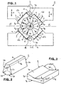
- Figure 1 shows a front view of a first embodiment of a Press tool 1 in the direction of the tool axis A in two operating positions, to the left of a plane of symmetry E are the pressing jaws 2 spread in a position immediately before the start of a pressing process and on the right the press jaws 2 are shown in the closed state.
- the Press jaws themselves are shown more clearly in FIG. 2.
- the press axis A lies in the plane of symmetry E.
- Two outer control bodies 3 and 4 have pairs of control surfaces 5, which under are at an angle of 90 degrees to each other, with the bisector lie in the plane of symmetry E. Wear the control surfaces 5 sliding pads 6, preferably from a self-lubricating and interchangeable storage material. Regarding the kinematics of the system however, reference is made to the control surfaces 5.
- the upper outer control body 3 is in Movable in the direction of arrows 8, namely by means of Figure 13 will be explained in more detail.
- the lower outer control body is arranged stationary, however the arrangement can be in any Space position operated, for example, also in an overhead position. In The spreading springs are visible in FIG. 1, but not numbered.
- the location of the System symmetry level E and the individual symmetry levels E1, E2, E3 and E4 of the inner control body 7 are for the kinematics of the Systems of crucial importance.
- the press jaws are "on block” driven, i.e. they touch flat at the end of their radial pressing paths. This has the advantage that in the event of failure of the one described below Stroke limitation the pressing tool may be damaged or destroyed can.
- FIG. 2 shows a single press jaw 2 in a perspective view, and this press jaw 2 consists of a mirror-symmetrical, Approximately prismatic body with a pressing surface 9, which is a partial cylinder surface is formed, two wedge-shaped at an angle of 45 degrees mutually arranged side surfaces 2a and 2b, two end surfaces 2c and has two flat control surfaces 2d and 2e, which are at an angle of 135 degrees to each other.
- the side surfaces 2a and 2b run therefore perpendicular to the immediately adjacent control surfaces 2d or 2e.
- the press surface 9 can also be part of an interchangeable press jaw attachment 9a, which is indicated by dashed lines.
- FIG. 3 shows one of the four inner control bodies 7 in perspective Representation, namely its envelope surface has the shape of a on five sides flat cuboid, the sixth side of which is arranged in mirror symmetry carries two flat inner control surfaces 7a and 7b, which under one Angles of 135 degrees to each other are arranged.
- the opposite Side is designed as an outer sliding surface 7c, and the control body 7 ends in two end faces 7d, of which only one is numbered.
- the right angle exposed outer sides running to the outer sliding surfaces 7c 7e are also for creating space for accommodation of angled parts of the hose fittings of large Importance.
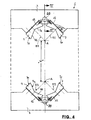
- FIG. 4 shows the subject of FIG. 1 in an expanded form Condition and without the press jaws 2.
- This figure also shows the enormously large possible opening path "w" of the press tool and thus the possibility of inserting bulky workpieces and easy Replacing the press jaws or press jaw sets according to FIGS. 7 and 8.
- FIG. 5 shows a top view of the lower half of the object of FIG. 1 with an inserted combination of a pressure hose 13, a compression sleeve 14 and a 180-degree elbow 15 with screw 16 in dash-dotted lines.
- the relationship of the inner Radius of curvature R to the pipe diameter is only slightly more than e.g. 1.5.
- the small depth T of the press tool also contributes to this 1 at.
- the combinations described are with the radial presses not to process the state of the art.
- the pressure hose 13 is on the operating side, and the whole arrangement is - with the exception of the pipe bend 15 - concentric.
- the illustration shows in connection with Figures 1 and 9 that the new press tool because of the presence of free spaces 10 and 11 the processing of such complicated hose-fitting combinations enables.
- FIG. 6 shows a section through the object from FIG. 4 along Line VI-VI in connection with part 17 of a press jaw insert before it is locked.
- Figures 7 and 8 show a front and a side view with the two parts 17 and 22 of a press jaw insert 23 in the open state.
- Eight press jaws 2 are radially displaceable between four ring sectors 24 and 25 arranged, namely a group of three between the upper ring sectors 24 and a group of five between the lower Ring sectors 25.
- the press jaw insert 23 can be divided and can linearly almost any distance apart.
- the bracket and radial guidance of the individual press jaws 2 is done radially to the axis A extending slots 26 and axially parallel guide bolts 27.
- each other locking pins 21 are in Threaded holes in the outer surfaces 28 of the top and lowest press jaw 2 attached. Holes not numbered are used for Inclusion of spreading springs 30, in the area of parting lines 31 between the press jaw insert parts 17 and 22 guide pin 29 connect. These guide pins 29 engage when the pressing jaw insert parts are closed 17 and 22 or the parting lines 31 in complementary Recesses in the opposing press jaws 2.
- the Joints 31 between the ring sectors 24 and 25 run below Angles of 135 or 225 degrees.
- press jaw set 23 cannot be divisible must, but for pressing simpler, in particular more straightforward, Hose-fitting combinations can also be undivided.
- the ring sectors 24 and 25 each form one-piece rings. It it should also be emphasized that the arrangement in any position can be operated, for example also in an upside-down position Figures 7 and 8.
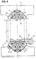
- Figures 9 and 10 show the subject of Figure 1 with the press jaw insert parts 17 and 22 according to FIGS. 7 and 8 in an expanded form and in the closed state immediately before initiation a pressing process.
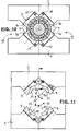
- Figure 11 shows the subject of Figure 4 with four adapter pieces 32 for the use of smaller press jaw insert parts 17 and 22 analogous to the figures 7 and 8.
- the octagonal envelope surface of the press jaws 2 be significantly reduced in diameter, i.e. it can for pressing of smaller hose fittings, significantly smaller press jaw inserts can be used, which makes the cost of the press jaws noticeable decreased.
- the same radial press is exemplary both for pressing hose fittings with one Outside diameter of 80 mm as well as with an outside diameter of only 10 mm can be used.
- the press jaws do not have to are replaced individually, but only one-piece or split press jaw inserts, usually with an appropriate label are provided for the final press diameter.
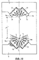
- Figure 12 shows a variant of the object of Figure 9, but with four press jaws according to Figure 2 and four inner control bodies 33, which Units from a press jaw 2 according to Figure 2 and an inner Control body 7 according to Figure 3 exist.
- Such an internal control body 33 is shown in FIG. 14.
- the stand at an angle of 45 degrees to each other and a ledge 33d are two control surfaces in a mirror-symmetrical arrangement 33a and 33b are available, the opening angle of which is 135 degrees is.
- an outer sliding surface 33g analogous to the sliding surface 7c in Figure 3. Die exposed outer sides perpendicular to this sliding surface 33g 33c are also for creating space for the Accommodation of angled parts of the hose fittings from great importance.
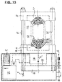
- Figure 13 shows a complete radial press with a press tool 9 in the open state and with the required drive devices.
- the outer control bodies 3 and 4 can be in trusses 34 and 35 can be inserted, which is indicated by dashed lines, or they can be made in one piece with the trusses 34 and 35.
- the upper cross member 34 two parallel tie rods 36 are firmly connected, which also specify the drive direction.
- the tie rods 36 are displaceable through the lower traverse 35, which also serves as a press table can be referred to, and below a drive cylinder 37 from which a piston rod 38 protrudes, with a further cross member 39 connected in which the lower ends of the tie rods 36 are fixed.
- the arrangement shown in Figure 13 has the advantage that the workpiece its position during the pressing process not or only insignificantly changed.
Landscapes
- Engineering & Computer Science (AREA)
- Mechanical Engineering (AREA)
- Manufacturing & Machinery (AREA)
- Press Drives And Press Lines (AREA)
- Automatic Assembly (AREA)
- Lining Or Joining Of Plastics Or The Like (AREA)
- Hand Tools For Fitting Together And Separating, Or Other Hand Tools (AREA)
Applications Claiming Priority (2)
| Application Number | Priority Date | Filing Date | Title |
|---|---|---|---|
| DE19958103A DE19958103C1 (de) | 1999-12-02 | 1999-12-02 | Preßwerkzeug zum Verpressen von rotationssymmetrischen Hohlkörpern |
| DE19958103 | 1999-12-02 |
Publications (2)
| Publication Number | Publication Date |
|---|---|
| EP1106276A2 true EP1106276A2 (fr) | 2001-06-13 |
| EP1106276A3 EP1106276A3 (fr) | 2003-05-21 |
Family
ID=7931176
Family Applications (1)
| Application Number | Title | Priority Date | Filing Date |
|---|---|---|---|
| EP00122751A Withdrawn EP1106276A3 (fr) | 1999-12-02 | 2000-10-19 | Outil de presse pour sertir des corps creux a symetrie de rotation |
Country Status (2)
| Country | Link |
|---|---|
| EP (1) | EP1106276A3 (fr) |
| DE (1) | DE19958103C1 (fr) |
Cited By (9)
| Publication number | Priority date | Publication date | Assignee | Title |
|---|---|---|---|---|
| WO2004087349A1 (fr) * | 2003-04-04 | 2004-10-14 | Op S.R.L. | Pince porte-outil perfectionnee pour presse radiale |
| EP1510269A1 (fr) * | 2003-08-27 | 2005-03-02 | Peter Dipl.-Ing. Schröck | Presse radiale pour sertir des corps creux à symétrie de rotation |
| WO2007012411A1 (fr) * | 2005-07-26 | 2007-02-01 | Punz Tec Srl | Presse universelle servant a deformer des manchons-raccords et a d'autres usages |
| WO2007093891A1 (fr) * | 2006-02-14 | 2007-08-23 | Eaton Corporation | Appareil de sertissage par replis avec une structure support comprenant une premiere et une seconde parties |
| WO2007093896A1 (fr) * | 2006-02-14 | 2007-08-23 | Eaton Corporation | Appareil de sertissage par replis et procedes de sertissage par replis avec des arretoirs |
| CN100542708C (zh) * | 2005-08-08 | 2009-09-23 | 本田技研工业株式会社 | 管材成形装置及管材成型方法 |
| IT201600094444A1 (it) * | 2016-09-20 | 2018-03-20 | Kgr Spa | Attrezzatura d’aggraffatura per aggraffare elementi di raccordo su tubi flessibili |
| FR3148873A1 (fr) * | 2023-05-19 | 2024-11-22 | Safran Electrical Components | Matrice de sertissage circulaire et procédé de sertissage |
| WO2025195981A1 (fr) * | 2024-03-18 | 2025-09-25 | Uniflex-Hydraulik Gmbh | Presse radiale |
Families Citing this family (13)
| Publication number | Priority date | Publication date | Assignee | Title |
|---|---|---|---|---|
| AUPQ886200A0 (en) | 2000-07-19 | 2000-08-10 | Betaswage Pty Ltd | Hydraulic swage press |
| US6484552B1 (en) * | 2000-12-16 | 2002-11-26 | Eaton Aeroquip, Inc. | Hinged die cage assembly |
| ITBS20010040U1 (it) * | 2001-04-23 | 2002-10-23 | Op Srl | Pressa radiale per la raccordatura di tubi flessibili oleodinamici |
| DE10150999C2 (de) * | 2001-10-16 | 2003-08-07 | Peak Werkstoff Gmbh | Verfahren zum Profilieren der äußeren Umfangsfläche von Zylinderlaufbuchsen |
| DE10237406A1 (de) * | 2002-08-12 | 2004-03-11 | Mapress Gmbh & Co. Kg | Presswerkzeug |
| DE20309747U1 (de) * | 2003-06-25 | 2003-09-11 | V-Team American Bikes + Products GmbH, 49479 Ibbenbüren | Vorrichtung zum Umformen von rohrförmigem Halbzeug |
| EP1745869A3 (fr) | 2005-07-22 | 2008-04-23 | Peter Dipl.-Ing. Schröck | Presse radiale pour le sertissage de corps creux à symétrie de révolution |
| DE102005034260B3 (de) * | 2005-07-22 | 2006-07-27 | Schröck-Horn, Ursula | Radialpresse zum Verpressen von rotationssymmetrischen Hohlkörpern |
| US7797979B2 (en) | 2006-02-14 | 2010-09-21 | Eaton Corporation | Crimping apparatus including a tool for supporting a plurality of crimping members |
| DE102009001949B4 (de) * | 2009-03-27 | 2011-02-24 | Wezag Gmbh Werkzeugfabrik | Gesenkhälfte und Presswerkzeug |
| DE102011052852A1 (de) * | 2011-08-19 | 2013-02-21 | Gustav Klauke Gmbh | Pressvorrichtung |
| EP2786817B1 (fr) * | 2013-04-05 | 2019-03-27 | Lillbacka Powerco OY | Système de machine de sertissage |
| CN110126328B (zh) * | 2019-06-17 | 2024-07-16 | 博众精工科技股份有限公司 | 石墨烯挤压机构 |
Family Cites Families (6)
| Publication number | Priority date | Publication date | Assignee | Title |
|---|---|---|---|---|
| GB1318880A (en) * | 1969-10-09 | 1973-05-31 | Dunlop Holdings Ltd | Swaging tools |
| JPS60141456A (ja) * | 1983-12-28 | 1985-07-26 | Toyoda Gosei Co Ltd | 挟持装置 |
| DE9007414U1 (de) * | 1990-04-12 | 1991-07-18 | Dischler, Helmut, Dipl.-Ing., 4040 Neuss | Preßwerkzeug |
| DE4130008A1 (de) * | 1991-09-10 | 1993-03-11 | Hewing Gmbh | Presswerkzeug zum aufpressen eines zylindrischen pressteils oder eines einen zylindrischen abschnitt aufweisenden pressteils auf ein rundprofil, insbesondere eine rohrleitung |
| DE4135465A1 (de) * | 1991-10-28 | 1993-04-29 | Schroeck Peter Dipl Ing Fh | Radialpresse mit zwei radial gegeneinander beweglichen pressenjochen |
| DE19814474C1 (de) * | 1998-04-01 | 1999-07-08 | Peter Dipl Ing Schroeck | Radialpreßwerkzeug für die Verformung rotationssymmetrischer Werkstücke |
-
1999
- 1999-12-02 DE DE19958103A patent/DE19958103C1/de not_active Expired - Fee Related
-
2000
- 2000-10-19 EP EP00122751A patent/EP1106276A3/fr not_active Withdrawn
Cited By (12)
| Publication number | Priority date | Publication date | Assignee | Title |
|---|---|---|---|---|
| WO2004087349A1 (fr) * | 2003-04-04 | 2004-10-14 | Op S.R.L. | Pince porte-outil perfectionnee pour presse radiale |
| CN100493766C (zh) * | 2003-04-04 | 2009-06-03 | Op有限公司 | 用于径向压力机的改进的工具座夹具 |
| US7553268B2 (en) | 2003-04-04 | 2009-06-30 | Op S.R.L. | Tool holding clamp for radial presses |
| EP1510269A1 (fr) * | 2003-08-27 | 2005-03-02 | Peter Dipl.-Ing. Schröck | Presse radiale pour sertir des corps creux à symétrie de rotation |
| WO2007012411A1 (fr) * | 2005-07-26 | 2007-02-01 | Punz Tec Srl | Presse universelle servant a deformer des manchons-raccords et a d'autres usages |
| CN100542708C (zh) * | 2005-08-08 | 2009-09-23 | 本田技研工业株式会社 | 管材成形装置及管材成型方法 |
| WO2007093891A1 (fr) * | 2006-02-14 | 2007-08-23 | Eaton Corporation | Appareil de sertissage par replis avec une structure support comprenant une premiere et une seconde parties |
| WO2007093896A1 (fr) * | 2006-02-14 | 2007-08-23 | Eaton Corporation | Appareil de sertissage par replis et procedes de sertissage par replis avec des arretoirs |
| IT201600094444A1 (it) * | 2016-09-20 | 2018-03-20 | Kgr Spa | Attrezzatura d’aggraffatura per aggraffare elementi di raccordo su tubi flessibili |
| EP3296035A1 (fr) * | 2016-09-20 | 2018-03-21 | KGR S.p.A. | Appareil de sertissage pour sertir des raccords de tuyaux sur des tuyaux flexibles |
| FR3148873A1 (fr) * | 2023-05-19 | 2024-11-22 | Safran Electrical Components | Matrice de sertissage circulaire et procédé de sertissage |
| WO2025195981A1 (fr) * | 2024-03-18 | 2025-09-25 | Uniflex-Hydraulik Gmbh | Presse radiale |
Also Published As
| Publication number | Publication date |
|---|---|
| EP1106276A3 (fr) | 2003-05-21 |
| DE19958103C1 (de) | 2001-03-01 |
Similar Documents
| Publication | Publication Date | Title |
|---|---|---|
| DE19958103C1 (de) | Preßwerkzeug zum Verpressen von rotationssymmetrischen Hohlkörpern | |
| DE10339291B3 (de) | Radialpresse zum Verpressen von rotationssymmetrischen Hohlkörpern | |
| DE2844475C2 (de) | Radialpresse für Werkstücke mit zylindrischer Außenfläche | |
| DE3925618C2 (de) | Vorrichtung zum Erzeugen von Längsnuten in einem Rohr | |
| EP4098432B1 (fr) | Presse radiale | |
| DE19814474C1 (de) | Radialpreßwerkzeug für die Verformung rotationssymmetrischer Werkstücke | |
| EP0539787A1 (fr) | Presse radiale avec deux culasses de presse radialement mobile entre elles | |
| DE102012102914B4 (de) | Spannvorrichtung für ein Werkstück oder Werkzeug | |
| DE2632748A1 (de) | Druckmittelbetaetigte schiebevorrichtung | |
| DE9216369U1 (de) | Preßwerkzeug | |
| DE4301124A1 (de) | Verfahren zum Montieren einer Zylinderbuchse in einem Grundkörper und hydraulische Maschine | |
| WO2002092258A1 (fr) | Dispositif de serrage hydromecanique servant notamment a l'extrusion laterale | |
| DE3238264A1 (de) | Rohrbiegemaschine mit biegedorn | |
| DE19924695C2 (de) | Expansionswerkzeug für Hohlkörper und Verfahren zu dessen Herstellung | |
| DE3235040C2 (de) | Presse zum Aufpressen von Hülsen, Kabelschuhen oder dergleichen | |
| DE2851944A1 (de) | Vorrichtung zur herstellung von rohrkoerpern mit axial aufeinanderfolgenden querwellen | |
| DE19944141C1 (de) | Radialpresse für das Verpressen von Hochdruckschläuchen mit rotationssymmetrischen Hohlkörpern von Schlaucharmaturen | |
| DE3230444C2 (de) | Bördelpresse für Metallrohre | |
| DE1934338A1 (de) | Vorrichtung zum Einbringen von Nuten in Metallteile | |
| DE3918800C1 (en) | Tube ends forming device - has tool head in form of pyramidal polygon, carrying movable segments | |
| EP0771615A1 (fr) | Appareil de sertissage pour sertissage radial de connexions de tubes | |
| DE3809369C2 (fr) | ||
| DE19543312C2 (de) | Preßvorrichtung zum radialen Verpressen von Leitungsverbindern | |
| DE1945757A1 (de) | Maschine zum Verformen eines Werkstueckes | |
| DE10140191B4 (de) | Schnellspannvorrichtung |
Legal Events
| Date | Code | Title | Description |
|---|---|---|---|
| PUAI | Public reference made under article 153(3) epc to a published international application that has entered the european phase |
Free format text: ORIGINAL CODE: 0009012 |
|
| AK | Designated contracting states |
Kind code of ref document: A2 Designated state(s): AT BE CH CY DE DK ES FI FR GB GR IE IT LI LU MC NL PT SE |
|
| AX | Request for extension of the european patent |
Free format text: AL;LT;LV;MK;RO;SI |
|
| PUAL | Search report despatched |
Free format text: ORIGINAL CODE: 0009013 |
|
| AK | Designated contracting states |
Designated state(s): AT BE CH CY DE DK ES FI FR GB GR IE IT LI LU MC NL PT SE |
|
| AX | Request for extension of the european patent |
Extension state: AL LT LV MK RO SI |
|
| STAA | Information on the status of an ep patent application or granted ep patent |
Free format text: STATUS: THE APPLICATION IS DEEMED TO BE WITHDRAWN |
|
| 18D | Application deemed to be withdrawn |
Effective date: 20030503 |