EP1106357B1 - Verfahren und Drucker mit Fehlermaske - Google Patents
Verfahren und Drucker mit Fehlermaske Download PDFInfo
- Publication number
- EP1106357B1 EP1106357B1 EP00403350A EP00403350A EP1106357B1 EP 1106357 B1 EP1106357 B1 EP 1106357B1 EP 00403350 A EP00403350 A EP 00403350A EP 00403350 A EP00403350 A EP 00403350A EP 1106357 B1 EP1106357 B1 EP 1106357B1
- Authority
- EP
- European Patent Office
- Prior art keywords
- substrate
- voltage
- charge
- droplets
- nominal
- Prior art date
- Legal status (The legal status is an assumption and is not a legal conclusion. Google has not performed a legal analysis and makes no representation as to the accuracy of the status listed.)
- Expired - Lifetime
Links
- 238000000034 method Methods 0.000 title claims description 16
- 230000000873 masking effect Effects 0.000 title description 3
- 239000000758 substrate Substances 0.000 claims description 153
- 238000012937 correction Methods 0.000 claims description 34
- 238000013519 translation Methods 0.000 claims description 19
- 238000012986 modification Methods 0.000 claims description 2
- 230000004048 modification Effects 0.000 claims description 2
- 238000002347 injection Methods 0.000 claims 2
- 239000007924 injection Substances 0.000 claims 2
- 238000007639 printing Methods 0.000 description 77
- 230000007547 defect Effects 0.000 description 31
- 239000000976 ink Substances 0.000 description 24
- 230000006870 function Effects 0.000 description 15
- 238000011144 upstream manufacturing Methods 0.000 description 9
- 238000004364 calculation method Methods 0.000 description 7
- 239000003086 colorant Substances 0.000 description 7
- 238000010586 diagram Methods 0.000 description 5
- 230000000903 blocking effect Effects 0.000 description 4
- 238000001514 detection method Methods 0.000 description 4
- 239000006185 dispersion Substances 0.000 description 4
- 238000005259 measurement Methods 0.000 description 4
- 230000002441 reversible effect Effects 0.000 description 4
- 230000009897 systematic effect Effects 0.000 description 4
- 102100040160 Rabankyrin-5 Human genes 0.000 description 3
- 101710086049 Rabankyrin-5 Proteins 0.000 description 3
- 238000006073 displacement reaction Methods 0.000 description 3
- 238000001035 drying Methods 0.000 description 3
- 230000005484 gravity Effects 0.000 description 3
- 230000008901 benefit Effects 0.000 description 2
- 230000008859 change Effects 0.000 description 2
- 230000001186 cumulative effect Effects 0.000 description 2
- 239000002674 ointment Substances 0.000 description 2
- 238000009825 accumulation Methods 0.000 description 1
- 230000015572 biosynthetic process Effects 0.000 description 1
- 230000000295 complement effect Effects 0.000 description 1
- 238000013500 data storage Methods 0.000 description 1
- 230000008021 deposition Effects 0.000 description 1
- 238000013461 design Methods 0.000 description 1
- 230000005684 electric field Effects 0.000 description 1
- 230000001747 exhibiting effect Effects 0.000 description 1
- 230000006872 improvement Effects 0.000 description 1
- 238000007641 inkjet printing Methods 0.000 description 1
- 238000012423 maintenance Methods 0.000 description 1
- 239000011159 matrix material Substances 0.000 description 1
- 239000003607 modifier Substances 0.000 description 1
- 230000003287 optical effect Effects 0.000 description 1
- 230000008447 perception Effects 0.000 description 1
- 238000012545 processing Methods 0.000 description 1
- 238000011084 recovery Methods 0.000 description 1
- 230000009467 reduction Effects 0.000 description 1
- 238000005070 sampling Methods 0.000 description 1
- 230000001360 synchronised effect Effects 0.000 description 1
- 230000007704 transition Effects 0.000 description 1
- 210000001113 umbilicus Anatomy 0.000 description 1
Images




Classifications
-
- B—PERFORMING OPERATIONS; TRANSPORTING
- B41—PRINTING; LINING MACHINES; TYPEWRITERS; STAMPS
- B41J—TYPEWRITERS; SELECTIVE PRINTING MECHANISMS, i.e. MECHANISMS PRINTING OTHERWISE THAN FROM A FORME; CORRECTION OF TYPOGRAPHICAL ERRORS
- B41J29/00—Details of, or accessories for, typewriters or selective printing mechanisms not otherwise provided for
- B41J29/38—Drives, motors, controls or automatic cut-off devices for the entire printing mechanism
- B41J29/393—Devices for controlling or analysing the entire machine ; Controlling or analysing mechanical parameters involving printing of test patterns
-
- B—PERFORMING OPERATIONS; TRANSPORTING
- B41—PRINTING; LINING MACHINES; TYPEWRITERS; STAMPS
- B41J—TYPEWRITERS; SELECTIVE PRINTING MECHANISMS, i.e. MECHANISMS PRINTING OTHERWISE THAN FROM A FORME; CORRECTION OF TYPOGRAPHICAL ERRORS
- B41J2/00—Typewriters or selective printing mechanisms characterised by the printing or marking process for which they are designed
- B41J2/005—Typewriters or selective printing mechanisms characterised by the printing or marking process for which they are designed characterised by bringing liquid or particles selectively into contact with a printing material
- B41J2/01—Ink jet
- B41J2/07—Ink jet characterised by jet control
- B41J2/075—Ink jet characterised by jet control for many-valued deflection
- B41J2/08—Ink jet characterised by jet control for many-valued deflection charge-control type
-
- B—PERFORMING OPERATIONS; TRANSPORTING
- B41—PRINTING; LINING MACHINES; TYPEWRITERS; STAMPS
- B41J—TYPEWRITERS; SELECTIVE PRINTING MECHANISMS, i.e. MECHANISMS PRINTING OTHERWISE THAN FROM A FORME; CORRECTION OF TYPOGRAPHICAL ERRORS
- B41J2/00—Typewriters or selective printing mechanisms characterised by the printing or marking process for which they are designed
- B41J2/005—Typewriters or selective printing mechanisms characterised by the printing or marking process for which they are designed characterised by bringing liquid or particles selectively into contact with a printing material
- B41J2/01—Ink jet
- B41J2/07—Ink jet characterised by jet control
- B41J2/075—Ink jet characterised by jet control for many-valued deflection
- B41J2/08—Ink jet characterised by jet control for many-valued deflection charge-control type
- B41J2/085—Charge means, e.g. electrodes
-
- B—PERFORMING OPERATIONS; TRANSPORTING
- B41—PRINTING; LINING MACHINES; TYPEWRITERS; STAMPS
- B41J—TYPEWRITERS; SELECTIVE PRINTING MECHANISMS, i.e. MECHANISMS PRINTING OTHERWISE THAN FROM A FORME; CORRECTION OF TYPOGRAPHICAL ERRORS
- B41J2/00—Typewriters or selective printing mechanisms characterised by the printing or marking process for which they are designed
- B41J2/005—Typewriters or selective printing mechanisms characterised by the printing or marking process for which they are designed characterised by bringing liquid or particles selectively into contact with a printing material
- B41J2/01—Ink jet
- B41J2/21—Ink jet for multi-colour printing
- B41J2/2132—Print quality control characterised by dot disposition, e.g. for reducing white stripes or banding
Definitions
- the invention is in the field of ink jet printers in which ink drops are formed and electrically charged and then deflected to strike a printing substrate. It relates to a method for masking or reducing lineage defects and the printer applying such a method.
- a jet of pressurized ink ejected by a printing nozzle can be broken into a succession of individual drops each drop being individually loaded in a controlled manner. In the path of these drops thus individually charged, electrodes of constant potential deviate more or less drops according to the charge they have. If a drop is not to reach the printing substrate, its charge is controlled so that it is diverted to an ink recuperator.
- the operating principle of such inkjet printers is well known and is described for example in US-A-4 160 982. As described in this patent and shown in FIG. 1, such a printer comprises a reservoir 11 containing the electrically conductive ink 10 which is distributed by a distribution channel 13 to a drop generator 16.
- the role of the drop generator 16 is to form from the ink under pressure contained in the distribution channel 13 a set of individual drops. These individual drops are electrically charged by means of a charging electrode 20 supplied by a voltage generator 21. The charged drops pass through a space between two deflection electrodes 23, 24 and depending on their charge are more or less diverted. The least or no deviated drops are directed towards an ink recuperator 22 while the deviated drops are directed towards a substrate 27. The successive drops of a burst reaching the substrate 27 can thus be diverted towards an extreme low position, a extreme high position and successive intermediate positions, the set of drops of the salvo forming a vertical line of height ⁇ x substantially perpendicular to a direction of relative advance of the print head and the substrate.
- the print head is formed by the drop generator 16, the charging electrode 20, the deflection electrodes 23, 24 and the recuperator 22. This head is generally enclosed in a not shown cowling.
- the deflection movement printed to the drops loaded by the deflection electrodes 23, 24 is completed by a movement along a Y axis perpendicular to the X axis, between the print head and the substrate.
- the time elapsed between the first and the last drop of a salvo is very short. As a result, despite a continuous movement between the print head and the substrate, it can be considered that the substrate does not have moved relative to the print head during the time of a salvo.
- the bursts are fired at regular space intervals.
- the printing is done strip by strip the substrate having a motion intermittent feed in the X direction after each sweep.
- the relative movement of the print head and the substrate is called scanning movement.
- the scanning movement thus consists of a back and forth motion between a first edge of the substrate and a second edge of the substrate.
- the movement between one edge and the other edge of the substrate makes it possible to print on the fly a band of height L or quite often a part of the band of height ⁇ X, ⁇ X being most often a sub-multiple of L.
- the set of successively printed strips thus constitutes the pattern to be printed on the substrate.
- the substrate is advanced from the space between two webs or part of web for printing the next tape or web portion. Printing can be done just one way or the other way around the movement of the print head relative to the substrate.
- each inkjet prints a limited portion of the substrate.
- the drops may be continuously produced as described above in connection with FIG. 1. They may also be produced "on demand", that is to say only when they are necessary for the needs of the patient. 'impression. In this case, an unused ink recovery circuit is not necessary.
- the print pattern is defined by a digital file.
- This file can be formed using a scanner, a computer-assisted graphic design (CAD) palette, transmitted by means of a computer network for data exchange, or simply read from a digital data storage device read device (optical disk, CD-ROM).
- the digital file representing the colored pattern to be printed is first split into several bit patterns (or bitmap) for each of the inks.
- bit patterns or bitmap
- the case of the binary pattern is a non-limiting example; in some printers, the pattern to print is of type "contone", that is to say that each position can be printed by a number of drops variable from 1 to M. Part of the binary pattern is extracted from the file for each jets corresponding to the width of the band that will be printed.
- a storage memory of the cut digital pattern is represented in FIG. in tape, this storage memory containing the indications relating to a color.
- an intermediate memory 2 receives the data necessary for the printing of the band by said color.
- the descriptive data of the band to be printed are then introduced into a computer 3 of the charging voltages of the different drops which will form the band relative to this color. These data are introduced into the computer in the form of a succession of descriptions of the frames which together will constitute the band.
- the computer 3 drops charge voltages is often in the form of a dedicated integrated circuit.
- This calculator 3 calculates in real time the sequence of voltages to be applied to the charging electrodes 20 to print a given frame defined by its frame description, as loaded from the intermediate memory 2.
- a downstream electronic circuit 4, called a sequencer of drop charge ensures the synchronization of the charging voltages with, on the one hand, the moments of drop formation and, on the other hand, the relative advance of the print head and the substrate.
- the advance of the substrate with respect to the head is embodied by a frame clock whose signal is derived from the signal of an incremental encoder of position of the printing unit relative to the substrate.
- the sequencer 4 for charging the drops also receives a signal from a drop clock 6. This drop clock is synchronous with the control signal of the drop generator 16. It makes it possible to define the instants of transitions of the different applied charge voltages. with drops to differentiate their trajectories.
- the digital data from the drop charge sequencer 4 are converted into analog value by a digital analog converter 8.
- the data to be printed may not be in the form of binary files, but in the form of files containing words of several bits, to reflect the fact that each position of the substrate can receive several drops of ink of the same color.
- the main printing defects that are generated by all known printing systems are the defects relating to lineations in the direction of the relative movement of the print head relative to the substrate. This defect is reflected by the appearance of light or dark lines when printing by successive scans.
- defects can be in the space between two bands which should in principle be equal to the interval between adjacent drops of a frame, or within the same band, in the space delimiting the printed areas by different jets, or even inside the frame printed by a jet at the space between two adjacent drops of the frame.
- lineage defects can come either from defects specific to certain jets of the print head, it is then defects of mechanical or electrical origin, either of errors of positioning of the substrate, or of error of positioning between heads. of printing, or between jets of the same print head.
- Various solutions have been proposed to limit or eliminate lineage problems, but all of them result either in a limitation of the print rate, sometimes in a very high ratio with respect to the nominal print rate, or a redundancy of printheads and therefore a significant cost.
- a first type of The solution is based on fine mechanical adjustments of the position of the print heads, thanks to micrometric tables. This solution is both expensive, by the number of micrometric tables that are necessary, and often tedious, by trial and error it requires.
- Another type of common solution is to use a very high rate of overlap between neighboring drops, so as to avoid white lineages. These white lineages correspond to the lack of substrate coverage. Dark lineages are less visible and it is preferred to have a dark lineage defect rather than a white lineage defect.
- the solution of increasing the rate of overlap between adjacent drops is effective to compensate for defects within the same band and to some extent the lineage defects between bands but it has the disadvantage of requiring an amount of very high ink per unit area of the substrate and generates difficulties of drying or deformation of the substrate.
- a third type of solution for clearing lineage defects on scanning printers is to partially print the substrate during each scan. By multiplying the number of substrate scans, the total coverage of the substrate is obtained.
- This multi-pass printing exploits various strategies of interleaving the positions of the drops from the different jets.
- An example of interleaving of even and odd lines is given in US-A-4,604,631 issued to US Pat. RICOH company.
- An advantage of this solution often related to a high overlap ratio is that it allows a drying time of the substrate, but it results in the reduction of the printing rate by a factor ranging from 2 to 16.
- WO 97/06009 shows a printer where the value of the charge applied to the drops is set according to the speed of the substrate.
- the method according to the invention aims to hide some problems lineage without impact on the printing speed.
- the present invention does not require a high rate of overlapping drops. It achieves high print speeds with a relatively small number of print heads.
- a lineage defect in particular a white lineage defect appearing regularly. This defect is very perceptible to the eye when it is regular.
- an additional voltage of noise is superimposed on a nominal charge voltage of the drops, intended to give, relative to the nominal position of each drop, a real position exhibiting a random dispersion character. Thanks to this dispersion of the real position of every drop around its nominal position, the lineage fault no longer appears as a continuous straight line. It becomes less noticeable to the eye
- the invention therefore relates to a method of modifying the arrival position on a substrate of electrically charged drops of ink in a controllable and sequential manner by charging electrodes, the drops coming from a print head, the trajectories of drops being modifiable, by means of deflection electrodes, between N nominal positions a first position X 1 , a last position X N and N-2 intermediate positions, the N positions defining a frame in the form of a line segment parallel to a direction X of the substrate, characterized in that in superposition to a nominal voltage applied to the charging electrodes of the drops, an additional random algebraic voltage masking a possible defect lineage by dispersion of the actual position of each drop around of its nominal position.
- the average amplitude of this noise voltage will be a function of the rank j of the drop in the frame.
- the maximum amplitude of the additional noise voltage will be equal to a fraction less than 1 of the smallest difference between the nominal voltage Vj to be applied to the drop of rank j and the nominal voltage VJ + 1 or Vj-1 to apply to one of the two immediately adjacent drops in the weft printed pattern of rank j, ie the drops of rank j + 1 and rank j-1.
- a value of the average value of the mean value of the difference in voltages can be taken as the average value of the additional random voltage. nominal between two adjacent drops printed in the frame.
- the minimum amplitude of the additional noise voltage will be equal to the value of the voltage difference that can be obtained by varying the value of the least significant bit of an analog-digital converter whose output supplies a high voltage amplifier coupled to the charging electrodes of the drops.
- the amplitude of the additional noise voltage will correspond to a random digital value generated by a pseudo random number generation algorithm.
- the correspondence between the random digital value and the additional noise voltage will result from the application of this digital value to the digital to analog converter.
- the regular default of dark or white lineage will not appear or will appear less.
- the printer further comprises a detector of the position of a printed mark before each first frame of a tape, this detector providing a representative value of a difference between the real and nominal positions of the substrate and that the print control means comprise in in addition to a calculator of a forward translation dynamic correction voltage ⁇ of the substrate, this calculator determining a substrate forward dynamic translation correction voltage ⁇ for each drop of a burst according to its rank, this voltage of correction taking into account a difference value of the advance of the substrate delivered by means coupled to the detector and calculating a deviation value with respect to a nominal position, the dynamic translation correction correction voltage calculator ⁇ of the substrate being coupled to the drop charge fixing means, the drop charge fixing means taking into account the value of the substrate advance correction voltage generated by the dynamic translation correction voltage calculator ⁇ in advance of the substrate for modifying the charging voltage of each drop as a function of the forward dynamic translation correction voltage ⁇ of the substrate.
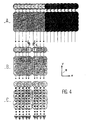
- Figure 3 is intended to explain what are the deviations caused by the additional noise algebraic voltage. For this, there is shown in different configurations on the plane of the substrate materialized by XY axes, 9 different nominal positions of drops of a frame drawn by a salvo of drops. In the example shown and to simplify the explanation, nine drops were taken, which has been represented in an excessively spaced manner.
- FIG. 3 A vision more This figure comprises the parts A, B and C.
- part A there are shown two successions of five frames each comprising nine drops numbered from 1 to 9. The drops are represented by circles whose surfaces partially overlap between frames and between drops of the same frame.
- One of the successions of five frames represented in part A is obtained during a first scan the other during a second scan for example, a forward scan and a reverse scan as shown by arrows on the three parts of Figure 4.
- Bet A the positions of the nine drops are in accordance with their nominal positions as it appears on the five consecutive frames and on a fictitious frame on which we carried the numbers of the drops.
- part B there is shown a single band also on five consecutive frames and a fictitious frame bearing the numbers of the positions of the drops.
- rank 5 drop was systematically displaced with respect to its position nominal to the drop of rank 4.
- drop of rank 6 was systematically displaced with respect to its nominal position towards the drop of rank 7.
- Each of the real and nominal positions of each of these two drops 5 and 6 is represented by a rhombus partly B.
- the differences d are such that the drops of rank 5 and 6 no longer overlap and are tangent to each other.
- part C of Figure 4 there is shown a succession of five frames for which the drops 5 and 6 have the same defect as that commented in conjunction with Part B.
- Part C the position of the drops of each frame is changed according to the invention by a random voltage added to the charging electrodes. This results in a position sounding. This sound breaks the regularity of the succession of white dots so that the defect is less visible.
- part B there is shown two frames. These two frames lie in the set of frames forming a band immediately following the band of frames represented in part A. Normally the bands A and B are spaced from each other by a distance equal to the equal distance. between two adjacent drops of a salvo.
- the defect of lineage between consecutive bands or within the same band may have the same origin consisting of a systematic shift of a drop relative to its nominal position, whether this drop is a first or last drop of a salve or an intermediate drop.
- the lack of lineage can have another origin. If the advance of the substrate with respect to the print head is not equal to the nominal advance, a lineage fault may appear or be increased by the difference between the nominal position of the substrate and its actual position.
- This addition of the invention relates to a positional deviation of a band due to a gap in the advance of the substrate.
- This correction concerns printers in which the substrate is advanced step by step after the printing of each strip.
- a first mark represented at A in FIG. 5 will be printed when printing a current band. This mark may consist of a single line printed by means of one or more drops of consecutive rank.
- the mark A is displaced and occupies the position shown in B in FIG. 5.
- the position in C of a mark is also represented. fictitious representing the nominal position that should have had the mark A in the absence of difference between the nominal position and the actual position.
- the C mark is not present on the substrate in a real way.
- the difference between the imaginary mark C and the mark in position B makes it possible to determine the difference ⁇ x between the nominal position marked at C and the actual position marked at B. This difference in the advance of the substrate will be compensated according to this aspect. of the invention by modifying the charge of the drops printed during the next strip.
- next strip will, like the printing of the current strip, have the impression of a next strip mark printed taking into account the actual advance of the substrate. It follows that the marks and the bands will be spaced apart from each other by their nominal spacing.
- Detection of the difference ⁇ x between the mark B and the nominal position C of the band that will be printed will be carried out by means of a sensor 12, for example a CCD sensor making it possible to measure this distance, for example by counting the the difference in number between a sensor element 12a which receives the mark when it is in the nominal position and a sensor element 12b which actually receives it.
- This sensor will preferably be placed facing the substrate and arranged so that its measurement field makes it possible to detect the mark with fairly wide tolerances.
- This sensor will preferably be a sensor of a determined light wavelength and will be completed by an emitter in the direction of the substrate of this determined wavelength.
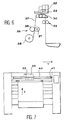
- FIGS. 6 and 7 are schematic diagrams of ink jet color pattern printers showing some of the features necessary to incorporate the invention.
- the system shown in FIGS. 6 and 7 corresponds to an architecture for printing large formats chosen solely as non-limiting examples.
- the printing is carried out by successive scans in the Y direction.
- the system uses, in a known manner, a substrate 27 from a reel 28, the unwinding of which is carried out upstream of a printing unit 29 by a pair 36 of rolls 37, 38 for driving in contact.
- a first cylinder 37 is motorized, a second cylinder 38 provides against pressure at the point of contact.
- the two cylinders 37, 38 pinch the substrate and drive it without slipping.
- the advance of the substrate 27 is controlled by an encoder, not shown because in itself known, of angular positions mounted on the axis of one of the cylinders. After each intermittent advance of the substrate, the printing zone thereof is kept flat on a printing table 30, located under the scanning path of the printing unit 29. This flat hold is ensured by means of a second drive system 39 located downstream of the printing unit.
- This second drive system 39 maintains a constant voltage of the substrate 27. Intermittent depression of the printing table is sometimes performed to improve the flatness of the substrate 27 in the printing area.
- the inkjet printing unit 29 is composed of several printing heads 25, such as those shown for example in FIG. 1, each head being fed by one of the primary color inks, from tanks 11 by means of an umbilicus or distribution channel 13.
- the different print heads 25 simultaneously print the substrate while it is stationary.
- the printing of a band is ensured by a scan in the Y direction of the printing unit.
- the scanning movement of the printing unit relative to the substrate is ensured by a belt 40 integral with the printing unit and driven by a motorized pulley 41.
- the guiding of the printing unit is ensured by known by a mechanical axis not shown.
- Each printhead prints a band of constant width L.
- the printheads can be shifted in the X direction of advance of the substrate so that a head does not necessarily print the same tape at the same time as another print head corresponding to a different ink color.
- the substrate is advanced by a spatial increment ⁇ X at most equal to the bandwidth L but which is more generally a sub-multiple of L for printing in multiple passes.
- the invention according to this embodiment has the particularity of being equipped with a detector 12 for detecting the actual advance of the substrate.
- the position of this detector 12 with respect to the substrate and to the printing heads is discussed below with reference to FIGS. 8 to 10.
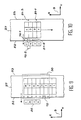
- FIG. 8 comprises parts A, B and C each corresponding to a phase of the print kinematics of a set of strips.
- the detector 12 is fixed, and fixed for example to a device for holding the translation axis of the printing heads 16.
- FIGS. 8 to 10 show four print heads 25, one for each of the colors, cyan marked C, magenta marked M, yellow marked Y and black marked K.
- the device for maintaining the translation axis has not been shown because its geometry is specific to each printer. In addition, this is an example. The skilled person will find or create a support for fixing the detector knowing that this detector must perform the functions that are described below.
- the detector must be able to detect a mark 51 printed by one of the print heads 25 between the left or right edge 53 of the substrate 27 and the beginning or the end respectively of the printed pattern.
- part A of FIG. 8 there is shown a first marked strip 1 printed while the print heads 25 move between a first edge 52, in the figure the left edge, and a second edge 53, in the figure the right edge of the substrate, as indicated by an arrow parallel to the scanning direction Y and perpendicular to the direction X of advance of the substrate 27.
- the detector 12 is placed at the edge of the substrate 27, in the vicinity of the printing head 25 situated in the second position in the set of heads.
- the second position is understood by counting the heads in the direction Y of advance of the substrate 27.
- the first head is the one which is the most upstream relative to the direction of travel of the substrate.
- the detector 12 is at a height relative to the lower substrate at the height of the lower parts of the print head so as to leave them the passage.
- the proximity of the substrate allows a better reading accuracy.
- the mark 51-1 is printed by the cyan head.
- This same cyan head then prints the strip 1 in the scanning direction indicated by an arrow in the Y direction.
- the heads 25 are in the position shown in dashed lines in the left-hand part of FIG. the heads 25 are in the position shown in solid lines to the right of the substrate 27.
- the substrate 27 is advanced one step.
- the mark 51-1 is in the field of the detector 12.
- the detector 12 detects a possible deviation of the advance of the substrate from the nominal advance, and the calculation means 34, 35 calculate corrections to be made to the voltages Charging the drops of the cyan head and the magenta head, so that the change in trajectory of the drops compensates for the gap in advance of the substrate.
- the magenta head prints the second color on the tape 1 and the cyan head prints the second tape then the mark 51-2.
- the heads 16 are found on the side of the first edge as shown in part B.
- the substrate is again advanced so that the mark 51-2 arrives in the field of the detector 12, as shown in part C in FIG. 8.
- the detector detects any deviation of the mark 51-2 from its nominal position.
- the mark 51-3 and the third band are printed by the upstream head cyan.
- the magenta head prints the second band with drop charge voltage corrections to account for the last gap value ⁇ x
- the yellow Y head prints the first band.
- the heads 25 are on the side of the second edge 53.
- the substrate is advanced.
- the detector detects any deviation of the 51-3 mark from its nominal position. A correction taking into account this difference is applied to load the drops of the black head which will print by superposition the first band, the yellow Y head which will print the second band and the magenta and cyan heads which will print respectively the third band and the mark 51-4 followed by the fourth band.
- the cycle thus continues modulo the number of juxtaposed print heads, for example four in the case shown in connection with FIG. 8.
- the kinematics which has just been described concerns an impression in which the heads print in the forward scan movement and in the reverse scan movement.
- the kinematics would be the same in the case of printing only by forward scanning, the advance of the substrate being done at the same time as the return movement of the heads towards the first edge 52.
- the motor control advance of the substrate may include a servo which takes into account the substrate advance gaps.
- This enslavement known to those skilled in the art, may be of the "proportional integral and derivative" type, that is to say that it takes into account the real differences, their accumulation and their variation over time in order to avoid drifts.
- the reading of the marks, the determination of the gap in advance of the substrate and the correction of the frames makes it possible at any moment to ensure the good superposition of the bands.
- the mark printed when printing a current band and which serves as a position reference for printing the next strip does not arrive in the field of the detector 12.
- the detector 12 will therefore reuse the mark that was used to print the current band with the same corrections, so that if we do not detect the blocking or near-blocking of substrate the next tape will print overlap on the previous tape.
- the printed pattern of even-rank marks is different from that of odd-numbered marks.
- Another case where the recognition of the current mark with respect to the next mark is interesting is the case where these two marks would be simultaneously visible on the detector 12, for example one on an upstream end portion of the detector and the other on an end portion downstream from the direction of movement of the substrate. This situation can arise if there is a cumulative difference in advance reaching a positive or negative value of half a nominal advance. In this case, the program will select the reference mark for printing the next tape.
- the program in the event of detection of a blocking or quasi-blocking may include triggering another substrate advance and then triggering an alert if a blockage is detected again, or on the contrary the immediate triggering of an alarm.
- the pattern of even and odd-rank band marks will be a function of the detector.
- the even and odd patterns will be distinguished from each other by the number of lines of one compared to the number of lines of the other, the difference between lines being such that each line is detected by a different sensor element. It could also be the same number of lines but with different spacings between lines corresponding to different numbers of the sensor elements detecting these lines.
- the sensor 12 comprises sensor elements arranged in a matrix manner, or if the sensor 12 is, as will be described later, movable in the X direction of the scan, the odd or even patterns may be distinguished, moreover, by variations in the scanning direction, for example, points for one and lines for the other or different distances from the same pattern.
- Figure 8 has been used to describe in detail the principle of measuring and controlling the advance of the substrate.
- the substrate mark detector must be placed downstream of the print head which prints the marks, but in a place compatible with its size.
- the positioning of the sensor in a zone swept by the printheads as in FIG. 8 would require a very fine mechanical adjustment so that the print head could pass over the sensor during the sweeps without risk of to hit.
- this positioning can create difficulties in the repeatability of the lighting conditions of the mark at the sensor, depending on whether the head is located at the right edge or the left edge of the substrate during the detection / measure of the mark.
- the printer has under the substrate at the area swept by the printheads a printing table which ensures a good maintenance of the substrate.
- the sensor can therefore be positioned in a fixed manner, downstream of the last head printing, but in a place where the substrate is securely held by the printing table. This allows proper operation without demanding constraints on the size of the sensor and its lighting.
- the detector 12 is mechanically coupled to the printing table 30 immediately downstream of the printing heads 25.
- the mark is printed, in the example shown, by the black downstream head K.
- Each sensor labeled "left” and “right”, respectively, will detect the mark printed on the left (respectively right) edge of the substrate, when printing the even-index scanning mark which takes place from the right edge to the left edge (respectively odd for scanning from left edge to right edge).
- the detector 12 is carried by the movable mechanical assembly comprising the printing heads which will be called carriage later.
- the carriage comprises in this case two detectors, a detector 12-1 which is upstream of the printheads during a forward scan and a detector 12-2 which is upstream of the printheads during a sweep back.
- the detectors 12-1, 12-2 are located on both sides of the printing heads 25.
- the 51-1 mark is always printed at the end of the scan.
- the odd-rank marks are all on the side of the second edge 53 and the even-rank marks are all on the side of the first edge 52.
- the mark 51-1 printed at the end of the first scan on the second edge 53 of the substrate 27 is detected by the detector 12-2 which is upstream of the printing heads 25 during the reverse scan.
- the drops of the charge corrections are made and the band number 2 is printed then the mark 51-2 near the first edge.
- this mark 51-2 is detected by the detector 12-1.
- the difference observed is used for the correction of the printing of the band 3 and the mark 51-3 printed at the end of the scan.
- This solution has the advantage of easier positioning of the detectors, a distinction of position of even and odd marks.
- the disadvantage is that it takes a additional detector 12. Switching to switch the input of the means 34, 35 to the detector 12-1 or 12-2 is required, and may be performed at the software level by changing the read address of the substrate gap information ⁇ x .
- FIG. 11 represents control means 31 according to the invention.
- the device according to the invention comprises a random noise generator 32 whose output is applied to the computer 3 'for fixing the charging voltages of the drops as a function of their rank so as to randomly change the load of each drop.
- This generator delivers a random numerical value according to a pseudo random number delivery algorithm. The skilled person knows how to make such algorithms.
- the algorithm will be designed to deliver on average for at least three quarters of the values generated for drops of a number of frames greater than a predetermined amount, a value less than one third of the difference between the nominal voltage to be applied to the charging electrodes for said drop and the nominal voltage to be applied to the charging electrodes for one of two immediately adjacent drops of the frame.
- the quotient of the number of times the sign of the value of the additional algebraic voltage is positive the number of additional total voltages will be on average over a large number of additional values equal to 1 ⁇ 2. This reflects the fact that, on average, a drop of rank j will be removed from its central position corresponding to an additional zero random voltage, with the same probability towards the upper rank drop or the lower rank drop. For the end drops it will be a gap to the outside or to the nearest drop of the frame.
- the position of the drops will be slightly noisy.
- Three-quarters of the drops will be at a distance from their nominal position without random variation of voltage, less than 1/3 of the nominal distance separating two drops with an equal probability that this distance is towards the drop of higher or lower rank.
- the predetermined quantity of frames on which the average of the deviations of the drops will be calculated with respect to the actual position they occupy when the nominal voltage corresponding to their rank is applied to them may, for example, be equal to the number of frames contained in three bands.
- the printer comprises the detector 12 of difference between the actual advance of the substrate and its nominal advance.
- the control means 31 of the printing therefore also comprise a calculator 34 of position deviation of the substrate.
- the elements, detectors 12, position difference calculator 34 are serially connected to each other and to a dynamic forward translation correction voltage calculator 35 of the substrate.
- the dynamic translation corrections ⁇ determined by the computer 35 as a function of the value of the difference error ⁇ x of the actual position of the substrate relative to its nominal position and as a function of the rank j of the drop, are applied to the computer 3 'of the charging voltages of the drops.
- the calculation of the additional charge voltage to be applied to each drop of the burst according to its rank can use memorized values of additional voltage to be applied to correct deviations ⁇ x appearing in a table of deviations. These values will be interpolated based on the actual deviation.
- the calculation can also use an algorithm making use in addition to the difference ⁇ x , data known by the manufacturer of the printer such as the unit mass of the drops, the value of the electric field created by the voltage of the deflection electrodes, laws of variation of the position of the drops in function of the voltage applied to the charging electrodes 20.
- the operation is as follows.
- the detector 12 detects the difference between a mark relating to the current band that will be printed and the nominal position of this band.
- This difference is introduced into the difference calculator 34.
- this calculator calculates, as a function of the signal transmitted by the sensor 12, the value ⁇ x of the lead gap of the substrate 27.
- This difference is introduced into the dynamic translation calculator 35 which will calculate corrections to be applied to the computer 3 'of the charge voltages drops to correct this dynamic translation.
- the computer 3 'of the drop charge voltage will calculate the algebraic sum of the voltages to be applied to the drop charge electrode by adding the nominal voltage resulting from the description of the frame from the memory 2, the value output by the random noise generator 32, and finally the correction value resulting from the difference correction performed by the dynamic translation correction calculator 35 ⁇ .
- Another function of the computer 34 relates to the recognition of the mark and the processing of the information transmitted by the sensor 12 to deduce a deviation of the mark from its nominal position. It was pointed out earlier that a simple treatment to determine the value of the substrate lead gap was to count the number of sensor elements between the sensor element corresponding to the nominal position numbered 0 and the sensor element receiving the mark. This way implicitly assumes that the thickness of the mark is of the same order of magnitude as the resolution of the sensor. Under these conditions, the difference is determined by the number of the sensor element detecting the mark, if this element is unique.
- the difference is calculated as being a function of the number of the nearest sensor element that perceives the mark, increased by an increment involving the distance between two elements sensors and the proportions for example of current from each of the two sensor elements concerned.
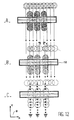
- FIG. 12 shows, on an exemplary embodiment, various possible cases and their mode of treatment when the resolution of the sensor is greater than the diameter of the drops.
- the mark is composed of several lines, three in the commented example, drawn by different drops of a salvo, for example the drops corresponding to the positions 2, 4 and 6 of a burst of nine drops. .
- the difference with respect to the nominal position, will be calculated by the calculator 34, from the calculation of the position of the projection the center of gravity of the mark 51 on an axis X parallel to the advance of the substrate.
- This center of gravity is determined by the sensor elements that see the mark. If, as shown in FIG. 12 part A, the drops are normally positioned, the measurement will be exact. If, as shown in part B, the drops of rank 5 and 6 are displaced relative to their nominal position, the error will be reduced. The same will be true if the random voltage generator 32 is not inhibited at the moment of printing the mark as represented in part C. It goes without saying that it is preferable to inhibit this generator 32 in order to minimize the error.
- the measurement of the position of the marks may result from sampling carried out during the scanning of the print head, the accuracy of the measurement will be increased, and the influence of minimized noise.
Landscapes
- Engineering & Computer Science (AREA)
- Quality & Reliability (AREA)
- Particle Formation And Scattering Control In Inkjet Printers (AREA)
- Ink Jet (AREA)
Claims (7)
- Verfahren zur Veränderung der Ankunftsposition von Tintentropfen, die in regelbarer und sequentieller Weise elektrisch geladen sind, auf einem Substrat (27), wobei die aus einem Druckkopf (25) stammenden Tropfen durch Aufladungselektroden (20) aufgeladen werden, die an einen Spannungsgenerator angeschlossen sind, wobei die Bahnen der Tropfen der Wirkung von Ablenkelektroden (23, 24) ausgesetzt sind, die die Tropfen gemäß dem Wert ihrer elektrischen Ladung zwischen N Positionen ablenken, welche durch ihren Rang j (1 ≤ j ≤ N) definiert sind, nämlich eine erste Position X1, eine letzte Position XN sowie N-2 Zwischenpositionen, wobei die N Positionen ein durch eine Tropfensalve erhaltenes Raster in Form eines geraden Abschnitts definieren, der im Wesentlichen orthogonal zu einer Richtung einer Relativbewegung des Kopfs (25) und des Substrats (27) ist, wobei das Verfahren dadurch gekennzeichnet ist, dass man einem an das Aufladungsmittel jedes zum Substrat hinzulenkenden Tropfens anzulegenden Nominalspannungswert eine zusätzliche algebraische Zufallsspannung überlagert, deren Maximalamplitude ein Bruchteil kleiner als 1 der Differenz zwischen der Nominalspannung, die an die Aufladungselektroden für den Tropfen anzulegen ist, und der Nominalspannung ist, die an die Aufladungselektroden (20) für einen der zwei unmittelbar benachbarten Tropfen des Rasters anzulegen ist.
- Verfahren nach Anspruch 1, dadurch gekennzeichnet, dass der Wert der zusätzlichen Zufallsspannung durch einen pseudozufälligen Erzeugungsalgorithmus erzeugt wird, welcher Algorithmus im Mittel für wenigstens drei Viertel der Werte, die für die Tropfen einer Zahl von Rastern größer als eine vorbestimmte Größe erzeugt werden, einen Wert erzeugt, der kleiner ist als ein Drittel der Differenz zwischen der Nominalspannung, die an die Aufladungselektroden für den Tropfen anzulegen ist, und der Nominalspannung, die an die Aufladungselektroden (20) für einen der zwei unmittelbar benachbarten Tropfen des Rasters anzulegen ist.
- Verfahren nach Anspruch 1, dadurch gekennzeichnet, dass der Wert der zusätzlichen Zufallsspannung durch einen pseudozufälligen Erzeugungsalgorithmus erzeugt wird, welcher Algorithmus im Mittel für wenigstens drei Viertel der Werte, die für die Tropfen einer Zahl von Rastern größer als eine vorbestimmte Größe erzeugt werden, einen Wert erzeugt, der kleiner ist als ein Drittel des Durchschnitts der Differenz zwischen den Nominalspannungen, die an die Aufladungselektroden für zwei unmittelbar benachbarte Tropfen des Rasters anzulegen sind.
- Verfahren nach einem der Ansprüche 1 bis 3 zur Anwendung bei einem Drucker, bei dem das Substrat schrittweise weiterbewegt und in Bändern bedruckt wird, dadurch gekennzeichnet, dass:- man ein laufendes Band sowie eine erste Marke auf das Substrat druckt,- man das Substrat für das Drucken des nächsten Bands weiterbewegt,- man einen algebraischen Abstand zwischen einer theoretischen Nominalposition der Marke und der tatsächlichen Position bestimmt,- man für jeden Tropfen einer Salve eine Substratweiterbewegungskorrektur als eine dynamische Translationskorrekturspannung ϕ des Werts der Aufladungsspannung bestimmt, die an jeden der aus dem Kopf (25) stammenden Tropfen anzulegen ist, um die Ablenkung der Tropfen zu korrigieren und den algebraischen Abstand der Substratposition relativ zu seiner Nominalposition zu kompensieren,- man an jeden der zum Substrat hingelenkten Tropfen der Salve zusätzlich zur Zufallsspannung die berechnete dynamische Substratposition - Translationskorrekturspannung ϕ anlegt
- Verfahren nach Anspruch 4, dadurch gekennzeichnet, dass die zusätzliche Zufallsspannung nicht an die Tropfenaufladungselektroden (20) angelegt wird, während die Marke (51) gedruckt wird.
- Drucker mit kontinuierlichem abgelenkten Strahl, der in Salven Tropfen mit Rang 1 bis N in der Salve ausstößt, wobei die Tropfen einer Salve als Funktion von Daten die ein zu druckendes Motiv definieren, wohl oder nicht auf ein Drucksubstrat (27) gerichtet werden, wobei der Drucker wenigstens aufweist:- einen Druckkopf (25), welcher Kopf Mittel zum Fraktionieren wenigstens eines Tintenstrahls in Tropfen sowie eine zugeordnete Elektrode (20) zum Aufladen der Tropfen umfasst, sowie Mittel (23, 24) zum Ablenken eines Teils der Tropfen zum Drucksubstrat,- Mittel zur Steuerung/Regelung des Drucks, die über eine Einrichtung zum Festhalten der Ladung der zum Substrat hinzulenkenden Tropfen als Funktion ihrer Ränge in der Salve verfügt, gekoppelt mit der Elektrode zur Aufladung der Tropfen,
dadurch gekennzeichnet, dass die Mittel (31) zur Steuerung/Regelung des Drucks einen Generator (32) für eine zusätzliche Zufallsspannung umfassen, der an die Mittel (3') zum Festhalten der Aufladung der Tropfen gekoppelt ist, wobei die Einrichtung (3') zum Festhalten der Aufladung der Tropfen den Wert der Zufallsspannung berücksichtigt, die vom Generator (32) der zusätzlichen Zufallsspannung erzeugt wird, um die Aufladungsspannung jedes Tropfens als Funktion des erzeugten Zufallswerts zu verändern, wodurch die Tropfen jedes Rangs somit um eine Zentralposition herum gestreut werden, die ihrer Position in Abwesenheit der zusätzlichen Spannung entspricht. - Drucker mit kontinuierlichem abgelenkten Strahl nach Anspruch 6, dadurch gekennzeichnet, dass er ferner wenigstens einen Detektor (12) für die Position einer Marke (51) umfasst, welcher Detektor einen Wert liefert, der repäsentativ ist für einen Abstand zwischen einer nominalen Weiterbewegung und einer tatsächlichen Weiterbewegung des Substrats (27), und dass die Mittel (31) zur Steuerung/Regelung des Drucks ferner einen Rechner (35) für die Spannung zur dynamischen Translationskorrektur ϕ der Substratweiterbewegung umfassen, wo-bei dieser Rechner (35) für jeden Tropfen einer Salve als Funktion seines Rangs eine Spannung zur dynamischen Translationskorrektur ϕ der Substratweiterbewegung bestimmt, wobei diese Korrekturspannung einen Substratweiterbewegungsabstandswert berücksichtigt, der von den mit dem Detektor (12) gekoppelten Mitteln (34) geliefert wird, und Abstandswerte bezogen auf eine Nominalposition berechnet, wobei der Rechner (35) für die Spannung zur dynamischen Translationskorrektur ϕ der Substratweiterbewegung mit den Mitteln (3') zum Festhalten der Tropfenladung gekoppelt ist, wobei die Einrichtung zum Festhalten der Tropfenladung den Wert der Spannung zur dynamischen Translationskorrektur ϕ der Substratweiterbewegung berücksichtigt, der vom Rechner (35) für die Spannung zur dynamischen Translationskorrektur ϕ der Substratweiterbewegung erzeugt wird, um die Aufladungsspannung jedes Tropfens als Funktion der Spannung zur dynamischen Translationskorrektur ϕ der Substratweiterbewegung zu verändern.
Applications Claiming Priority (2)
| Application Number | Priority Date | Filing Date | Title |
|---|---|---|---|
| FR9915270A FR2801834B1 (fr) | 1999-12-03 | 1999-12-03 | Procede et imprimante avec masquage de defauts |
| FR9915270 | 1999-12-03 |
Publications (2)
| Publication Number | Publication Date |
|---|---|
| EP1106357A1 EP1106357A1 (de) | 2001-06-13 |
| EP1106357B1 true EP1106357B1 (de) | 2006-01-18 |
Family
ID=9552864
Family Applications (1)
| Application Number | Title | Priority Date | Filing Date |
|---|---|---|---|
| EP00403350A Expired - Lifetime EP1106357B1 (de) | 1999-12-03 | 2000-11-30 | Verfahren und Drucker mit Fehlermaske |
Country Status (8)
| Country | Link |
|---|---|
| US (1) | US6485134B2 (de) |
| EP (1) | EP1106357B1 (de) |
| JP (1) | JP2001162806A (de) |
| CN (1) | CN1137817C (de) |
| DE (1) | DE60025581T2 (de) |
| ES (1) | ES2255960T3 (de) |
| FR (1) | FR2801834B1 (de) |
| IL (1) | IL139886A (de) |
Families Citing this family (12)
| Publication number | Priority date | Publication date | Assignee | Title |
|---|---|---|---|---|
| GB2379412A (en) * | 2001-09-10 | 2003-03-12 | Seiko Epson Corp | Deposition of soluble materials |
| GB0220227D0 (en) * | 2002-08-30 | 2002-10-09 | Xaar Technology Ltd | Droplet deposition apparatus |
| US7252372B2 (en) * | 2004-03-08 | 2007-08-07 | Fujifilm Corporation | Liquid ejection apparatus and ejection control method |
| JP4282520B2 (ja) * | 2004-03-24 | 2009-06-24 | シャープ株式会社 | 信号処理方法、信号出力装置、信号処理装置、画像処理装置、及び画像形成装置 |
| JP4343867B2 (ja) * | 2004-04-13 | 2009-10-14 | キヤノン株式会社 | インクジェット記録装置 |
| US7249829B2 (en) * | 2005-05-17 | 2007-07-31 | Eastman Kodak Company | High speed, high quality liquid pattern deposition apparatus |
| TWI346047B (en) * | 2008-05-12 | 2011-08-01 | Au Optronics Corp | Jetting method for color ink printing |
| FR2934809A1 (fr) * | 2008-08-11 | 2010-02-12 | Imaje Sa | Dispositif d'impression a jet d'encre a injecteur d'air, injecteur d'air et tete d'impression grande largeur associes |
| FR2934810A1 (fr) * | 2008-08-11 | 2010-02-12 | Imaje Sa | Dispositif d'impression a jet d'encre a compensation de vitesse de jet |
| CN102582307B (zh) * | 2011-01-10 | 2014-10-22 | 研能科技股份有限公司 | 快速宽幅打印方法及适用该快速宽幅打印方法的打印装置 |
| JP6217433B2 (ja) * | 2014-02-13 | 2017-10-25 | セイコーエプソン株式会社 | 画像形成装置、及び、ドットパターン決定方法 |
| WO2016169602A1 (en) * | 2015-04-23 | 2016-10-27 | Hewlett-Packard Development Company, L.P. | Printing systems |
Family Cites Families (11)
| Publication number | Priority date | Publication date | Assignee | Title |
|---|---|---|---|---|
| US3786517A (en) | 1972-09-05 | 1974-01-15 | Ibm | Ink jet printer with ink system filter means |
| US4160982A (en) | 1978-03-24 | 1979-07-10 | A. B. Dick Company | Anti-dispersion accumulator for ink jet printing system |
| JPS5664878A (en) * | 1979-11-02 | 1981-06-02 | Ricoh Co Ltd | Ink jet recorder |
| EP0036789A1 (de) * | 1980-03-26 | 1981-09-30 | Cambridge Consultants Limited | Flüssigkeitsstrahldrucker |
| US4321607A (en) * | 1980-06-17 | 1982-03-23 | International Business Machines Corporation | Scaling aerodynamic compensation in an ink jet printer |
| JPS60122162A (ja) | 1983-12-07 | 1985-06-29 | Ricoh Co Ltd | 荷電制御型インクジエツトプリンタ− |
| JPS61114856A (ja) * | 1984-11-09 | 1986-06-02 | Hitachi Ltd | インクジエツト記録装置 |
| US4847631A (en) * | 1986-07-16 | 1989-07-11 | Ricoh Company, Ltd. | Charge and deflection control type ink jet printer |
| US4897667A (en) * | 1987-12-17 | 1990-01-30 | Minolta Camera Kabushiki Kaisha | Ink jet printer |
| JP2673837B2 (ja) * | 1990-11-05 | 1997-11-05 | シルバー精工株式会社 | 連続噴射型インクジェット記録装置 |
| DE69612403T2 (de) * | 1995-08-04 | 2001-07-12 | Domino Printing Sciences Plc, Cambridge | Kontinuierlicher tintenstrahldrucker und betriebsverfahren |
-
1999
- 1999-12-03 FR FR9915270A patent/FR2801834B1/fr not_active Expired - Fee Related
-
2000
- 2000-11-23 IL IL13988600A patent/IL139886A/en not_active IP Right Cessation
- 2000-11-29 JP JP2000362637A patent/JP2001162806A/ja not_active Withdrawn
- 2000-11-30 ES ES00403350T patent/ES2255960T3/es not_active Expired - Lifetime
- 2000-11-30 DE DE60025581T patent/DE60025581T2/de not_active Expired - Lifetime
- 2000-11-30 EP EP00403350A patent/EP1106357B1/de not_active Expired - Lifetime
- 2000-11-30 US US09/726,812 patent/US6485134B2/en not_active Expired - Lifetime
- 2000-12-02 CN CNB001373730A patent/CN1137817C/zh not_active Expired - Fee Related
Also Published As
| Publication number | Publication date |
|---|---|
| EP1106357A1 (de) | 2001-06-13 |
| JP2001162806A (ja) | 2001-06-19 |
| IL139886A0 (en) | 2002-02-10 |
| US6485134B2 (en) | 2002-11-26 |
| ES2255960T3 (es) | 2006-07-16 |
| CN1300672A (zh) | 2001-06-27 |
| US20020018106A1 (en) | 2002-02-14 |
| FR2801834B1 (fr) | 2002-02-01 |
| DE60025581D1 (de) | 2006-04-06 |
| CN1137817C (zh) | 2004-02-11 |
| IL139886A (en) | 2004-05-12 |
| FR2801834A1 (fr) | 2001-06-08 |
| DE60025581T2 (de) | 2006-11-09 |
Similar Documents
| Publication | Publication Date | Title |
|---|---|---|
| EP1106370B1 (de) | Verfahren und Drucker mit Substratverschiebungskontrolle | |
| EP1106371B1 (de) | Drucker mit vereinfachtem Herstellungsverfahren und Herstellungsverfahren | |
| EP0013296B1 (de) | Tintenstrahldrucker mit mehreren Geschwindigkeitsstufen | |
| JP4273126B2 (ja) | 記録装置および補正方法 | |
| US20090002424A1 (en) | Ink jet printing apparatus and method | |
| EP1106357A1 (de) | Verfahren und Drucker mit Fehlermaske | |
| FR2755900A1 (fr) | Presse multicouleur a la continue par jet d'encre, procede de synchronisation d'une telle presse, et produit imprime obtenu a l'aide d'une telle presse | |
| FR2934810A1 (fr) | Dispositif d'impression a jet d'encre a compensation de vitesse de jet | |
| JP2011218565A (ja) | 画像記録装置 | |
| EP0553895B1 (de) | Druckvorrichtung für Abstempel- oder Frankiermaschine oder dergleichen | |
| EP0012887B1 (de) | Vertikales und horizontales Schreiben erlaubender Tintenstrahldrucker | |
| JP2007069428A (ja) | インクジェット記録装置 | |
| EP0997852B1 (de) | Vorrichtung zum Drucken von Postzeichen die lesbarer sind | |
| JP5022977B2 (ja) | 記録装置及び記録制御方法 | |
| EP0702334B1 (de) | System zum Regeln eines Tintenstrahldruckkopfs in einer Frankiermaschine durch Nutzung eines Noniuseffekts | |
| JP2001162912A (ja) | 画像ずれ補正方法および画像形成装置 | |
| EP0702335B1 (de) | System zum Regeln eines Tintenstrahldruckkopfes in einer Frankiermaschine, wobei eine treppenförmige Folge von Motiven gedruckt wird | |
| US20100079525A1 (en) | Reference mark forming device and recording apparatus provided with the reference mark forming device | |
| CH553063A (fr) | Procede d'impression de caracteres alphanumeriques. | |
| JP4900442B2 (ja) | インクジェット記録装置 | |
| JP4492147B2 (ja) | インクジェット記録装置及び記録媒体の移動制御方法 | |
| JP2003320661A (ja) | 印刷装置、印刷方法、プログラム及びコンピュータシステム |
Legal Events
| Date | Code | Title | Description |
|---|---|---|---|
| PUAI | Public reference made under article 153(3) epc to a published international application that has entered the european phase |
Free format text: ORIGINAL CODE: 0009012 |
|
| AK | Designated contracting states |
Kind code of ref document: A1 Designated state(s): BE DE ES FR GB IT |
|
| AX | Request for extension of the european patent |
Free format text: AL;LT;LV;MK;RO;SI |
|
| 17P | Request for examination filed |
Effective date: 20010831 |
|
| AKX | Designation fees paid |
Free format text: BE DE ES FR GB IT |
|
| GRAP | Despatch of communication of intention to grant a patent |
Free format text: ORIGINAL CODE: EPIDOSNIGR1 |
|
| GRAS | Grant fee paid |
Free format text: ORIGINAL CODE: EPIDOSNIGR3 |
|
| GRAA | (expected) grant |
Free format text: ORIGINAL CODE: 0009210 |
|
| AK | Designated contracting states |
Kind code of ref document: B1 Designated state(s): BE DE ES FR GB IT |
|
| PG25 | Lapsed in a contracting state [announced via postgrant information from national office to epo] |
Ref country code: IT Free format text: LAPSE BECAUSE OF FAILURE TO SUBMIT A TRANSLATION OF THE DESCRIPTION OR TO PAY THE FEE WITHIN THE PRESCRIBED TIME-LIMIT;WARNING: LAPSES OF ITALIAN PATENTS WITH EFFECTIVE DATE BEFORE 2007 MAY HAVE OCCURRED AT ANY TIME BEFORE 2007. THE CORRECT EFFECTIVE DATE MAY BE DIFFERENT FROM THE ONE RECORDED. Effective date: 20060118 |
|
| REG | Reference to a national code |
Ref country code: GB Ref legal event code: FG4D Free format text: NOT ENGLISH |
|
| REF | Corresponds to: |
Ref document number: 60025581 Country of ref document: DE Date of ref document: 20060406 Kind code of ref document: P |
|
| GBT | Gb: translation of ep patent filed (gb section 77(6)(a)/1977) |
Effective date: 20060321 |
|
| REG | Reference to a national code |
Ref country code: ES Ref legal event code: FG2A Ref document number: 2255960 Country of ref document: ES Kind code of ref document: T3 |
|
| PLBE | No opposition filed within time limit |
Free format text: ORIGINAL CODE: 0009261 |
|
| STAA | Information on the status of an ep patent application or granted ep patent |
Free format text: STATUS: NO OPPOSITION FILED WITHIN TIME LIMIT |
|
| PG25 | Lapsed in a contracting state [announced via postgrant information from national office to epo] |
Ref country code: BE Free format text: LAPSE BECAUSE OF NON-PAYMENT OF DUE FEES Effective date: 20061130 |
|
| 26N | No opposition filed |
Effective date: 20061019 |
|
| BERE | Be: lapsed |
Owner name: IMAJE S.A. Effective date: 20061130 |
|
| REG | Reference to a national code |
Ref country code: FR Ref legal event code: CD |
|
| PGFP | Annual fee paid to national office [announced via postgrant information from national office to epo] |
Ref country code: DE Payment date: 20101119 Year of fee payment: 11 |
|
| PGFP | Annual fee paid to national office [announced via postgrant information from national office to epo] |
Ref country code: GB Payment date: 20101118 Year of fee payment: 11 Ref country code: IT Payment date: 20101123 Year of fee payment: 11 |
|
| PGFP | Annual fee paid to national office [announced via postgrant information from national office to epo] |
Ref country code: FR Payment date: 20111130 Year of fee payment: 12 Ref country code: ES Payment date: 20111115 Year of fee payment: 12 |
|
| GBPC | Gb: european patent ceased through non-payment of renewal fee |
Effective date: 20121130 |
|
| REG | Reference to a national code |
Ref country code: FR Ref legal event code: ST Effective date: 20130731 |
|
| PG25 | Lapsed in a contracting state [announced via postgrant information from national office to epo] |
Ref country code: IT Free format text: LAPSE BECAUSE OF NON-PAYMENT OF DUE FEES Effective date: 20121130 |
|
| REG | Reference to a national code |
Ref country code: DE Ref legal event code: R119 Ref document number: 60025581 Country of ref document: DE Effective date: 20130601 |
|
| PG25 | Lapsed in a contracting state [announced via postgrant information from national office to epo] |
Ref country code: DE Free format text: LAPSE BECAUSE OF NON-PAYMENT OF DUE FEES Effective date: 20130601 |
|
| PG25 | Lapsed in a contracting state [announced via postgrant information from national office to epo] |
Ref country code: FR Free format text: LAPSE BECAUSE OF NON-PAYMENT OF DUE FEES Effective date: 20121130 Ref country code: GB Free format text: LAPSE BECAUSE OF NON-PAYMENT OF DUE FEES Effective date: 20121130 |
|
| REG | Reference to a national code |
Ref country code: ES Ref legal event code: FD2A Effective date: 20140513 |
|
| PG25 | Lapsed in a contracting state [announced via postgrant information from national office to epo] |
Ref country code: ES Free format text: LAPSE BECAUSE OF NON-PAYMENT OF DUE FEES Effective date: 20121201 |