EP1106414B1 - Vorrichtung zur Befestigung von Anbauteilen an einem Fahrzeug - Google Patents
Vorrichtung zur Befestigung von Anbauteilen an einem Fahrzeug Download PDFInfo
- Publication number
- EP1106414B1 EP1106414B1 EP00124885A EP00124885A EP1106414B1 EP 1106414 B1 EP1106414 B1 EP 1106414B1 EP 00124885 A EP00124885 A EP 00124885A EP 00124885 A EP00124885 A EP 00124885A EP 1106414 B1 EP1106414 B1 EP 1106414B1
- Authority
- EP
- European Patent Office
- Prior art keywords
- exhaust silencer
- interior
- exhaust
- wall
- mounting plate
- Prior art date
- Legal status (The legal status is an assumption and is not a legal conclusion. Google has not performed a legal analysis and makes no representation as to the accuracy of the status listed.)
- Expired - Lifetime
Links
- 230000003584 silencer Effects 0.000 claims abstract description 34
- 238000003466 welding Methods 0.000 claims description 4
- 235000015250 liver sausages Nutrition 0.000 claims 1
- 239000002828 fuel tank Substances 0.000 abstract 1
- 230000005540 biological transmission Effects 0.000 description 2
- 238000002485 combustion reaction Methods 0.000 description 2
- 238000011161 development Methods 0.000 description 2
- 230000018109 developmental process Effects 0.000 description 2
- 238000005452 bending Methods 0.000 description 1
- 230000010354 integration Effects 0.000 description 1
Images

Classifications
-
- B—PERFORMING OPERATIONS; TRANSPORTING
- B60—VEHICLES IN GENERAL
- B60K—ARRANGEMENT OR MOUNTING OF PROPULSION UNITS OR OF TRANSMISSIONS IN VEHICLES; ARRANGEMENT OR MOUNTING OF PLURAL DIVERSE PRIME-MOVERS IN VEHICLES; AUXILIARY DRIVES FOR VEHICLES; INSTRUMENTATION OR DASHBOARDS FOR VEHICLES; ARRANGEMENTS IN CONNECTION WITH COOLING, AIR INTAKE, GAS EXHAUST OR FUEL SUPPLY OF PROPULSION UNITS IN VEHICLES
- B60K15/00—Arrangement in connection with fuel supply of combustion engines or other fuel consuming energy converters, e.g. fuel cells; Mounting or construction of fuel tanks
- B60K15/03—Fuel tanks
- B60K15/063—Arrangement of tanks
- B60K15/067—Mounting of tanks
-
- B—PERFORMING OPERATIONS; TRANSPORTING
- B60—VEHICLES IN GENERAL
- B60K—ARRANGEMENT OR MOUNTING OF PROPULSION UNITS OR OF TRANSMISSIONS IN VEHICLES; ARRANGEMENT OR MOUNTING OF PLURAL DIVERSE PRIME-MOVERS IN VEHICLES; AUXILIARY DRIVES FOR VEHICLES; INSTRUMENTATION OR DASHBOARDS FOR VEHICLES; ARRANGEMENTS IN CONNECTION WITH COOLING, AIR INTAKE, GAS EXHAUST OR FUEL SUPPLY OF PROPULSION UNITS IN VEHICLES
- B60K13/00—Arrangement in connection with combustion air intake or gas exhaust of propulsion units
- B60K13/04—Arrangement in connection with combustion air intake or gas exhaust of propulsion units concerning exhaust
Definitions
- the invention relates to an exhaust silencer including a fastening device, via which it is attached to a frame of a commercial vehicle is, according to the preamble of claim 1.
- EP 0 719 914 A1 describes such an exhaust silencer.
- the fastening device consists of two separately held on the frame, the exhaust silencer body from outside encompassing supports.
- the field of the invention relates to exhaust silencers of commercial vehicles and consequently vehicles of a higher weight class, which have their own Frame.
- Such vehicles usually have large-volume engines with correspondingly large and heavy exhaust mufflers, which corresponding Strength and vibration problems.
- the present invention is based on the object, a Exhaust silencer of the type mentioned in such a way that he with the most compact design possible, stiff and low-vibration on the frame of a Motor vehicle is to be fastened.
- this object is achieved in that the fastening device a mounting plate releasably attached to the frame and at least one protruding from this, on at least one inner wall in the interior of the Exhaust muffler held, no exhaust gas supporting element includes.
- the device according to the invention has the advantage that because of their integration in the exhaust silencer and because of this possible to dispense with external holding elements of the exhaust silencers can be dimensioned larger. In addition, you get an extreme space-saving and compact design. Furthermore, a separate fastening device to be dispensed with for a heat shield, because of The absence of external holding elements can e.g. an insulating mat directly on the Mantle surface of the exhaust silencer can be applied to the heat emission to limit to the outside. Because the fastening device with the Exhaust silencer forms an integral unit and this only by, for example Screwing the mounting plate to the motor vehicle, assembly is extremely simple and inexpensive.
- At least one support element on at least one inner wall in the interior the exhaust silencer increases the structural rigidity of the Exhaust muffler noticeable, in addition, one on the inner wall Uniform power transmission from the support element to the jacket wall of the exhaust silencer guaranteed.
- the support element in particular does not carry the exhaust gas, it can, because none further function obligated by suitable choice of the geometry or the Materials in a wide range depending on the respective requirements be adjusted. For example, if the exhaust silencer is high Has weight or is exposed to large vibrations, the support element be dimensioned accordingly. The support element can consequently be the respective Strength and rigidity requirements are met regardless of others Having to take functions.
- At least one in a horizontal is particularly preferred as the support element Level support tube provided the interior of the exhaust silencer at least partially protruding from at least one holder side Side wall extends to the inner wall.
- a particularly preferred development of the invention provides that the Support tubes in through holes on the cross section of the interior cut, extending transversely to the support tubes, along the Longitudinal extension of the support tubes arranged parallel to each other Inner walls are held with a wall of the exhaust silencer are preferably connected circumferentially by welding or an interference fit.
- the inner walls distributed in the longitudinal direction of the support tubes increase the structural strength of the exhaust silencer, the other becomes one ensures uniform power transmission to the support tubes.
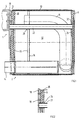
- the one according to the invention is used Device 1 in a preferred embodiment for fastening a hollow attachment in the form of an exhaust muffler 2 on one Side member 4 or side member holder of a commercial vehicle.
- An outer Shell of the exhaust muffler 2 consists essentially of two parallel side walls 6, 8, which by a circumferential Shell wall 10 are interconnected. In one by the Side walls 6, 8 and the jacket wall 10 enclosed interior 12 of the exhaust silencer 2 are of no further interest here Exhaust pipes 14 held.
- the device 1 comprises one on the side member 4 or Side member holder, for example, screwed on, for this purpose with threaded holes 16 or weld nuts provided, preferably outer Mounting plate 18, which is best according to the front view Fig.3 can be seen.
- the mounting plate 18 also has two larger ones Through bores 20, into each of which a support tube 22 is inserted and preferably by a sleeve 24 pushed onto the end Mounting plate 18 is welded (Fig.2).
- the support tubes 22 are in a horizontal plane with a parallel spacing arranged to each other and in the exhaust silencer 2 integrated, preferably at right angles from the mounting plate 18 away, in the closed interior 12 of the exhaust silencer 2 protrude into it.
- the support tubes 22 extend, for example from one side wall 6 of the exhaust silencer 2 to to the opposite side wall 8, with which they e.g. can be connected by welding.
- the mounting plate 18 is from the outside onto the one side wall 6 of the exhaust gas silencer 2 put on and welded to it, for example.
- the mounting plate also contact the side wall 6 from the inside and like the support pipes in the interior 12 of the exhaust muffler be integrated. Then there are only through holes in one To provide side wall 6, which is with the threaded holes 16th cover the mounting plate 18.
- the support tubes 22 are in through holes 26 from on Cross section of the interior 12 of the exhaust gas silencer 2 extending across the support tubes 22, along the longitudinal extent of the support tubes 22 with a parallel distance from one another arranged inner walls 28 preferably by welding held.
- a first inner wall 30 with one side wall 6 in contact from the inside a second inner wall 32 is in the area the other side wall 8 and a third inner wall 34 is in Area arranged between the first and second inner walls 30, 32.
- the inner walls 28 are preferably non-positive or material Connection to the jacket wall 10 by the first and the third inner wall 30, 34 welded to the jacket wall 10 and the second inner wall 32 into the opening enclosed by the jacket wall 10 is pressed.
- the inner walls 28 are continuously flat, with openings provided or formed in the form of transverse and / or longitudinal ribs be that do not take up the entire cross section of the attachment.
- the inner walls 28 guide the weight of the exhaust muffler 2 forth-coming forces and on this due to the Exhaust gas vibrations act dynamic forces via the support pipes 22 into the mounting plate 18, from where it is on the side member 4 of the commercial vehicle can be transmitted.
- the from the mounting plate 18 projecting support tubes 22 are due to the weight mainly stressed on bending and therefore too dimension. Because of the high dynamic alternating loads, those of the exhaust muffler 2 due to the exhaust gas vibrations exposed, there is also sufficient fatigue strength of the individual components and to consider their connections with each other.
Landscapes
- Engineering & Computer Science (AREA)
- Chemical & Material Sciences (AREA)
- Combustion & Propulsion (AREA)
- Transportation (AREA)
- Mechanical Engineering (AREA)
- Life Sciences & Earth Sciences (AREA)
- Sustainable Development (AREA)
- Sustainable Energy (AREA)
- Cooling, Air Intake And Gas Exhaust, And Fuel Tank Arrangements In Propulsion Units (AREA)
- Exhaust Silencers (AREA)
- Automobile Manufacture Line, Endless Track Vehicle, Trailer (AREA)
- Clamps And Clips (AREA)
Description
- Fig. 1
- eine seitliche Querschnittsdarstellung durch einen AbgasSchalldämpfer, welcher mittels einer erfindungsgemäßen Vorrichtung an einem Längsträger eines Nutzfahrzeugs befestigt ist,
- Fig.2
- einen Ausschnitt aus Fig.1,
- Fig.3
- eine Vorderansicht des Schalldämpfers von Fig.1.
Claims (7)
- Abgasschalldämpfer beinhaltend eine Befestigungsvorrichtung (1), über welche er an einem Rahmen (4) eines Nutzfahrzeugs befestigt ist, dadurch gekennzeichnet, dass die Befestigungsvorrichtung (1) eine am Rahmen (4) lösbar befestigte Montageplatte (18) und mindestens ein von dieser weg ragendes, an einer Innenwand (28) im Innenraum (12) des Abgasschalldämpfers (2) gehaltenes, kein Abgas führendes Stützelement (22) umfasst.
- Abgasschalldämpfer nach Anspruch 1, dadurch gekennzeichnet, dass als Stützelement wenigstens ein in einer horizontalen Ebene angeordnetes Stützrohr (22) vorgesehen ist, das den Innenraum (12) des Abgasschalldämpfers (2) wenigstens teilweise durchragend sich mindestens von einer halterseitigen Seitenwand (6) bis zur Innenwand (28) erstreckt.
- Abgasschalldämpfer nach Anspruch 2, dadurch gekennzeichnet, dass die Montageplatte (18) von außen oder von innen an der halterseitigen Seitenwand (6) vorzugsweise durch Schweißung befestigt ist.
- Abgasschalldämpfer nach Anspruch 3, dadurch gekennzeichnet, dass die Montageplatte (18) mit Gewindebohrungen (16) oder Schweißmuttern versehen ist, um sie mittels Schrauben am Rahmen (4) des Nutzfahrzeugs lösbar zu befestigen.
- Abgasschalldämpfer nach Anspruch 4, dadurch gekennzeichnet, dass die Stützrohre (22) endseitig durch Muffen (24) an die Montageplatte (18) angeschweißt sind.
- Abgasschalldämpfer nach Anspruch 5, dadurch gekennzeichnet, daß die Stützrohre (22) in kraftübertragender Verbindung mit mehreren Innenwänden (28) stehen.
- Abgasschalldämpfer nach Anspruch 6, dadurch gekennzeichnet, dass die Stützrohre (22) in Durchgangsbohrungen (26) von auf den Querschnitt des Innenraums (12) zugeschnittenen, sich quer zu den Stützrohren (22) erstreckenden, entlang der Längserstreckung der Stützrohre (22) mit Parallelabstand zueinander angeordneten Innenwänden (28) gehalten sind, die mit einer Wandung (10) des Abgasschalldämpfers (2) vorzugsweise durch Schweißung oder Preßsitz umlaufend verbunden sind.
Applications Claiming Priority (2)
| Application Number | Priority Date | Filing Date | Title |
|---|---|---|---|
| DE19959350 | 1999-12-09 | ||
| DE19959350A DE19959350A1 (de) | 1999-12-09 | 1999-12-09 | Vorrichtung zur Befestigung von Anbauteilen an einem Fahrzeug |
Publications (3)
| Publication Number | Publication Date |
|---|---|
| EP1106414A2 EP1106414A2 (de) | 2001-06-13 |
| EP1106414A3 EP1106414A3 (de) | 2003-08-13 |
| EP1106414B1 true EP1106414B1 (de) | 2004-08-11 |
Family
ID=7931986
Family Applications (1)
| Application Number | Title | Priority Date | Filing Date |
|---|---|---|---|
| EP00124885A Expired - Lifetime EP1106414B1 (de) | 1999-12-09 | 2000-11-15 | Vorrichtung zur Befestigung von Anbauteilen an einem Fahrzeug |
Country Status (3)
| Country | Link |
|---|---|
| EP (1) | EP1106414B1 (de) |
| AT (1) | ATE273148T1 (de) |
| DE (2) | DE19959350A1 (de) |
Families Citing this family (2)
| Publication number | Priority date | Publication date | Assignee | Title |
|---|---|---|---|---|
| DE10239259B3 (de) * | 2002-08-22 | 2004-02-19 | Roth-Technik Austria Ges.M.B.H. | Verbidung eines dünnwandigen Körpers mit einem demgegenüber dickerwandigen Körper |
| SE526343C2 (sv) * | 2004-09-20 | 2005-08-23 | Volvo Lastvagnar Ab | Anordning vid ljuddämpare |
Family Cites Families (10)
| Publication number | Priority date | Publication date | Assignee | Title |
|---|---|---|---|---|
| JPS6216368Y2 (de) * | 1980-12-18 | 1987-04-24 | ||
| US4854417A (en) * | 1987-08-03 | 1989-08-08 | Honda Giken Kogyo Kabushiki Kaisha | Exhaust muffler for an internal combustion engine |
| DE3916542A1 (de) | 1989-05-20 | 1990-11-22 | Audi Ag | Vorrichtung zum befestigen eines bauteiles an einer wand |
| DE9014978U1 (de) * | 1990-10-30 | 1992-03-12 | Roth-Technik GmbH, 76571 Gaggenau | Befestigungselement für einen Schalldämpfer einer Abgasanlage |
| SE506516C2 (sv) * | 1994-12-30 | 1997-12-22 | Scania Cv Ab | Avgasljuddämpare för motorfodon |
| DE19605702C2 (de) * | 1996-02-16 | 2000-02-03 | Man Nutzfahrzeuge Ag | Kraftstoffbehältersystem für Lastkraftwagen oder Omnibusse |
| DE19605703C2 (de) * | 1996-02-16 | 2000-02-03 | Man Nutzfahrzeuge Ag | Behältersystem für Betriebsmittel von Lastkraftwagen und Omnibussen |
| DE19747417A1 (de) * | 1997-10-27 | 1999-04-29 | Ewald Witte Gmbh & Co Kg | Befestigungsvorrichtung zum Anbringen an Fahrzeugen, insbesondere Kraftfahrzeugen |
| JP3930961B2 (ja) * | 1998-01-27 | 2007-06-13 | 株式会社共立 | 内燃エンジンのマフラー |
| DE19809229A1 (de) * | 1998-03-04 | 1999-09-09 | Delphi Automotive Systems Gmbh | Verfahren zum Befestigen eines Anbauteiles |
-
1999
- 1999-12-09 DE DE19959350A patent/DE19959350A1/de not_active Withdrawn
-
2000
- 2000-11-15 EP EP00124885A patent/EP1106414B1/de not_active Expired - Lifetime
- 2000-11-15 AT AT00124885T patent/ATE273148T1/de active
- 2000-11-15 DE DE50007368T patent/DE50007368D1/de not_active Expired - Lifetime
Also Published As
| Publication number | Publication date |
|---|---|
| EP1106414A3 (de) | 2003-08-13 |
| DE19959350A1 (de) | 2001-06-13 |
| ATE273148T1 (de) | 2004-08-15 |
| DE50007368D1 (de) | 2004-09-16 |
| EP1106414A2 (de) | 2001-06-13 |
Similar Documents
| Publication | Publication Date | Title |
|---|---|---|
| DE69927763T2 (de) | Maschinenblock | |
| EP3181390B1 (de) | Fahrzeug mit einem antriebsaggregat und einer aggregatelagerung | |
| DE102007044636B4 (de) | Fahrzeug mit einer Brennstoffzelleneinheit | |
| EP2165875A2 (de) | Befestigungseinrichtung, insbesondere bei Kraftfahrzeugen | |
| DE19920051A1 (de) | Fahrschemel für eine Vorderachse eines Kraftfahrzeugs | |
| DE102010004493B4 (de) | Ölwanne für einen Verbrennungsmotor | |
| DE10039657C2 (de) | Vorrichtung zum Befestigen eines Motors eines Kraftfahrzeuges | |
| EP3158842A1 (de) | Landwirtschaftliches fahrzeug | |
| DE10216272B4 (de) | Abgasbehandlungsanordnung für eine Brennkraftmaschine | |
| DE4207193C2 (de) | Lagerung eines Antriebsaggregates | |
| DE3914611C2 (de) | Verdampfungsbrenner für ein mit flüssigem Brennstoff betriebenes Heizgerät | |
| EP4122736A1 (de) | Fahrzeugachse und fahrzeug | |
| DE102009053112B4 (de) | Motor mit Ölpumpendämpfer, gedämpfte Ölpumpenanordnung sowie Ölpumpendämpfer | |
| EP3539808B1 (de) | Anordnung zur antriebslagerung | |
| DE4209526C2 (de) | Kraftfahrzeug-Kraftübertragungsanordnung | |
| DE10257562A1 (de) | Massenausgleich für einen Verbrennungsmotor | |
| DE10035129B4 (de) | Motorrad-Auspufftopf | |
| DE19738830A1 (de) | Karosserieabschnitt mit einem Cockpitquerträger | |
| EP1106414A2 (de) | Vorrichtung zur Befestigung von Anbauteilen an einem Fahrzeug | |
| WO2007009725A1 (de) | Hilfstragrahmen zur aufnahme von achsen eines fahrzeugs | |
| DE3342820C2 (de) | ||
| EP2336540B1 (de) | Kraftwagen mit einem Luftfiltergehäuse | |
| DE69526567T2 (de) | Abgassystem für Kraftfahrzeuge und ein Schalldämpfer, der Bestandteil des Abgassystems ist | |
| DE2736378C2 (de) | Hilfsmaschinen für die luftgekühlte Brennkraftmaschine eines Schleppers | |
| DE102021119975A1 (de) | Nutzfahrzeug-automatikgetriebe-antriebsstranghalterung |
Legal Events
| Date | Code | Title | Description |
|---|---|---|---|
| PUAI | Public reference made under article 153(3) epc to a published international application that has entered the european phase |
Free format text: ORIGINAL CODE: 0009012 |
|
| 17P | Request for examination filed |
Effective date: 20001115 |
|
| AK | Designated contracting states |
Kind code of ref document: A2 Designated state(s): AT BE CH CY DE DK ES FI FR GB GR IE IT LI LU MC NL PT SE TR |
|
| AX | Request for extension of the european patent |
Free format text: AL;LT;LV;MK;RO;SI |
|
| PUAL | Search report despatched |
Free format text: ORIGINAL CODE: 0009013 |
|
| AK | Designated contracting states |
Designated state(s): AT BE CH CY DE DK ES FI FR GB GR IE IT LI LU MC NL PT SE TR |
|
| AX | Request for extension of the european patent |
Extension state: AL LT LV MK RO SI |
|
| 17Q | First examination report despatched |
Effective date: 20031211 |
|
| GRAP | Despatch of communication of intention to grant a patent |
Free format text: ORIGINAL CODE: EPIDOSNIGR1 |
|
| GRAS | Grant fee paid |
Free format text: ORIGINAL CODE: EPIDOSNIGR3 |
|
| AKX | Designation fees paid |
Designated state(s): AT DE FR IT NL SE |
|
| GRAA | (expected) grant |
Free format text: ORIGINAL CODE: 0009210 |
|
| RBV | Designated contracting states (corrected) |
Designated state(s): AT DE FR IT NL |
|
| AK | Designated contracting states |
Kind code of ref document: B1 Designated state(s): AT DE FR IT NL SE |
|
| RBV | Designated contracting states (corrected) |
Designated state(s): AT DE FR IT NL SE |
|
| REG | Reference to a national code |
Ref country code: IE Ref legal event code: FG4D Free format text: GERMAN |
|
| REF | Corresponds to: |
Ref document number: 50007368 Country of ref document: DE Date of ref document: 20040916 Kind code of ref document: P |
|
| REG | Reference to a national code |
Ref country code: SE Ref legal event code: TRGR |
|
| REG | Reference to a national code |
Ref country code: IE Ref legal event code: FD4D |
|
| ET | Fr: translation filed | ||
| PLBE | No opposition filed within time limit |
Free format text: ORIGINAL CODE: 0009261 |
|
| STAA | Information on the status of an ep patent application or granted ep patent |
Free format text: STATUS: NO OPPOSITION FILED WITHIN TIME LIMIT |
|
| 26N | No opposition filed |
Effective date: 20050512 |
|
| REG | Reference to a national code |
Ref country code: FR Ref legal event code: PLFP Year of fee payment: 16 |
|
| REG | Reference to a national code |
Ref country code: FR Ref legal event code: PLFP Year of fee payment: 17 |
|
| REG | Reference to a national code |
Ref country code: FR Ref legal event code: PLFP Year of fee payment: 18 |
|
| PGFP | Annual fee paid to national office [announced via postgrant information from national office to epo] |
Ref country code: SE Payment date: 20191125 Year of fee payment: 20 Ref country code: DE Payment date: 20191016 Year of fee payment: 20 Ref country code: NL Payment date: 20191121 Year of fee payment: 20 |
|
| PGFP | Annual fee paid to national office [announced via postgrant information from national office to epo] |
Ref country code: FR Payment date: 20191121 Year of fee payment: 20 Ref country code: IT Payment date: 20191120 Year of fee payment: 20 |
|
| PGFP | Annual fee paid to national office [announced via postgrant information from national office to epo] |
Ref country code: AT Payment date: 20191119 Year of fee payment: 20 |
|
| REG | Reference to a national code |
Ref country code: DE Ref legal event code: R071 Ref document number: 50007368 Country of ref document: DE |
|
| REG | Reference to a national code |
Ref country code: NL Ref legal event code: MK Effective date: 20201114 |
|
| REG | Reference to a national code |
Ref country code: AT Ref legal event code: MK07 Ref document number: 273148 Country of ref document: AT Kind code of ref document: T Effective date: 20201115 |