EP1106432B1 - Beleuchungsvorrichtung mit gegebener Beleuchtungsrichtung - Google Patents
Beleuchungsvorrichtung mit gegebener Beleuchtungsrichtung Download PDFInfo
- Publication number
- EP1106432B1 EP1106432B1 EP99124455A EP99124455A EP1106432B1 EP 1106432 B1 EP1106432 B1 EP 1106432B1 EP 99124455 A EP99124455 A EP 99124455A EP 99124455 A EP99124455 A EP 99124455A EP 1106432 B1 EP1106432 B1 EP 1106432B1
- Authority
- EP
- European Patent Office
- Prior art keywords
- lighting device
- light
- light beam
- vertical
- downward
- Prior art date
- Legal status (The legal status is an assumption and is not a legal conclusion. Google has not performed a legal analysis and makes no representation as to the accuracy of the status listed.)
- Expired - Lifetime
Links
Images



Classifications
-
- F—MECHANICAL ENGINEERING; LIGHTING; HEATING; WEAPONS; BLASTING
- F21—LIGHTING
- F21V—FUNCTIONAL FEATURES OR DETAILS OF LIGHTING DEVICES OR SYSTEMS THEREOF; STRUCTURAL COMBINATIONS OF LIGHTING DEVICES WITH OTHER ARTICLES, NOT OTHERWISE PROVIDED FOR
- F21V23/00—Arrangement of electric circuit elements in or on lighting devices
- F21V23/04—Arrangement of electric circuit elements in or on lighting devices the elements being switches
- F21V23/0442—Arrangement of electric circuit elements in or on lighting devices the elements being switches activated by means of a sensor, e.g. motion or photodetectors
- F21V23/0492—Arrangement of electric circuit elements in or on lighting devices the elements being switches activated by means of a sensor, e.g. motion or photodetectors the sensor detecting a change in orientation, a movement or an acceleration of the lighting device, e.g. a tilt switch
-
- B—PERFORMING OPERATIONS; TRANSPORTING
- B60—VEHICLES IN GENERAL
- B60Q—ARRANGEMENT OF SIGNALLING OR LIGHTING DEVICES, THE MOUNTING OR SUPPORTING THEREOF OR CIRCUITS THEREFOR, FOR VEHICLES IN GENERAL
- B60Q1/00—Arrangement of optical signalling or lighting devices, the mounting or supporting thereof or circuits therefor
- B60Q1/02—Arrangement of optical signalling or lighting devices, the mounting or supporting thereof or circuits therefor the devices being primarily intended to illuminate the way ahead or to illuminate other areas of way or environments
- B60Q1/04—Arrangement of optical signalling or lighting devices, the mounting or supporting thereof or circuits therefor the devices being primarily intended to illuminate the way ahead or to illuminate other areas of way or environments the devices being headlights
- B60Q1/06—Arrangement of optical signalling or lighting devices, the mounting or supporting thereof or circuits therefor the devices being primarily intended to illuminate the way ahead or to illuminate other areas of way or environments the devices being headlights adjustable, e.g. remotely-controlled from inside vehicle
- B60Q1/08—Arrangement of optical signalling or lighting devices, the mounting or supporting thereof or circuits therefor the devices being primarily intended to illuminate the way ahead or to illuminate other areas of way or environments the devices being headlights adjustable, e.g. remotely-controlled from inside vehicle automatically
-
- B—PERFORMING OPERATIONS; TRANSPORTING
- B60—VEHICLES IN GENERAL
- B60Q—ARRANGEMENT OF SIGNALLING OR LIGHTING DEVICES, THE MOUNTING OR SUPPORTING THEREOF OR CIRCUITS THEREFOR, FOR VEHICLES IN GENERAL
- B60Q1/00—Arrangement of optical signalling or lighting devices, the mounting or supporting thereof or circuits therefor
- B60Q1/02—Arrangement of optical signalling or lighting devices, the mounting or supporting thereof or circuits therefor the devices being primarily intended to illuminate the way ahead or to illuminate other areas of way or environments
- B60Q1/04—Arrangement of optical signalling or lighting devices, the mounting or supporting thereof or circuits therefor the devices being primarily intended to illuminate the way ahead or to illuminate other areas of way or environments the devices being headlights
- B60Q1/06—Arrangement of optical signalling or lighting devices, the mounting or supporting thereof or circuits therefor the devices being primarily intended to illuminate the way ahead or to illuminate other areas of way or environments the devices being headlights adjustable, e.g. remotely-controlled from inside vehicle
- B60Q1/08—Arrangement of optical signalling or lighting devices, the mounting or supporting thereof or circuits therefor the devices being primarily intended to illuminate the way ahead or to illuminate other areas of way or environments the devices being headlights adjustable, e.g. remotely-controlled from inside vehicle automatically
- B60Q1/10—Arrangement of optical signalling or lighting devices, the mounting or supporting thereof or circuits therefor the devices being primarily intended to illuminate the way ahead or to illuminate other areas of way or environments the devices being headlights adjustable, e.g. remotely-controlled from inside vehicle automatically due to vehicle inclination, e.g. due to load distribution
- B60Q1/115—Arrangement of optical signalling or lighting devices, the mounting or supporting thereof or circuits therefor the devices being primarily intended to illuminate the way ahead or to illuminate other areas of way or environments the devices being headlights adjustable, e.g. remotely-controlled from inside vehicle automatically due to vehicle inclination, e.g. due to load distribution by electric means
-
- B—PERFORMING OPERATIONS; TRANSPORTING
- B60—VEHICLES IN GENERAL
- B60Q—ARRANGEMENT OF SIGNALLING OR LIGHTING DEVICES, THE MOUNTING OR SUPPORTING THEREOF OR CIRCUITS THEREFOR, FOR VEHICLES IN GENERAL
- B60Q1/00—Arrangement of optical signalling or lighting devices, the mounting or supporting thereof or circuits therefor
- B60Q1/02—Arrangement of optical signalling or lighting devices, the mounting or supporting thereof or circuits therefor the devices being primarily intended to illuminate the way ahead or to illuminate other areas of way or environments
- B60Q1/04—Arrangement of optical signalling or lighting devices, the mounting or supporting thereof or circuits therefor the devices being primarily intended to illuminate the way ahead or to illuminate other areas of way or environments the devices being headlights
- B60Q1/18—Arrangement of optical signalling or lighting devices, the mounting or supporting thereof or circuits therefor the devices being primarily intended to illuminate the way ahead or to illuminate other areas of way or environments the devices being headlights being additional front lights
-
- B—PERFORMING OPERATIONS; TRANSPORTING
- B63—SHIPS OR OTHER WATERBORNE VESSELS; RELATED EQUIPMENT
- B63B—SHIPS OR OTHER WATERBORNE VESSELS; EQUIPMENT FOR SHIPPING
- B63B22/00—Buoys
- B63B22/16—Buoys specially adapted for marking a navigational route
- B63B22/166—Buoys specially adapted for marking a navigational route comprising a light
-
- B—PERFORMING OPERATIONS; TRANSPORTING
- B63—SHIPS OR OTHER WATERBORNE VESSELS; RELATED EQUIPMENT
- B63B—SHIPS OR OTHER WATERBORNE VESSELS; EQUIPMENT FOR SHIPPING
- B63B45/00—Arrangements or adaptations of signalling or lighting devices
- B63B45/04—Arrangements or adaptations of signalling or lighting devices the devices being intended to indicate the vessel or parts thereof
-
- F—MECHANICAL ENGINEERING; LIGHTING; HEATING; WEAPONS; BLASTING
- F21—LIGHTING
- F21S—NON-PORTABLE LIGHTING DEVICES; SYSTEMS THEREOF; VEHICLE LIGHTING DEVICES SPECIALLY ADAPTED FOR VEHICLE EXTERIORS
- F21S41/00—Illuminating devices specially adapted for vehicle exteriors, e.g. headlamps
- F21S41/10—Illuminating devices specially adapted for vehicle exteriors, e.g. headlamps characterised by the light source
- F21S41/19—Attachment of light sources or lamp holders
- F21S41/192—Details of lamp holders, terminals or connectors
-
- F—MECHANICAL ENGINEERING; LIGHTING; HEATING; WEAPONS; BLASTING
- F21—LIGHTING
- F21S—NON-PORTABLE LIGHTING DEVICES; SYSTEMS THEREOF; VEHICLE LIGHTING DEVICES SPECIALLY ADAPTED FOR VEHICLE EXTERIORS
- F21S41/00—Illuminating devices specially adapted for vehicle exteriors, e.g. headlamps
- F21S41/20—Illuminating devices specially adapted for vehicle exteriors, e.g. headlamps characterised by refractors, transparent cover plates, light guides or filters
- F21S41/28—Cover glass
-
- F—MECHANICAL ENGINEERING; LIGHTING; HEATING; WEAPONS; BLASTING
- F21—LIGHTING
- F21S—NON-PORTABLE LIGHTING DEVICES; SYSTEMS THEREOF; VEHICLE LIGHTING DEVICES SPECIALLY ADAPTED FOR VEHICLE EXTERIORS
- F21S41/00—Illuminating devices specially adapted for vehicle exteriors, e.g. headlamps
- F21S41/60—Illuminating devices specially adapted for vehicle exteriors, e.g. headlamps characterised by a variable light distribution
- F21S41/65—Illuminating devices specially adapted for vehicle exteriors, e.g. headlamps characterised by a variable light distribution by acting on light sources
- F21S41/663—Illuminating devices specially adapted for vehicle exteriors, e.g. headlamps characterised by a variable light distribution by acting on light sources by switching light sources
-
- B—PERFORMING OPERATIONS; TRANSPORTING
- B60—VEHICLES IN GENERAL
- B60Q—ARRANGEMENT OF SIGNALLING OR LIGHTING DEVICES, THE MOUNTING OR SUPPORTING THEREOF OR CIRCUITS THEREFOR, FOR VEHICLES IN GENERAL
- B60Q2300/00—Indexing codes for automatically adjustable headlamps or automatically dimmable headlamps
- B60Q2300/05—Special features for controlling or switching of the light beam
- B60Q2300/054—Variable non-standard intensity, i.e. emission of various beam intensities different from standard intensities, e.g. continuous or stepped transitions of intensity
-
- F—MECHANICAL ENGINEERING; LIGHTING; HEATING; WEAPONS; BLASTING
- F21—LIGHTING
- F21W—INDEXING SCHEME ASSOCIATED WITH SUBCLASSES F21K, F21L, F21S and F21V, RELATING TO USES OR APPLICATIONS OF LIGHTING DEVICES OR SYSTEMS
- F21W2107/00—Use or application of lighting devices on or in particular types of vehicles
- F21W2107/10—Use or application of lighting devices on or in particular types of vehicles for land vehicles
-
- F—MECHANICAL ENGINEERING; LIGHTING; HEATING; WEAPONS; BLASTING
- F21—LIGHTING
- F21Y—INDEXING SCHEME ASSOCIATED WITH SUBCLASSES F21K, F21L, F21S and F21V, RELATING TO THE FORM OR THE KIND OF THE LIGHT SOURCES OR OF THE COLOUR OF THE LIGHT EMITTED
- F21Y2115/00—Light-generating elements of semiconductor light sources
- F21Y2115/10—Light-emitting diodes [LED]
-
- Y—GENERAL TAGGING OF NEW TECHNOLOGICAL DEVELOPMENTS; GENERAL TAGGING OF CROSS-SECTIONAL TECHNOLOGIES SPANNING OVER SEVERAL SECTIONS OF THE IPC; TECHNICAL SUBJECTS COVERED BY FORMER USPC CROSS-REFERENCE ART COLLECTIONS [XRACs] AND DIGESTS
- Y10—TECHNICAL SUBJECTS COVERED BY FORMER USPC
- Y10S—TECHNICAL SUBJECTS COVERED BY FORMER USPC CROSS-REFERENCE ART COLLECTIONS [XRACs] AND DIGESTS
- Y10S362/00—Illumination
- Y10S362/802—Position or condition responsive switch
Definitions
- a typical use would be a navigation light on a ship. These red or green lights are required on ships so that other ships will know of their location and avoid potential accidents.
- Navigation lights are normally constructed to provide a light beam of a specification intensity and a specification vertical beamwidth above and below the horizontal plane. Unfortunately, ships and other craft such as sailboats roll in the water beyond the vertical specification beamwidth of the lights such that the navigation lights misdirect their projected beam either upward or downward. This misdirection of light can create a substantial hazard as other ships are denied the lighting signal that can alert them to a potential accident.
- the lighting device may be flashing.
- a flashing requirement intensifies the problem of misdirected light because for the light to be visible to a horizontal observer during a rolling motion the light must flash at substantially the exact time that the light is projecting light in the horizontal direction. Normally this requires the lighting device to be disposed substantially in the vertical position. If the light flashes when the projected beam is misdirected above or below the horizontal virtually all of the light energy will miss the observer. If the light continues to flash at the time its beam is directed away from the horizontal, it can remain unseen for an unacceptable length of time.
- a misdirected steady light also has its visibility decreased by a rolling movement of the lighting device however, as the lighting device oscillates about the vertical it will at least for a short period of time direct some of its light in the direction of a horizontal observer.
- An electrical lighting device according to the preamble of claim 1 is known from FR-A-2 345 900 . Departing from this prior art, the problem underlying the present invention is to provide a lighting device which throughout angular movement about a vertical reference plane maximizes the percentage of light it emits that is concentrated within a vertical angular beamspread about a selected direction.
- the present invention will find application whenever a lighting device is required to project a beam of light in a selected direction relative to a vertical even though the lighting device cannot be disposed at a fixed angular position relative to the second beam of light that includes within that beam light parallel to the selected direction.
- the present invention will find application whenever a lighting device is required to project a beam of light in a selected direction relative to a vertical even though the lighting device cannot be disposed at a fixed angular position relative to the vertical.
- Uses for the present invention include a navigation light on a ship where the lighting device rolls relative to the vertical but its projected light beam is required to be directed along the horizontal.
- the present invention can also be employed as a buoy light which oscillates in the water but is required to project a substantially horizontal beam.
- Another use can be found as a headlight for a vehicle whereby the projected beam from the lighting device should remain directed in a selected direction angularly below the horizontal even as the vehicle and light mounted thereon rotate relative to the vertical due to bumps or rocks on the road.
- the present invention emits a light beam which directs light in a selected direction relative to a vertical line or vertical plane. It further maintains a projected light beam in the selected direction even when the lighting device is angularly displaced or rotated about the vertical plane. It achieves this objective by providing a plurality beam means to project a plurality of oblique light beams. If the selected direction is along a horizontal plane and the lighting device is in its vertical position each of the projected light beams is directed either along the horizontal plane, diverging upward about the horizontal plane or diverging downward about the horizontal plane.
- Each of the potentially projected light beams includes a vertical beamwidth to cooperate with the beamwidths of the other projected light beams to form a composite light beam having a vertical beamspread approximately equal to the range of angular movement the lighting device is expected to experience.
- the lighting device should also provide the minimum intensity required for the intended use.
- One method of achieving this objective is for the composite beam to provide the minimum intensity throughout is vertical beamspread.
- a power control means which selectively illuminates one or more of the beam means at the time that at least a portion of the projected light from that selected beam means is projected parallel to the horizontal is also included.
- the power control means can illuminate the selected beam means when the lighting device attains an established angular orientation relative to a vertical line or plane.
- the selected beam means can illuminate the selected beam means when the axis of that beam means attains an established angular orientation relative to the selected direction.
- it can illuminate a selected beam means when some other reference such as the axis of any beam attains an established angular orientation relative to the selected direction.
- a beam means is simply a lighting device which projects a concentrated light beam.
- the present invention requires a plurality of component lighting devices or beam means.
- the individual component lighting device employed in the current invention can be assembled from readily available components. They are also available as complete assemblies such as sealed beam bulbs.
- a beam means can be formed from a large variety of combinations of a light source and an optic. Since most light sources including LED elements emit light which comprises a widely diverging spatial radiation pattern the emitted light is normally concentrated by an optical system such as a reflector, encapsulating refractor or separate lens.
- the reflector is commercially known as a successful light collection device and in its most common form will collect the light into a concentrated beam pattern.
- the encapsulating refractor also commercially known is usually a transparent epoxy cast around the LED element into a curved aspheric shape to form a LED lamp. The curved aspheric shape refracts the light from the LED element as it passes through the refractor to concentrate the light into a concentrated round beam pattern. This design is found in the commercially available T 1 3/4 LED lamp.
- the separate light condensing piano convex lens is currently commercially employed to function with a LED lamp to collect the light into a concentrated projected light beam.
- the beam means can also include an electroluminescent source and a curved condensing lens.
- the current invention requires at least two beam means. For some uses to be hereinafter described a larger number of beam means will represent an improved design.
- Projected light beams are defined in a number of ways.
- a common system which is employed in this disclosure defines a central axis which indicates the direction of maximum intensity.
- Directions within a vertical reference plane drawn coincident with the central axis representing directions indicating intensities of a percentage of the maximum intensity (usually fifty but any percentage can be employed) define the vertical boundaries of the vertical beamspread.
- Directions within a horizontal plane drawn coincident with the central axis representing directions indicating intensities of a percentage of the maximum intensity (usually fifty but any percentage can be employed) define the horizontal boundaries of the horizontal beamspread.
- the included angle between the vertical beamspread boundaries is the vertical angular beamspread.
- the included angle between the horizontal beamspread boundaries is the horizontal angular beamspread.
- the central axis of a projected light beam is a bisector of the vertical angular beamspread. It is also usually a bisector of the horizontal angular beamspread.
- the location of the central axis of the projected beams is helpful in describing some embodiments of the current invention but the invention can be constructed using almost any projected light beams regardless of their intensity profiles.
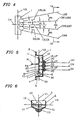
- Figures 1, 2, 3 , and 4 are perspective, front, plan and side views respectively of lighting device 50 which represents a preferred embodiment of the current invention used as a navigation light on a ship.
- Figure 3 is a plan view of lighting device 50 with vertical reference plane V1 and perpendicular vertical reference tilt plane V2 both coincident with switch axis SA to be later described.
- FIG. 5 is a partial cross-sectional view of lighting device 50 taken across line 5-5' of figure 2 .
- Figure 6 is a partial cross-sectional view of lighting device 50 taken across line 6-6' of figure 2 .
- Lighting device 50 comprises housing 1 usually injection molded of a transparent plastic such as polycarbonate. Housing 1 which is the only component shown cross-sectioned includes top flange 2 with top mount hole 3 and bottom flange 4 with bottom mount hole 5. Top flange 2 and bottom flange 4 permit lighting device 50 to be bolted to a vertical surface such as a bulkhead on a ship thereby establishing a vertical position. Housing 1 further is molded into a shape which includes an upward optic UO, central optic CO, downward optic DO and surrounding wall 6 forming cavity 7. Cavity 7 accepts circuit assembly 10 which is fastened to housing 1 by threading upper screw 11 into upper housing rib 12 and lower screw 13 into lower housing rib 14.
- circuit assembly 10 comprises upward LED lamp UL, central LED lamp CL, downward LED lamp DL, mercury tilt switch 20 and NOR gate 15 all mounted on circuit board 16.
- Positive power line P1 and negative power line P2 bring a power supply voltage VCC to circuit assembly 10.
- lighting device 50 can alternatively be energized by a battery potentially stored within cavity 7 of housing 1.
- Circuit board 16 has upper hole 17 and lower hole 18 provided to accept upper screw 11 and lower screw 13 respectively to facilitate fastening circuit assembly 10 to housing 1.
- Either circuit board 16 or housing 1 can be considered as a full or partial support means for power control means 8 and circuit assembly 10.
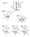
- FIGS 8 and 9 are perspective and plan views respectively of a standard commercially available two direction mercury tilt switch 20.
- Tilt switch 20 comprises a metal body 19, common electrical terminal TC, downward terminal T1 and upward terminal T2.
- Switch axis SA passes through geometric center 9 of metal body 19.
- Upward beam means UM includes upward LED lamp UL positioned approximately at upward focal point UF of upward optic UO such that when energized they cooperate to emit upward beam UB.
- Upward horizontal reference plane UH is a horizontal reference plane coincident with upward focal point UF. This reference plane as well as all other horizontal reference planes maintain their horizontal disposition regardless of the angular tilt of lighting device 50.
- Upward beam UB comprises upward beam axis UA which represents the direction of maximum intensity within upward beam UB, upward boundary top UBT and upward boundary bottom UBB represent directions indicating intensities at fifty percent of the maximum intensity.
- Central beam means CM includes central LED lamp CL positioned near central focal point CF of central optic CO positioned such that when energized they cooperate to emit central beam CB.
- Central horizontal reference plane CH is a horizontal reference plane coincident with central focal point CF.
- Central beam CB comprises central beam axis CA which is a direction of maximum intensity within central beam CB.
- Downward beam means DM includes downward LED lamp DL positioned near downward focal point DF of downward optic DO such that when energized they cooperate to emit downward beam DB.
- Downward horizontal reference plane DH is a horizontal reference plane coincident with downward focal point DF.
- Downward beam DM comprises downward axis DA which is a direction of maximum intensity within downward beam DB.
- Lighting device 50 therefore comprises three beam means which are substantially identical with identical components and beam profiles.
- Each of the three beam means however projects its light beam in a different direction. Therefore, the three beams diverge from one another or equivalently their beam axes diverge. Also the boundary of one beam ends where the boundary of the next beam begins such that the beams means if simultaneously illuminated would form a substantially continuous composite light beam.
- the composite light beam would for most embodiments of the current invention comprise a vertical beamspread which was larger than the vertical beamspread of any of the component beams. For some embodiments the vertical beamspread of the composite beam could be large enough whereby it was almost equal to the sum of the vertical beamspreads of the component light beams.
- the upper boundary bottom UBB of upper beam UB is coincident with the central boundary top CBT of central beam CB
- the central boundary bottom CBB of central beam CB is coincident with the downward boundary top DBT of downward beam DB.
- Upward beam axis UA forms angle 2A1 with central beam axis CA.
- Central beam axis CA forms angle 2A1 with downward beam axis DA.
- the similar beam means, relative angular disposition among the beams, fifty percent intensity differential between each beam axis and its related beam boundaries are all parameters which are shown in lighting device 50 describing the present embodiment.
- alternative lighting devices can easily be constructed employing the concepts described in this disclosure and achieving the objectives of the invention even with dissimilar beam means, different relative angular dispositions of the beam axes and alternate intensity differentials between the maximum beam intensity and boundary intensities.
- FIG 10 is a side view of tilt switch 20 from figure 5 with switch axis SA coincident with tilt plane V2.
- tilt switch 20 is in the vertical position and common terminal TC is not connected to downward terminal T1 or to upward terminal T2.
- Tilt switch 20 actually comprises two internal switches each of which will selectively switch or connect its respective terminal to common terminal TC when tilt switch 20 is rotated relative to tilt plane V2 such that switch axis SA attains at least a specified angle of divergence and a specified rotational direction relative to tilt plane V2.
- tilt switch 20 is rotated counterclockwise about tilt plane V2 so that switch axis SA is at counterclockwise angle DA1 relative to tilt plane V2.
- tilt switch 20 In this position in which tilt switch 20 has a counterclockwise tilt of at least counterclockwise angle DA1, common terminal TC is connected to downward terminal T1 and common terminal TC is not connected to upward terminal T2.
- tilt switch 20 In figure 12 tilt switch 20 is rotated clockwise about tilt plane V2 so that switch axis SA is at clockwise angle UA1 relative to tilt plane V2.
- common terminal TC In this position in which tilt switch 20 has a clockwise tilt of at least clockwise angle UA1 relative to tilt plane V2 common terminal TC is connected to upward terminal T2 and common terminal TC is not connected to downward terminal T1.
- counterclockwise angle DA1 is equal to clockwise angle UA1
- lighting device 50 can also function with unequal values of counterclockwise angle DA1 and clockwise angle UA1 as long as the other components of lighting device 50 are correspondingly designed to achieve the disclosed objectives of the current invention.
- a designer with the current disclosure in hand can easily configure an unbalanced design.
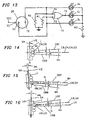
- Figure 13 is a schematic of the circuit comprising the components of circuit assembly 10.
- the primary components of circuit assembly 10 include:
- Figure 14 is a side view of lighting device 50 in the vertical position it would assume if the ship were in perfectly calm water.
- central beam means CM is energized emitting central beam CB having central axis CA.
- Central axis CA is coincident with central horizontal reference plane CH as well as selected direction SD.
- Selected direction SD represents the direction along which light is required to be projected from lighting device 50. The selected direction SD does not change with an angular tilt of lighting device 50. Light projected parallel to the selected direction SD will be considered directed in the selected direction SD.
- Selected direction SD forms angle A2 with tilt plane V2.
- angle A2 is 90 degrees making the selected direction parallel to the central horizontal reference plane CH, however, the selected direction can have a different value for other embodiments of the current invention.
- Figure 15 is a side view of lighting device 50 as it would appear if it were rotated counterclockwise to angle DA1 about tilt plane V2 due to a rolling of the ship in a first direction.
- Figure 16 is a side view of lighting device 50 as it would appear if it were rotated clockwise to angle UA1 about tilt plane V2 due to a rolling of the ship in a second and opposite direction.
- Resistor R3 is disposed between each LED lamp and ground to assure that each LED lamp draws the appropriate current. Neither upper LED lamp UL or downward LED lamp DL will be energized since neither downward terminal T1 or upward terminal T2 are connected to supply voltage VCC.
- Central LED lamp CL of central beam means CM is thus illuminated directing light into central optic CO.
- Central optic CO is typically a classical aspheric piano convex condensing lens with central LED lamp CL positioned substantially at its focal point CF. Thus light emerging from central optic CO will be formed into a central beam CB concentrated about central horizontal plane CH and about central beam axis CA.
- Central beam CB comprises central beam axis CA representing the direction of maximum beam intensity.
- Central beam CB further comprises central boundary top CBT and central boundary bottom CBB each representing directions equal to fifty percent of the maximum beam intensity. This embodiment would comply with a specification that required a minimum intensity which was fifty percent of the beam intensity of central beam CB.
- Central boundary top CBT and central boundary bottom CBB define the vertical beamspread of central beam CB which for the present embodiment is 2A1 degrees.
- Central beam axis CA bisects the vertical beamspread forming angle A1 between central beam axis CA and central boundary top CBT and angle A1 between central beam axis CA and central boundary bottom CBB.
- central boundary top CBT comprises a positive slope (i.e. it increases in value with distance along central horizontal plane CH and away from central optic CO).
- central boundary bottom CBB has a negative slope (i.e. it decreases in value with distance along central horizontal plane CH and away from central optic CO).
- central horizontal plane CH has a zero slope. If as in the current embodiment the selected direction SD is along the central horizontal plane then lighting device 50 must project light in the horizontal direction or equivalently parallel to any horizontal plane.
- power control means 8 should selectively energize the beam means which for an existing angular disposition of lighting device 50 relative to tilt plane V2 will direct light along a horizontal direction. This is achieved for the figure 14 disposition of lighting device 50 if power control means 8 energizes central beam means CM because the zero slope of central horizontal plane CH has a value between the positive slope of central boundary top CBT and the negative slope of central boundary bottom CBB.
- clockwise angle UA1 and angle A1 are all equal.
- the current invention can still be constructed if they are unequal however, the equality of angles simplifies the design.
- the current embodiment discloses a design which energizes the central beam means CM whenever the disposition of lighting device 50 is such that either the central boundary top CBT or the central boundary bottom CBB has a zero slope (i.e. it is horizontal).
- the central beam means CM continues to energize central beam means CM as lighting device 50 rotates until the remaining boundary achieves a zero slope (i.e. it becomes horizontal).
- the power control means 8 could in fact illuminate a selected beam means other that at the disposition of lighting device 50 where a boundary of the beam aligned with the selected direction.
- a selected beam means could be illuminated only after the selected direction was within the boundaries of the light beam.
- the current embodiment could also simultaneously illuminate more than one of the beam means.
- the design could possibly be improved if the power control means energized the selected beam means when selected direction was exterior to the beam.
- a number of factors can affect the relationship between the disposition of lighting device 50 and the appropriate time to energize a selected beam means by power control means 8. These factors include but are not limited to: response time of the beam means, response time of the power control means, tolerances of components, desirability of overlapping beams, etc.
- the central beam means CM will remain lighted only as long as the disposition of lighting device 50 is such that either a clockwise rotation does not equal or exceed angle UA1 or a counterclockwise rotation does not equal or exceed angle DA1. This configuration is easy to describe however it can be modified for other embodiments of the current invention if the aforementioned design factors so indicate.
- the functioning of the current invention can be described from another perspective.
- the current invention would be employed if power control means 8 extinguishes at least one of the beam means when that beam means is positioned such that its projected light beam would not include the selected direction within its boundaries.
- the power control means 8 can also be identified as a power control or a power control device.
- NOR gate 15 has NOR input terminal T3 connected to supply voltage VCC and NOR input terminal T4 at ground. This will cause NOR output terminal T5 to remain low and central LED lamp CL will not be energized. Since downward terminal T1 is connected to supply voltage VCC downward LED lamp DL will be energized. Resistor R1 is of a relatively high value and therefore will not create excess current or prevent supply voltage VCC from illuminating downward LED lamp DL. Since upward terminal T2 is not connected to supply voltage VCC upward LED lamp UL will not be energized.
- downward beam DB comprises downward beam axis DA representing the direction of maximum beam intensity.
- Downward beam DB further comprises downward boundary top DBT and downward boundary bottom DBB each representing directions equal to fifty percent of the maximum beam intensity.
- Downward boundary top DBT and downward boundary bottom DBB define the vertical beamspread of downward beam DB which for the present embodiment is 2A1 degrees.
- Downward beam axis DA bisects the vertical beamspread forming angle A1 between downward beam axis DA and downward boundary top DBT and angle A1 between downward beam axis DA and downward boundary bottom DBB. It is to be noted that at the figure 15 disposition of lighting device 50 downward boundary top DBT comprises a zero slope making it directed parallel to the selected direction SD.
- downward boundary bottom DBB has a negative slope (i.e. it decreases in value with distance along the downward horizontal reference plane DH and away from downward optic DO).
- power control means 8 will energize downward beam means DM.
- downward boundary top DBT of downward beam DB is parallel to selected direction SD.
- power control means 8 will continue to energize downward beam means DM.
- the slope of downward horizontal reference plane DH will be between the slope of downward boundary top DBT and downward boundary bottom DBB of downward beam DB.
- it will continue to project light from downward beam means DM which includes light projected parallel to downward horizontal reference plane DH and parallel to selected direction SD.
- switch axis SA of tilt switch 20 is as shown in figure 12 .
- common terminal TC is connected to upward terminal T2 thus applying supply voltage VCC to NOR input terminal T4.
- Common terminal TC is not connected to downward terminal T1. Therefore with resistor R1 NOR input terminal T3 is at ground potential.
- NOR gate 15 has NOR input terminal T4, connected to supply voltage VCC with NOR input terminal T3 connected to ground. This will cause NOR output terminal T5 to remain low and central LED lamp CL will not be energized.
- upward beam UB comprises upward beam axis UA representing the direction of maximum beam intensity.
- Upward beam UB further comprises upward boundary top UBT and upward boundary bottom UBB each representing directions equal to fifty percent of the maximum beam intensity.
- Upward boundary top UBT and upward boundary bottom UBB define the vertical beamspread of upward beam UB which for the present embodiment is 2A1 degrees.
- Upward beam axis UA bisects the vertical beamspread forming angle A1 between upward beam axis UA and upward boundary top UBT and angle A1 between upward beam axis UA and upward boundary bottom UBB.
- upward boundary top UBT comprises a positive slope (i.e. it increases in value with distance along upward horizontal reference plane UH and away from the upward optic UO).
- upward boundary bottom UBB has a zero slope making it parallel to the selected direction SD.
- lighting device 50 when lighting device 50 is rotated clockwise to angle UA1 relative to tilt plane V2 power control means 8 will energize upward beam means UM.
- upward boundary bottom UBB of the upward beam UB is parallel to selected direction SD.
- power control means 8 Upon further clockwise rotation of lighting device 50 relative to tilt plane V2 power control means 8 will continue to energize upward beam means UM.
- the zero slope of upward horizontal reference plane UH will be between the slope of upward boundary top UBT and upward boundary bottom UBB of upward beam UB.
- it will continue to project light from upward beam means UM which includes light projected parallel to upward horizontal reference plane UH or equivalently along selected direction SD.
- the vertical beamspread of the composite projected light beam is between upward boundary top UBT and downward boundary bottom DBB comprising a vertical beamspread of six times angle A1.
- the minimum intensity of the composite light beam will be fifty percent of the maximum intensity.
- the power control means energizes only the central beam means which is designed to project a light beam substantially centered about the horizontal plane. This horizontal light beam is desirable because it is visible to a distant observer on the horizontal plane. However, if the lighting device is tilted upward the power control means turns "off" the central beam means and energizes in its place the downward beam means.
- the downward beam means is designed to project a light beam downwardly diverging about the horizontal. This downward light beam would normally be useless as it would be directed into the water, however, due to the fact that the lighting device is tilted upward the downwardly directed light beam compensates for the upward tilt of the light to project the desired horizontal light beam.
- the power control means responds by turning "off" the downwardly directed beam means and energizes in its place the upwardly directed beam means.
- This upward beam means is designed to project a light beam upwardly diverging from the horizontal plane. This upwardly directed beam is normally useless as it would be directed into the sky and miss a horizontal observer. However, due to the fact that the lighting device is tilted downward the upward direction of the projected light beam compensates for the downward tilt of the light to maintain a projected light beam which is horizontal and thus visible to a distant observer.
- a single beam means having a very large angular beamspread in compliance with a specification minimum intensity would also require an unacceptable amount of power.
- the current invention employs a plurality of beam means disposed such that if they were simultaneously energized they would emit a plurality of light beams which would - due to their adjacent locations - combine to form a composite projected light beam of acceptable intensity throughout an acceptable vertical beamspread. In order to avoid an unacceptable drain of electrical power some of the beam means are not energized. Specifically those beam means which at a particular angular disposition of the lighting device about the vertical reference plane do not reasonably add to the visibility of the lighting device in the selected direction are turned "off" by the power control means.
- the current invention it is possible for several beam means to be simultaneously energized. This is acceptable if at least some of the beam means are - at times - turned "off" or extinguished resulting in a reduction in the power consumed by the lighting device.
- the power saved by extinguishing some of the beam means can by itself remain as a benefit of the current invention.
- the power saved can be used to increase the intensity of the horizontal light.
- the intensity of the horizontal light can be increased by increasing the intensity of a single selectively energized beam means by using a more powerful light source or by employing a group of beam means all projecting light substantially within the same vertical angular beamspread and all simultaneously energized by the power control means. Increasing the intensity of the horizontal light can substantially add to the visibility of the lighting device and can be a greater benefit than a reduction in power.
- angular range represents the roll or vertical angular tilt that the lighting device is expected to experience.
- the beam means used to form the lighting device can be designed. If a single beam means is employed to cover the entire angular range the design is classical prior art. If on the other hand a plurality of beam means each of which lights a portion of the vertical angular range is cooperatively employed with a power control means designed to selectively energize one or more - but not all - of the beam means in response to the angular tilt of the lighting device then the current invention is employed.
- each of the beam means is required to project its beam of light into a portion of the vertical angular range.
- the angular range is ten degrees and there are two beam means then a first beam means would be designed to project a first light beam to fill the range of vertical beamspread extending from zero to five degrees and a second beam means would be designed to project a second light beam to fill the range of vertical beamspread extending from five to ten degrees.
- the vertical angular range could be filled by a larger number of beam means. For example if there were ten beam means each of these would be designed to fill only one vertical degree of the ten degree vertical angular range. Thus the first beam means would only be designed to project its light beam extending from zero to one degree. The second beam means would be designed to project its light beam extending from one to two degrees. The design would continue until the ten beam means when energized would fill the entire ten degree range of vertical angular beamspread. However, for some embodiments of the current invention at least some of the beam means which were not disposed to project light parallel to the selected direction would at times not be energized so that power would be saved.
- the preferred embodiment shows LED lamps as the light sources however other electronic light sources such as electroluminescent panels or LED elements or even incandescent lamps can be employed.
- Electronic light sources are especially useful when the lighting device is rocking back and forth about a vertical reference plane.
- Solid state electronic lamps respond almost instantaneously and are an excellent means of assuring that each light source commences emitting its projected light beam in the selected direction almost at the instant that the power control means energizes the lamp.
- Solid state electronic lamps respond almost instantaneously and are an excellent means of assuring that each light source commences emitting its projected light beam in the selected direction almost at the instant that the power control means energizes the lamp.
- Other dynamic applications could not employ an incandescent lamp.
- the current invention can be successfully constructed by using a variety of components other then those identified herein.
- the LED lamps disclosed have a lens top body or encapsulating refractor which concentrates the light emitted by the internal LED element.
- each LED lamp projected its light into a lens which further concentrated the light in the vertical plane.
- LED elements can be used without the encapsulating refractor employed in the disclosed commercial T 1 3/4 lens top LED lamp. Also other lens shapes can be used. Additionally, electroluminescent strips can be employed as the light sources. Finally, incandescent lamps with reflectors or refractors can be acceptable for some uses. Actually, many beam means which project a beam of light can function acceptably with the power control means of the current invention.
- the preferred embodiments of the current invention described a lighting device that maintained a horizontally directed light beam throughout an angular displacement of the lighting device about the vertical plane. This would be a frequent objective of the current invention.
- the invention is not limited to designs requiring a horizontally projected light beam. In fact the design can be easily modified to maintain a projected light beam at any angle relative to the vertical.
- Figures 17 thru 24 to be hereinafter presented describe lighting device 50A which comprises a selected direction angled downward about the horizontal.
- FIGS 17 thru 24 represent lighting device 50A an alternate embodiment of the current invention which employs two beam means in place of the three beam means employed in lighting device 50. Additionally, each of the two beam means each create their respective projected light beams without employing the separate optical lens employed in lighting device 50. Also in lighting device 50A upward LED lamp ULA and downward LED lamp DLA each have an integral refracting lens molded around their LED elements as found in standard commercial LED lamps such as the T 1 3/4 package. For some uses this type of lamp or other lamps of similar construction can be used without a separate optic. Lighting device 50A additionally represents an embodiment which does not require the housing employed in lighting device 50.
- lighting device 50A Components of lighting device 50A which are similar in function to components described for lighting device 50 are identified with the suffix A added to the basic identifying number used for lighting device 50. Components not previously employed have a new identification number also with the suffix A. In general lighting device 50A functions in a fashion similar to lighting device 50 previously described. However a brief description of the operation of lighting device 50A discloses some additional features not previously disclosed.
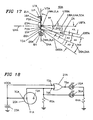
- Figure 17 is a side view of lighting device 50A in a vertical position.
- FIG 18 is an electrical schematic of the circuit employed to energize lighting device 50A.
- Lighting device 50A comprises circuit assembly 10A mounted on or supported by circuit board 16A.
- Circuit board 16A comprises upper hole 17A.
- Upper screw 11A passes through upper hole 17A and can be threaded into a ships bulkhead - not shown - to secure or fasten lighting device 50A to the bulkhead. As the ship rolls the angular position of lighting device 50A relative to vertical tilt plane V2A will change.
- Circuit assembly 10A comprises upward LED lamp ULA, downward LED lamp DLA, battery 23A, resistor R4A and power control means 8A.
- Power control means 8A includes tilt switch 20A, resistor R5A and exclusive OR gate 21A.
- Circuit board 16A comprises circuit tracks 22A for electrically connecting the components of circuit assembly 10A in accordance with the schematic of figure 18 .
- a 6 volt battery 23A is soldered to circuit tracks 22A of circuit board 16A using positive power line P1A and negative power line P2A.
- Circuit board 16A thus acts as a means to electrically connect circuit assembly 10A and also as a support means for its components.
- Circuit board 16A also supports the upward beam means UMA and downward beam means DMA in a fixed relationship such that each of their projected light beams is positioned to cooperate to achieve the objective of the current invention which is to efficiently project light parallel to or in a selected direction SDA.
- Lighting device 50A is constructed to project light in a selected direction SDA throughout a range of angular displacement of lighting device 50A relative to tilt plane V2A resulting from the rolling of the ship.
- the selected direction SDA for the lighting device 50A embodiment of the current invention intersects vertical tilt plane V2A forming obtuse angle A4.
- the selected direction SDA of lighting device 50A has a negative slope or is directed below upward horizontal reference plane UHA.
- upward beam means UMA projects an upward (relative to the other beam means) light beam UBA with a vertical angular beamspread of angle 2A3.
- Upward beam axis UAA bisects upward beam UBA forming angle A3 between upward beam axis UAA and upward boundary top UBTA.
- Upward beam axis UAA similarly forms angle A3 between upward beam axis UAA and upward boundary bottom UBBA.
- Upward beam axis UAA is coincident with selected direction SDA.
- Downward beam means DMA is similar to upward beam means UMA except that it is directed at an oblique angle relative to upward beam means UMA.
- Downward beam means DMA projects a downward beam DBA also with a vertical angular beamspread of angle 2A3.
- Downward beam axis DAA bisects downward beam DBA forming angle A3 between downward beam axis DAA and downward boundary top DBTA.
- Downward beam axis DAA similarly forms angle A3 between downward beam axis DAA and downward boundary bottom DBBA.
- Overlap zone ZA can be a desirable feature to avoid dark zones between projected beams which can result from manufacturing tolerances relating to the vertical beamspread, the actual positions of the plurality of beam means, variations within the power control means or time lags between the energizing and illuminating of a beam means.
- Downward beam axis DAA forms angle A5 with upward beam axis UAA. Angle A5 is slightly less than angle 2A3 with the difference related to the magnitude of the overlap zone ZA.
- Lighting device 50A is constructed with a consistency and symmetry of beamwidths. This facilitates the construction and description.
- the current invention can also be constructed with each beam means having unbalanced vertical beamspreads about its beam axis and with different beamspreads for each of the plurality of projected light beams.
- the selected direction SDA is shown as coincident with the upward beam axis UBA. This is also a parameter that can be changed within the scope of the current invention. Contingent upon factors including the intensity required to be maintained along the selected direction and the vertical intensity profile of each projected beam pattern the location of the selected direction within a particular projected beam for a particular angular disposition of the lighting device about tilt plane V2A can be varied.
- the selected direction SDA falls between the top boundary and the bottom boundary of the projected light beam some light will be projected along the selected direction.
- the intensity of that projected light must be adequate to comply with the particular specification if the overall design is to be acceptable.
- the intensity of the projected light along the selected direction we are considering the intensity of the projected light along the selected direction as adequate if the selected direction is within the boundaries of any of the light beams which lighting device 50A can emit. If both beam means are illuminated, the projected light beams combine to form a composite light beam diverging above and below the selected direction SDA.
- the current embodiment of the current invention employs a power control means 8A which selectively energizes only one of the beam means.
- the power control means 8A selectively energizes the beam means which will - when energized - project light along or parallel to the selected direction.
- Figure 19 is a side view of lighting device 50A similar to figure 17 except in figure 19 only upward beam means UMA is energized.
- Figure 20 is a side view of tilt switch 20A from figure 19 .
- Resistor R5A is of a relatively high value such that it brings exclusive OR input terminal T4A to ground when supply voltage VCCA is not applied to exclusive OR input terminal T4A but does not draw enough current to prevent supply voltage VCCA from energizing LED lamp DLA when it is applied to downward terminal T1A.
- Exclusive OR output terminal T5A will be high when only one of the exclusive OR gate 21A input terminals T3A and T4A is high. Therefore for the figure 19 disposition of lighting device 50A output terminal T5A of exclusive OR gate 21A, is high and upward LED lamp ULA is energized. Since downward terminal T1A is not connected to supply voltage VCCA, downward LED lamp DLA is not energized.
- Resistor R4A is in series with upward LED lamp ULA and downward LED lamp DLA to assure that they draw the appropriate current for their type of lamp.
- clockwise angle DA3A is equal to angle A3.
- Figure 23 is a side view of lighting device 50A rotated counterclockwise about tilt plane V2A to counterclockwise angle UA3A and figure 24 is a side view of tilt switch 20A from figure 23 .
- counterclockwise angle UA3A is equal to angle A3.
- a further counterclockwise rotation of lighting device 50A of approximately 2A3 degrees will not alter the current flow in circuit assembly 10A and downward beam means DMA will remain energized. Also throughout most, but not necessarily all, of this additional counterclockwise rotation selected direction SDA will fall between downward boundary top DBTA and downward boundary bottom DBBA of downward beam DBA. Thus lighting device 50A will project a light beam which includes light directed along the selected direction SDA throughout a vertical range of movement of slightly less than four times angle A3.
- Figure 25 is a perspective view of a type of commercially available incandescent lamp 24 and reflector 25 which can substitute for the upward means UMA and the downward means DMA of figure 23 .
Landscapes
- Engineering & Computer Science (AREA)
- General Engineering & Computer Science (AREA)
- Mechanical Engineering (AREA)
- Chemical & Material Sciences (AREA)
- Combustion & Propulsion (AREA)
- Ocean & Marine Engineering (AREA)
- Radar, Positioning & Navigation (AREA)
- Remote Sensing (AREA)
- Lighting Device Outwards From Vehicle And Optical Signal (AREA)
Claims (18)
- Elektrische Beleuchtungsvorrichtung (50) umfassend :eine Vielzahl von Lichtstrahlmitteln (UM, CM, DM), welche mit einer elektrischen Stromquelle verbindbar sind, die eine Spannung aufweist, wobei jedes der Lichtstrahlmittel eine Lichtquelle (UL, CL, DL) zum Aussenden jeweils eines Lichtstrahls (UB, CB, DB) beim Anlegen der Spannung an die jeweilige Lichtquelle umfasst; dadurch gekennzeichnet, dasssie ferner eine Schaltungsanordnung (10) umfasst, welche die Vielzahl von Lichtstrahlmitteln und Mittel zum Steuern der Leistung (8) umfasst;wobei die Schaltkreisvorrichtung (10) wenigstens teilweise auf einem Träger (16A) so angeordnet ist, dass die Lichtstrahlen (UB, CB, DB) divergieren; unddie Mittel zum Steuern der Leistung (8) geeignet ausgebildet sind, um die Spannung in Abhängigkeit von einer angularen Divergenz zwischen dem Lichtstrahl und der horizontalen Ebene wahlweise an wenigstens eines der Lichtstrahlmittel (UM, CM, DM) anzulegen.
- Elektrische Beleuchtungsvorrichtung (50) nach Anspruch 1, wobei zwei Strahlmittel (UM, DM) vorgesehen sind.
- Elektrische Beleuchtungsvorrichtung (50) nach Anspruch 1, wobei drei Strahlmittel (UM, CM, GM) vorgesehen sind.
- Elektrische Beleuchtungsvorrichtung (50) nach Anspruch 1, wobei die Mittel zum Steuern der Leistung (8) ferner einen Neigungsschalter (20) umfassen.
- Elektrische Beleuchtungsvorrichtung (50) nach Anspruch 4, wobei der Neigungsschalter (20) einen ersten Schalter aufweist, der auf eine erste Winkelstellung des Neigungsschalters anspricht und einen zweiten Schalter, der auf eine zweite Winkelstellung des Neigungsschalters (20) anspricht.
- Elektrische Beleuchtungsvorrichtung (50) nach Anspruch 1, wobei die Mittel zum Steuern der Leistung (8) ferner einen Schwerkraftschalter umfassen.
- Elektrische Beleuchtungsvorrichtung (50) nach Anspruch 1, wobei die Lichtstrahlen (UB, CB, DB) sich, wenn sie gebildet werden, zur Bildung eines zusammengesetzten Lichtstrahles zusammensetzen.
- Elektrische Beleuchtungsvorrichtung (50) nach Anspruch 7, wobei jeder Lichtstrahl (UB, CB, DB) eine vertikale Strahlaufweitung besitzt, und der zusammengesetzte Lichtstrahl eine vertikale Strahlaufweitung besitzt, die grösser ist als die vertikale Strahlaufweitung von jedem einzelnen der Lichtstrahlen.
- Elektrische Beleuchtungsvorrichtung (50) nach Anspruch 1, wobei jede Lichtquelle (UL, CL, DL) jeweils eine Leuchtdiode oder LED, besitzt.
- Elektrische Beleuchtungsvorrichtung (50) nach Anspruch 1, wobei jede Lichtquelle (UL, CL , DL) jeweils eine LED-Lampe besitzt.
- Elektrische Beleuchtungsvorrichtung (50) nach Anspruch 1, wobei jede Lichtquelle (UL, CL, DL) jeweils eine Glühlampe (24) besitzt.
- Elektrische Beleuchtungsvorrichtung (50) nach Anspruch 1, wobei jedes Strahlmittel (UM, CM, DM) eine Linse (UO, CO, DO) aufweist, die so angeordnet ist, dass sie den Lichtstrahl (UB, CB, DB), der von der Lichtquelle (UL, CL, DL) ausgesendet wird, konzentriert.
- Elektrische Beleuchtungsvorrichtung (50) nach Anspruch 1, wobei jedes Strahlmittel (UM, CM, DM) einen Reflektor (25) aufweist, der so angeordnet ist, dass er den von der Lichtquelle ausgesendeten Lichtstrahl konzentriert.
- Elektrische Beleuchtungsvorrichtung (50) nach Anspruch 1, wobei die Schaltungsanordnung ferner die elektrische Spannungsquelle (23A) umfasst.
- Elektrische Beleuchtungsvorrichtung (50) nach Anspruch 14, wobei die Mittel zum Steuern der Leistung (8) Neigungsschalter (20) aufweisen, von denen jeweils einer zwischen den Lichtstrahlmitteln (UM, CM, DM) und der elektrischen Spannungsquelle (23A) angeschlossen ist, wobei die Mittel zum Steuern der Leistung (8) auf eine vertikale Winkelstellung des Trägers in Bezug auf eine vertikale Ebene ansprechen, und wobei die Mittel zum Steuern der Leistung jeden der Neigungsschalter bei einer vorbestimmten vertikalen Winkelstellung des Trägers schalten, sodass in Abhängigkeit von der vertikalen Winkelstellung des Trägers Spannung an jeweils eines der Lichtstrahlmittel (UM, CM, DM) geliefert wird.
- Elektrische Beleuchtungsvorrichtung (50) nach Anspruch 15, wobei zwei Lichtstrahlmittel (UM, DM) vorgesehen sind.
- Elektrische Beleuchtungsvorrichtung (50) nach Anspruch 15, wobei drei Lichtstrahlmittel (UM, CM, DM) vorgesehen sind.
- Verfahren zum Bereitstellen eines Lichtstrahls (UB, CB, DB) in einer horizontalen Ebene unabhängig von der vertikalen Winkeklstellung eines Trägers (16A), auf dem eine den Lichtstrahl erzeugende elektrische Beleuchtungsvorrichtung (50) befestigt ist, umfassend die Schritte :Bereitstellen der elektrischen Beleuchtungsvorrichtung (50), die mit einer elektrischen Spannungsquelle verbindbar ist, und einer Vielzahl von Lichtstrahlmitteln (UM, CM, DM), wobei jedes dieser Lichtstrahlmittel eine Lichtquelle (UL, CL, DL) besitzt, um beim Anlegen einer elektrischen Spannung an die jeweilige Lichtquelle (UL, CL, DL) jeweils einen Lichtstahl (UB, CB, DB) zu erzeugen,Bereitstellen einer Schaltungsanordnung (10), welche die Vielzahl von Lichtstrahlmitteln (UM, CM, DM) und Mittel zum Steuern der Leistung (8) besitzt, wobei die Mittel zum Steuern der Leistung (8) einen Neigungsschalter (20) besitzen, der auf die vertikale Winkelstellung des Trägers (16A) anspricht, und wobei die Schaltungsanordnung (10) wenigstens teilweise auf dem Träger (16A) angeordnet ist, so dass die Lichtstrahlen (UB, ZB, DB) divergieren,Anlegen einer elektrischen Spannung an ausgewählte Lichtstrahlmittel (UM, CM, DM) um den Lichtstrahl (UB, CB, DB) in der horizontalen Ebene zu erzeugen,Entfernen der elektrischen Spannung von den ausgewählten Lichtstrahlmitteln, wenn die vertikale Winkelstellung des Trägers (16A) sich verändert und Anlegen der elektrischen Spannung der Reihe nach an ausgewählte Lichtstrahlmittel (UM, CM, DM) in Abhängigkeit von der vertikalen Winkelstellung des Trägers, wobei der horizontale Lichtstrahl bereitgestellt wird.
Priority Applications (3)
| Application Number | Priority Date | Filing Date | Title |
|---|---|---|---|
| US09/097,798 US6030099A (en) | 1998-06-16 | 1998-06-16 | Selected direction lighting device |
| DE69939174T DE69939174D1 (de) | 1998-06-16 | 1999-12-08 | Beleuchungsvorrichtung mit gegebener Beleuchtungsrichtung |
| EP99124455A EP1106432B1 (de) | 1998-06-16 | 1999-12-08 | Beleuchungsvorrichtung mit gegebener Beleuchtungsrichtung |
Applications Claiming Priority (2)
| Application Number | Priority Date | Filing Date | Title |
|---|---|---|---|
| US09/097,798 US6030099A (en) | 1998-06-16 | 1998-06-16 | Selected direction lighting device |
| EP99124455A EP1106432B1 (de) | 1998-06-16 | 1999-12-08 | Beleuchungsvorrichtung mit gegebener Beleuchtungsrichtung |
Publications (2)
| Publication Number | Publication Date |
|---|---|
| EP1106432A1 EP1106432A1 (de) | 2001-06-13 |
| EP1106432B1 true EP1106432B1 (de) | 2008-07-23 |
Family
ID=26153191
Family Applications (1)
| Application Number | Title | Priority Date | Filing Date |
|---|---|---|---|
| EP99124455A Expired - Lifetime EP1106432B1 (de) | 1998-06-16 | 1999-12-08 | Beleuchungsvorrichtung mit gegebener Beleuchtungsrichtung |
Country Status (3)
| Country | Link |
|---|---|
| US (1) | US6030099A (de) |
| EP (1) | EP1106432B1 (de) |
| DE (1) | DE69939174D1 (de) |
Cited By (1)
| Publication number | Priority date | Publication date | Assignee | Title |
|---|---|---|---|---|
| US8870419B2 (en) | 2009-09-17 | 2014-10-28 | Koninklijke Philips N.V. | Lighting system with gravity controlled light beam |
Families Citing this family (88)
| Publication number | Priority date | Publication date | Assignee | Title |
|---|---|---|---|---|
| US8093823B1 (en) | 2000-02-11 | 2012-01-10 | Altair Engineering, Inc. | Light sources incorporating light emitting diodes |
| US7049761B2 (en) | 2000-02-11 | 2006-05-23 | Altair Engineering, Inc. | Light tube and power supply circuit |
| US6323781B1 (en) * | 2000-08-22 | 2001-11-27 | Power Signal Technologies | Electronically steerable light output viewing angles for traffic signals |
| US6598998B2 (en) | 2001-05-04 | 2003-07-29 | Lumileds Lighting, U.S., Llc | Side emitting light emitting device |
| GB2377986A (en) * | 2001-07-16 | 2003-01-29 | Mathmos Ltd | Lighting apparatus responsive to spatial orientation |
| US6742918B2 (en) * | 2002-04-12 | 2004-06-01 | Guide Corporation | Movable condenser lens |
| US6679621B2 (en) | 2002-06-24 | 2004-01-20 | Lumileds Lighting U.S., Llc | Side emitting LED and lens |
| US6896381B2 (en) * | 2002-10-11 | 2005-05-24 | Light Prescriptions Innovators, Llc | Compact folded-optics illumination lens |
| US7042655B2 (en) * | 2002-12-02 | 2006-05-09 | Light Prescriptions Innovators, Llc | Apparatus and method for use in fulfilling illumination prescription |
| US6924943B2 (en) * | 2002-12-02 | 2005-08-02 | Light Prescriptions Innovators, Llc | Asymmetric TIR lenses producing off-axis beams |
| US7377671B2 (en) | 2003-02-04 | 2008-05-27 | Light Prescriptions Innovators, Llc | Etendue-squeezing illumination optics |
| GB2400903A (en) * | 2003-04-24 | 2004-10-27 | Stephen Walker | Light source for boat's navigation lamp |
| DE10318932A1 (de) * | 2003-04-26 | 2004-11-25 | Aqua Signal Aktiengesellschaft Spezialleuchtenfabrik | Laterne, vorzugsweise für die Verwendung an Bord von Schiffen, insbesondere auf Sportbooten |
| US7021797B2 (en) * | 2003-05-13 | 2006-04-04 | Light Prescriptions Innovators, Llc | Optical device for repositioning and redistributing an LED's light |
| US7329029B2 (en) * | 2003-05-13 | 2008-02-12 | Light Prescriptions Innovators, Llc | Optical device for LED-based lamp |
| US8075147B2 (en) * | 2003-05-13 | 2011-12-13 | Light Prescriptions Innovators, Llc | Optical device for LED-based lamp |
| WO2005012951A2 (en) * | 2003-07-28 | 2005-02-10 | Light Prescriptions Innovators, Llc | Three-dimensional simultaneous multiple-surface method and free-form illumination-optics designed therefrom |
| WO2005012952A2 (en) * | 2003-07-29 | 2005-02-10 | Light Prescriptions Innovators, Llc | Circumferentially emitting luminaires and lens elements formed by transverse-axis profile-sweeps |
| EP1671061A4 (de) * | 2003-09-16 | 2007-12-12 | Vega Ind Ltd | Verbesserungen von segmentierten lampen |
| US20060082221A1 (en) * | 2003-10-03 | 2006-04-20 | Alexander Mouzas | Vehicle sidelight control system |
| US20050146875A1 (en) * | 2004-01-07 | 2005-07-07 | Tideland Signal Corporation | Side-emitting led marine signaling device |
| CN101326553B (zh) * | 2005-05-09 | 2011-11-30 | Bwt产权公司 | 具有精确光束控制的光信号装置 |
| US7420663B2 (en) * | 2005-05-24 | 2008-09-02 | Bwt Property Inc. | Spectroscopic sensor on mobile phone |
| US7357530B2 (en) * | 2005-07-15 | 2008-04-15 | Bwt Property, Inc. | Lighting apparatus for navigational aids |
| US8631787B2 (en) * | 2005-07-28 | 2014-01-21 | Light Prescriptions Innovators, Llc | Multi-junction solar cells with a homogenizer system and coupled non-imaging light concentrator |
| US8419232B2 (en) * | 2005-07-28 | 2013-04-16 | Light Prescriptions Innovators, Llc | Free-form lenticular optical elements and their application to condensers and headlamps |
| JP2009503793A (ja) * | 2005-07-28 | 2009-01-29 | ライト プレスクリプションズ イノベーターズ エルエルシー | バックライトおよびフロントライト用のエテンデュ保存型照明光学部品 |
| DE102005049410B4 (de) * | 2005-10-13 | 2007-09-27 | Aqua Signal Aktiengesellschaft | Positionslaterne |
| US7367686B2 (en) * | 2005-10-14 | 2008-05-06 | Aqua Signal Aktiengesellschaft | Position lamp for use with watercraft and ashore and having multiple light sources |
| US20070127258A1 (en) * | 2005-12-07 | 2007-06-07 | Bwt Property, Inc. | Projection lighting apparatus for marking and demarcation |
| US7545493B2 (en) * | 2005-12-23 | 2009-06-09 | Bwt Property, Inc. | Raman spectroscopic apparatus utilizing internal grating stabilized semiconductor laser with high spectral brightness |
| US8174482B1 (en) * | 2005-12-31 | 2012-05-08 | Hewlett-Packard Development Company, L.P. | Techniques to control brightness in a display |
| US7755513B2 (en) * | 2006-01-13 | 2010-07-13 | Bwt Property, Inc. | Visual navigational aids based on high intensity LEDS |
| US7804251B2 (en) * | 2006-04-10 | 2010-09-28 | Bwt Property Inc. | LED signaling apparatus with infrared emission |
| US8709056B2 (en) * | 2006-04-10 | 2014-04-29 | Bwt Property Inc | Phototherapy apparatus with built-in ultrasonic image module |
| WO2008008994A2 (en) * | 2006-07-14 | 2008-01-17 | Light Prescriptions Innovators, Llc | Brightness-enhancing film |
| WO2008022064A2 (en) * | 2006-08-10 | 2008-02-21 | Light Prescriptions Innovators, Llc | Led light recycling device |
| WO2008022065A2 (en) * | 2006-08-11 | 2008-02-21 | Light Prescriptions Innovators, Llc | Led luminance-enhancement and color-mixing by rotationally multiplexed beam-combining |
| US7800122B2 (en) * | 2006-09-07 | 2010-09-21 | Hong Kong Applied Science And Technology Research Institute Co., Ltd. | Light emitting diode device, and manufacture and use thereof |
| US7854616B2 (en) * | 2007-10-12 | 2010-12-21 | The L.D. Kichler Co. | Positionable lighting systems and methods |
| US8118447B2 (en) | 2007-12-20 | 2012-02-21 | Altair Engineering, Inc. | LED lighting apparatus with swivel connection |
| US7712918B2 (en) | 2007-12-21 | 2010-05-11 | Altair Engineering , Inc. | Light distribution using a light emitting diode assembly |
| CN102016402A (zh) * | 2008-02-21 | 2011-04-13 | 光处方革新有限公司 | 球形发射远距离磷光体 |
| DE102008022344A1 (de) * | 2008-04-30 | 2009-11-05 | Siemens Aktiengesellschaft | Lichtsignal |
| US8360599B2 (en) | 2008-05-23 | 2013-01-29 | Ilumisys, Inc. | Electric shock resistant L.E.D. based light |
| US7976196B2 (en) | 2008-07-09 | 2011-07-12 | Altair Engineering, Inc. | Method of forming LED-based light and resulting LED-based light |
| US7946729B2 (en) | 2008-07-31 | 2011-05-24 | Altair Engineering, Inc. | Fluorescent tube replacement having longitudinally oriented LEDs |
| US8674626B2 (en) | 2008-09-02 | 2014-03-18 | Ilumisys, Inc. | LED lamp failure alerting system |
| US8256924B2 (en) | 2008-09-15 | 2012-09-04 | Ilumisys, Inc. | LED-based light having rapidly oscillating LEDs |
| US7938562B2 (en) | 2008-10-24 | 2011-05-10 | Altair Engineering, Inc. | Lighting including integral communication apparatus |
| US8653984B2 (en) | 2008-10-24 | 2014-02-18 | Ilumisys, Inc. | Integration of LED lighting control with emergency notification systems |
| US8324817B2 (en) | 2008-10-24 | 2012-12-04 | Ilumisys, Inc. | Light and light sensor |
| US8214084B2 (en) | 2008-10-24 | 2012-07-03 | Ilumisys, Inc. | Integration of LED lighting with building controls |
| US8444292B2 (en) | 2008-10-24 | 2013-05-21 | Ilumisys, Inc. | End cap substitute for LED-based tube replacement light |
| US8901823B2 (en) | 2008-10-24 | 2014-12-02 | Ilumisys, Inc. | Light and light sensor |
| US8556452B2 (en) | 2009-01-15 | 2013-10-15 | Ilumisys, Inc. | LED lens |
| US8362710B2 (en) | 2009-01-21 | 2013-01-29 | Ilumisys, Inc. | Direct AC-to-DC converter for passive component minimization and universal operation of LED arrays |
| US8664880B2 (en) | 2009-01-21 | 2014-03-04 | Ilumisys, Inc. | Ballast/line detection circuit for fluorescent replacement lamps |
| WO2010115183A1 (en) * | 2009-04-03 | 2010-10-07 | Virwall Systems, Inc. | Flexible ultraviolet led sanitizing apparatus |
| US8330381B2 (en) | 2009-05-14 | 2012-12-11 | Ilumisys, Inc. | Electronic circuit for DC conversion of fluorescent lighting ballast |
| US8299695B2 (en) | 2009-06-02 | 2012-10-30 | Ilumisys, Inc. | Screw-in LED bulb comprising a base having outwardly projecting nodes |
| CA2765200A1 (en) | 2009-06-23 | 2011-01-13 | Altair Engineering, Inc. | Illumination device including leds and a switching power control system |
| US9045082B2 (en) * | 2010-02-08 | 2015-06-02 | Innovative Lighting, Inc. | Non-invasive high intensity LED docking light and method for mounting |
| WO2011119958A1 (en) | 2010-03-26 | 2011-09-29 | Altair Engineering, Inc. | Inside-out led bulb |
| WO2011119921A2 (en) | 2010-03-26 | 2011-09-29 | Altair Engineering, Inc. | Led light with thermoelectric generator |
| CA2794512A1 (en) | 2010-03-26 | 2011-09-29 | Ilumisys, Inc. | Led light tube with dual sided light distribution |
| US8662705B2 (en) | 2010-03-30 | 2014-03-04 | Virwall Systems, Inc. | Flexible ultraviolet LED sanitizing apparatus |
| US8454193B2 (en) | 2010-07-08 | 2013-06-04 | Ilumisys, Inc. | Independent modules for LED fluorescent light tube replacement |
| CA2803267A1 (en) | 2010-07-12 | 2012-01-19 | Ilumisys, Inc. | Circuit board mount for led light tube |
| EP2633227B1 (de) | 2010-10-29 | 2018-08-29 | iLumisys, Inc. | Mechanismen zur minimierung des risikos von elektroschocks während der installation einer lichtröhre |
| US8870415B2 (en) | 2010-12-09 | 2014-10-28 | Ilumisys, Inc. | LED fluorescent tube replacement light with reduced shock hazard |
| US8902062B2 (en) * | 2011-01-27 | 2014-12-02 | Honeywell International Inc. | Systems and methods for detection of device displacement and tampering |
| WO2013028965A2 (en) | 2011-08-24 | 2013-02-28 | Ilumisys, Inc. | Circuit board mount for led light |
| US9184518B2 (en) | 2012-03-02 | 2015-11-10 | Ilumisys, Inc. | Electrical connector header for an LED-based light |
| DE102012203748A1 (de) * | 2012-03-09 | 2013-09-12 | Zumtobel Lighting Gmbh | LED-Lampe und Verfahren zum Betreiben einer derartigen Lampe |
| WO2014008463A1 (en) | 2012-07-06 | 2014-01-09 | Ilumisys, Inc. | Power supply assembly for led-based light tube |
| US9271367B2 (en) | 2012-07-09 | 2016-02-23 | Ilumisys, Inc. | System and method for controlling operation of an LED-based light |
| US9285084B2 (en) | 2013-03-14 | 2016-03-15 | Ilumisys, Inc. | Diffusers for LED-based lights |
| US9267650B2 (en) | 2013-10-09 | 2016-02-23 | Ilumisys, Inc. | Lens for an LED-based light |
| WO2015112437A1 (en) | 2014-01-22 | 2015-07-30 | Ilumisys, Inc. | Led-based light with addressed leds |
| US9510400B2 (en) | 2014-05-13 | 2016-11-29 | Ilumisys, Inc. | User input systems for an LED-based light |
| US10161568B2 (en) | 2015-06-01 | 2018-12-25 | Ilumisys, Inc. | LED-based light with canted outer walls |
| DE202015106996U1 (de) * | 2015-12-22 | 2017-03-23 | Zweibrüder Optoelectronics Gmbh & Co. Kg | Kopf- oder Taschenlampe |
| JP6804213B2 (ja) * | 2016-04-15 | 2020-12-23 | 株式会社小糸製作所 | 車両用灯具、および当該車両用灯具を備えた車両 |
| AU2017306706B2 (en) | 2016-08-05 | 2021-02-25 | Signify Holding B.V. | Lighting device led module with effects for beam spread tuning and beam shaping |
| US10696211B2 (en) * | 2018-04-27 | 2020-06-30 | Federal Signal Corporation | Lighting devices and systems with orientation detection and control |
| US11679171B2 (en) | 2021-06-08 | 2023-06-20 | Steribin, LLC | Apparatus and method for disinfecting substances as they pass through a pipe |
| CA3258541A1 (en) * | 2022-06-10 | 2023-12-14 | Polaris Industries Inc. | ADAPTIVE LIGHTING FOR A WATERCRAFT |
Family Cites Families (11)
| Publication number | Priority date | Publication date | Assignee | Title |
|---|---|---|---|---|
| ES459694A1 (es) * | 1976-06-19 | 1978-05-01 | Lucas Industries Ltd | Sistema de iluminacion para un vehiculo a motor. |
| US4325190A (en) * | 1980-08-25 | 1982-04-20 | Thomas Duerst | Bow sight |
| DE3208406C2 (de) * | 1982-03-09 | 1985-09-19 | Konrad 6831 Brühl Möbus | Neigungswaage mit Schaltröhre |
| US4654629A (en) * | 1985-07-02 | 1987-03-31 | Pulse Electronics, Inc. | Vehicle marker light |
| US5003443A (en) * | 1990-08-01 | 1991-03-26 | Sabala Edwin K | Illuminated display apparatus |
| US5101326A (en) * | 1990-09-27 | 1992-03-31 | The Grote Manufacturing Co. | Lamp assembly for motor vehicle |
| US5325271A (en) * | 1992-06-10 | 1994-06-28 | Dominion Automotive Industries Corp. | Marker lamp with LED array and prismatic diffuser |
| US5585783A (en) * | 1994-06-28 | 1996-12-17 | Hall; Roger E. | Marker light utilizing light emitting diodes disposed on a flexible circuit board |
| US5750974A (en) * | 1995-04-13 | 1998-05-12 | Keyence Corporation | Lighting apparatus having light emitting diodes arranged in a plurality of planes on a printed circuit board |
| JP3228864B2 (ja) * | 1995-12-13 | 2001-11-12 | アルプス電気株式会社 | 発光装置およびその製造方法 |
| CN2289944Y (zh) * | 1997-01-02 | 1998-09-02 | 俞志龙 | 一种标记灯灯泡 |
-
1998
- 1998-06-16 US US09/097,798 patent/US6030099A/en not_active Expired - Lifetime
-
1999
- 1999-12-08 EP EP99124455A patent/EP1106432B1/de not_active Expired - Lifetime
- 1999-12-08 DE DE69939174T patent/DE69939174D1/de not_active Expired - Lifetime
Cited By (1)
| Publication number | Priority date | Publication date | Assignee | Title |
|---|---|---|---|---|
| US8870419B2 (en) | 2009-09-17 | 2014-10-28 | Koninklijke Philips N.V. | Lighting system with gravity controlled light beam |
Also Published As
| Publication number | Publication date |
|---|---|
| US6030099A (en) | 2000-02-29 |
| EP1106432A1 (de) | 2001-06-13 |
| DE69939174D1 (de) | 2008-09-04 |
Similar Documents
| Publication | Publication Date | Title |
|---|---|---|
| US6030099A (en) | Selected direction lighting device | |
| US5890794A (en) | Lighting units | |
| US5608290A (en) | LED flashing lantern | |
| US5594433A (en) | Omni-directional LED lamps | |
| JP3065550B2 (ja) | 多光源ランプ及びそのランプを用いた表示灯 | |
| US5929788A (en) | Warning beacon | |
| US6086218A (en) | Portable flashing signal light | |
| US4344110A (en) | Supplemental identification system for channel and similar marker lights | |
| US5006971A (en) | Low power safety flasher | |
| CA1290008C (en) | Automotive headlamp dimming system | |
| US20040057234A1 (en) | High-intensity directional light | |
| US5155666A (en) | Light beacon for marking tall obstructions | |
| US5448843A (en) | Low power drain illuminated sign | |
| US5882109A (en) | Anti-glare all-round navigation light | |
| US6840661B2 (en) | Flush fitting LED turn signal | |
| AU770255B2 (en) | Selected direction lighting device | |
| JPH0725016U (ja) | 工事灯 | |
| JPH0473802A (ja) | 点滅回転灯 | |
| US5239452A (en) | Color changing lamp | |
| NZ502138A (en) | Lighting system, three lights with non-parallel projection axes stacked vertically, with tilt switch to selectively light lamp whose axis is horizontal | |
| US4799060A (en) | Traffic signal | |
| KR200253808Y1 (ko) | 태양전지를 이용한 부표 점멸장치 | |
| CN114234124B (zh) | 灯具及车辆 | |
| US20060061994A1 (en) | Alert lampshade device | |
| JP3055014B2 (ja) | 可変方向性自発光鋲 |
Legal Events
| Date | Code | Title | Description |
|---|---|---|---|
| PUAI | Public reference made under article 153(3) epc to a published international application that has entered the european phase |
Free format text: ORIGINAL CODE: 0009012 |
|
| AK | Designated contracting states |
Kind code of ref document: A1 Designated state(s): DE FR GB PT |
|
| AX | Request for extension of the european patent |
Free format text: AL;LT;LV;MK;RO;SI |
|
| 17P | Request for examination filed |
Effective date: 20011213 |
|
| AKX | Designation fees paid |
Free format text: DE FR GB |
|
| RBV | Designated contracting states (corrected) |
Designated state(s): DE FR GB PT |
|
| 17Q | First examination report despatched |
Effective date: 20070111 |
|
| GRAP | Despatch of communication of intention to grant a patent |
Free format text: ORIGINAL CODE: EPIDOSNIGR1 |
|
| RIC1 | Information provided on ipc code assigned before grant |
Ipc: B60Q 1/08 20060101ALI20080104BHEP Ipc: B60Q 1/115 20060101AFI20080104BHEP |
|
| GRAS | Grant fee paid |
Free format text: ORIGINAL CODE: EPIDOSNIGR3 |
|
| GRAA | (expected) grant |
Free format text: ORIGINAL CODE: 0009210 |
|
| AK | Designated contracting states |
Kind code of ref document: B1 Designated state(s): DE FR GB PT |
|
| REG | Reference to a national code |
Ref country code: GB Ref legal event code: FG4D |
|
| REF | Corresponds to: |
Ref document number: 69939174 Country of ref document: DE Date of ref document: 20080904 Kind code of ref document: P |
|
| PG25 | Lapsed in a contracting state [announced via postgrant information from national office to epo] |
Ref country code: PT Free format text: LAPSE BECAUSE OF FAILURE TO SUBMIT A TRANSLATION OF THE DESCRIPTION OR TO PAY THE FEE WITHIN THE PRESCRIBED TIME-LIMIT Effective date: 20081223 |
|
| PLBE | No opposition filed within time limit |
Free format text: ORIGINAL CODE: 0009261 |
|
| STAA | Information on the status of an ep patent application or granted ep patent |
Free format text: STATUS: NO OPPOSITION FILED WITHIN TIME LIMIT |
|
| 26N | No opposition filed |
Effective date: 20090424 |
|
| REG | Reference to a national code |
Ref country code: FR Ref legal event code: ST Effective date: 20090831 |
|
| PG25 | Lapsed in a contracting state [announced via postgrant information from national office to epo] |
Ref country code: FR Free format text: LAPSE BECAUSE OF NON-PAYMENT OF DUE FEES Effective date: 20081231 |
|
| PGFP | Annual fee paid to national office [announced via postgrant information from national office to epo] |
Ref country code: DE Payment date: 20151119 Year of fee payment: 17 Ref country code: GB Payment date: 20151125 Year of fee payment: 17 |
|
| REG | Reference to a national code |
Ref country code: DE Ref legal event code: R119 Ref document number: 69939174 Country of ref document: DE |
|
| GBPC | Gb: european patent ceased through non-payment of renewal fee |
Effective date: 20161208 |
|
| PG25 | Lapsed in a contracting state [announced via postgrant information from national office to epo] |
Ref country code: GB Free format text: LAPSE BECAUSE OF NON-PAYMENT OF DUE FEES Effective date: 20161208 Ref country code: DE Free format text: LAPSE BECAUSE OF NON-PAYMENT OF DUE FEES Effective date: 20170701 |