EP1106438A2 - Halter für einen Lautsprecher zum Einbau in Kraftfahrzeuge sowie Verfahren zu dessen Herstellung - Google Patents
Halter für einen Lautsprecher zum Einbau in Kraftfahrzeuge sowie Verfahren zu dessen Herstellung Download PDFInfo
- Publication number
- EP1106438A2 EP1106438A2 EP00125563A EP00125563A EP1106438A2 EP 1106438 A2 EP1106438 A2 EP 1106438A2 EP 00125563 A EP00125563 A EP 00125563A EP 00125563 A EP00125563 A EP 00125563A EP 1106438 A2 EP1106438 A2 EP 1106438A2
- Authority
- EP
- European Patent Office
- Prior art keywords
- seal
- receptacle
- holder
- holder according
- injection molding
- Prior art date
- Legal status (The legal status is an assumption and is not a legal conclusion. Google has not performed a legal analysis and makes no representation as to the accuracy of the status listed.)
- Granted
Links
Images


Classifications
-
- B—PERFORMING OPERATIONS; TRANSPORTING
- B60—VEHICLES IN GENERAL
- B60R—VEHICLES, VEHICLE FITTINGS, OR VEHICLE PARTS, NOT OTHERWISE PROVIDED FOR
- B60R11/00—Arrangements for holding or mounting articles, not otherwise provided for
- B60R11/02—Arrangements for holding or mounting articles, not otherwise provided for for radio sets, television sets, telephones, or the like; Arrangement of controls thereof
- B60R11/0217—Arrangements for holding or mounting articles, not otherwise provided for for radio sets, television sets, telephones, or the like; Arrangement of controls thereof for loud-speakers
-
- B—PERFORMING OPERATIONS; TRANSPORTING
- B60—VEHICLES IN GENERAL
- B60R—VEHICLES, VEHICLE FITTINGS, OR VEHICLE PARTS, NOT OTHERWISE PROVIDED FOR
- B60R11/00—Arrangements for holding or mounting articles, not otherwise provided for
- B60R2011/0001—Arrangements for holding or mounting articles, not otherwise provided for characterised by position
- B60R2011/0003—Arrangements for holding or mounting articles, not otherwise provided for characterised by position inside the vehicle
-
- B—PERFORMING OPERATIONS; TRANSPORTING
- B60—VEHICLES IN GENERAL
- B60R—VEHICLES, VEHICLE FITTINGS, OR VEHICLE PARTS, NOT OTHERWISE PROVIDED FOR
- B60R11/00—Arrangements for holding or mounting articles, not otherwise provided for
- B60R2011/0042—Arrangements for holding or mounting articles, not otherwise provided for characterised by mounting means
- B60R2011/0043—Arrangements for holding or mounting articles, not otherwise provided for characterised by mounting means for integrated articles, i.e. not substantially protruding from the surrounding parts
- B60R2011/0045—Arrangements for holding or mounting articles, not otherwise provided for characterised by mounting means for integrated articles, i.e. not substantially protruding from the surrounding parts with visible part, e.g. flush mounted
- B60R2011/0047—Arrangements for holding or mounting articles, not otherwise provided for characterised by mounting means for integrated articles, i.e. not substantially protruding from the surrounding parts with visible part, e.g. flush mounted using hidden fastening means
Definitions
- the invention relates to a holder for a loudspeaker for installation in motor vehicles according to the preamble of claim 1 and a Process for its production according to the preamble of the claim 10th
- loudspeakers in motor vehicles, for example in the Install motor vehicle door.
- great care must be taken of the speaker so as not to damage it.
- the peripheral edge of the speaker has to be awkward opposite the edge of the installation opening of the door trim be sealed.
- the invention has for its object the generic Holder and the generic method so that the Speakers easily and flawlessly in the appropriate Installation space of the motor vehicle can be installed.
- the holder of the invention has the receptacle that the speaker records.
- the recording is with the support on the part on the motor vehicle to which the holder according to the invention can be easily attached.
- the seal provides that no moisture can penetrate. She also cares for soundproofing.
- the holder is made in two steps made by injection molding.
- the Recording made.
- a hard one is advantageous for the recording Plastic used so that the inclusion of the invention Holder has the necessary strength.
- the soft component in the form of the seal on the receptacle molded is advantageous.
- a speaker 1 (Fig. 2) installed in a motor vehicle, for example in the vehicle door, on the rear shelf or in other installation spaces of the motor vehicle.
- the speaker holder has a basket 2 for the speaker 1.
- the recording basket 2 has a bottom 3, which can be flat and circular. It is advantageously thicker than the conical side wall 4 of the receiving basket 2 and can Openings 42, for example slots.
- the basket 2 extends from the bottom 3. It is also possible, design the basket without a bottom.
- a wall 5 is provided, which is at a distance from the bottom 3 of the receiving basket 2 ends. It is the bottom surface a water drain 43, which extends from an edge 7 of the basket 2 extends from.
- the wall 5 is of a conical side wall 6 surrounded, which is shorter than the wall 5 and facing flared to the bottom 3 of the receiving basket 2 (FIG. 2).
- All three walls 4 to 6 close on the surrounding, flat Edge 7, for example in a parallel to the bottom 3 of the receiving basket 2 lying level or perpendicular to the axis of the basket 2 runs. Depending on the installation situation, edge 7 also run obliquely to the axis of the receiving basket 2.
- the basket 2 with the bottom 3, the walls 4 to 6 and the edge 7 is advantageously formed in one piece.
- These parts will be beneficial made of a hard plastic, such as polycarbonate Glass fibers.
- As a material for these parts 2 to 7 can also Polypropylene, polyacrylic, ABS and the like can be used.
- the receiving basket 2 has a high strength and protects therefore the speaker 1 inserted into it optimally.
- a peripheral edge 10 protrudes from the outer side wall 6, with which the speaker holder on a body part 11 (Fig. 2) of the motor vehicle rests in the installation position.
- the body part 11 in the exemplary embodiment is the inner door panel on which the edge 10 of the loudspeaker holder.
- the edge 10 is like FIGS. 1 and 3 show over its circumference with projecting tabs 12, 13 and 17 provided.
- the peripheral edge 10 can be parallel to the bottom 3 of the receiving basket 2 in the area between the bottom 3 and the upper edge 7.
- the tabs 12, 13 and 17 are in plan view partially circular and have through openings 18 to 20 for fasteners 21 (Fig. 2) with which the speaker bracket is attached to the body part 11.
- tabs 14 and 16 protrude radially further outward than the neighboring ones Partially circular tabs 13, 15, 17 and are also with through openings 22, 23 for fastening elements, for example for cables, Mistake.
- the tabs 12, 13 and 17 lie in one plane with the circumferential one Edge 10.
- the tabs 14 to 16 are essentially U-shaped and have parallel legs 24, 25 and 26, 27, which are perpendicular to the edge 10 and to the Connect side wall 6. At the free end, the legs 24, 25; 26, 27 connected to one another by a horizontal web 28, 29, in which the passage opening 22, 23 is located.
- the legs 24, 25; 26, 27 extend, as shown in FIG. 3, over the peripheral side 30 of the Edge 10, so that the legs in their projecting beyond the edge 10 Range are higher than in their lying on the edge 10 Area.
- All tabs 12 to 17 are in one piece with the receiving basket 2 trained.
- the housing of the plug connector 8 is also advantageous made in one piece with the receiving basket 2.
- the speaker holder lies with the peripheral edge 10 of his Holding basket 3 with the interposition of at least one seal 32 on the body part 11.
- the seal 32 runs advantageously over the circumference of the edge 10 and is advantageously foamed.
- the Edge 10 is on its side facing the body part 11 Receiving the seal 32 with a corresponding recess 33 provided, which advantageously has a partially circular cross-section.
- a circumferential seal 34 is applied has a dual function. On the one hand, it prevents the entry of Humidity. On the other hand, it serves as a sound seal for the Speaker 1.
- the seal 34 is advantageously made of a soft plastic, for example from TPE.
- the seal 34 has an annular part 35, with which it lies flat on the flat edge 7.
- the ring part 35 goes at the radially outer edge into a conical part 36, which is conical expanded outwards and merging into a sealing lip 37 at the free end, which extends radially from the free end of the conical part 36 extends outside.
- the sealing lip 37 is, as shown in FIG. 2, in cross section Partially circular and extends from the cone part 36 obliquely in the direction of the support edge 10 of the receiving basket 3.
- Fig. 2 is the undeformed position of the sealing lip by dashed lines 37 when the speaker bracket is not installed.
- the sealing lip 37 and also the cone part 36 protrude radially over the Edge 7 of the basket.
- the sealing lip is in the installed position 37 with elastic deformation on the inside of a door panel 38 on.
- any other lateral limitation is provided be on which the sealing lip 37 of the seal 34 below elastic deformation is present. This way it becomes a reliable one Sealing achieved, which prevents an acoustic short circuit.
- the loudspeaker 1 lies on a circumferential ring flange 39 the ring part 35 of the seal 34. Since the seal 34 is conical has outwardly widening wall part 36, the speaker 1 simply place in the basket 2.
- the ring flange 39 of the speaker 1 is in a known manner with screws 40 on the edge 7 with the interposition of the ring part 35 of Seal 34 attached.
- the speaker magnet 41 is low Distance to the bottom 3 of the receiving basket 2 (Fig. 2).
- the speaker holder is made by injection molding.
- one Injection mold with at least two cavities is in one cavity first the receiving basket 2 is produced in the first injection molding process.
- the hard plastic component is injected into the cavity.
- the Pick-up basket 2 with an open tool with a removal device removed and inserted into the adjacent cavity. It differs from the first cavity in that a volume expanded by the area of the seal 34 to be produced is provided, in which the in a second spraying process softer component for the seal 34 is injected.
- this second injection process can be hard in the first cavity Component for the production of the receiving basket 2 of the next Loudspeaker holder are manufactured.
- the injection mold optimally utilized.
- undercuts can also be made using sliders.
- the injection mold can also have more than two cavities, for example have four cavities to the capacity of the injection molding machine to increase. In this case two Loudspeaker holders are manufactured in the manner described.
Landscapes
- Engineering & Computer Science (AREA)
- Mechanical Engineering (AREA)
- Fittings On The Vehicle Exterior For Carrying Loads, And Devices For Holding Or Mounting Articles (AREA)
- Diaphragms For Electromechanical Transducers (AREA)
- Audible-Bandwidth Dynamoelectric Transducers Other Than Pickups (AREA)
- Details Of Audible-Bandwidth Transducers (AREA)
Abstract
Description
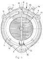
- Fig. 1
- in Draufsicht einen erfindungsgemäßen Lautsprecherhalter mit eingebautem Lautsprecher,
- Fig. 2
- einen Schnitt längs der Linie II-II in Fig. 1,
- Fig. 3
- in perspektivischer Darstellung den erfindungsgemäßen Lautsprecherhalter gemäß Fig. 1 mit eingebautem Lautsprecher,
- Fig. 4
- eine Unteransicht des erfindungsgemäßen Lautsprecherhalters.
Claims (12)
- Halter für einen Lautsprecher zum Einbau in Kraftfahrzeuge, dadurch gekennzeichnet, daß der Halter eine Aufnahme (2) für den Lautsprecher (1) aufweist, die mit wenigstens einer Auflage (7) versehen ist, mit der die Aufnahme (2) auf einem kraftfahrzeugseitigen Teil (11) aufliegt und auf der wenigstens eine Dichtung (34) angeordnet ist, die den Einbauraum des Lautsprechers (1) abdichtet.
- Halter nach Anspruch 1,
dadurch gekennzeichnet, daß die Aufnahme (2) korbförmig ausgebildet ist. - Halter nach Anspruch 1 oder 2,
dadurch gekennzeichnet, daß die Auflage (7) ein umlaufender, vorzugsweise radial abstehender Rand der Aufnahme (2) ist. - Halter nach einem der Ansprüche 1 bis 3,
dadurch gekennzeichnet, daß die Dichtung (34) als Dichtring ausgebildet ist, der über den Umfang der Aufnahme (2) verläuft. - Halter nach einem der Ansprüche 1 bis 4,
dadurch gekennzeichnet, daß die Dichtung (34) mit einem Ringteil (35) auf der Auflage (7) aufliegt. - Halter nach einem der Ansprüche 1 bis 5,
dadurch gekennzeichnet, daß die Dichtung (34) mit einer Dichtlippe (37) versehen ist, die unter elastischer Verformung an einer Seitenwand (38) des Einbauraumes anliegt. - Halter nach einem der Ansprüche 1 bis 6,
dadurch gekennzeichnet, daß der Halter aus einem harten Kunststoff besteht, wie Polykarbonat mit Glasfasern, Polypropylen, Polyacryl oder Acrylnitril-Butadien-Styrol-Copolymere. - Halter nach einem der Ansprüche 1 bis 7,
dadurch gekennzeichnet, daß die Dichtung (34) aus weichem Kunststoff besteht. - Halter nach einem der Ansprüche 6 bis 8,
dadurch gekennzeichnet, daß die Dichtlippe (37) radial über die Auflage (7) ragt. - Verfahren zur Herstellung eines Halters nach einem der Ansprüche 1 bis 9,
dadurch gekennzeichnet, daß die Aufnahme (2) in einem ersten Schritt in einer Spritzgußmaschine gespritzt wird, und daß anschließend in einem zweiten Schritt die Dichtung (34) an die Aufnahme (2) angespritzt wird. - Verfahren nach Anspruch 10,
dadurch gekennzeichnet, daß die Aufnahme (2) nach dem ersten Spritzvorgang einer ersten Kavität der Spritzgußmaschine entnommen und zum Anspritzen der Dichtung (34) in eine zweite Kavität eingebracht wird. - Verfahren nach Anspruch 10,
dadurch gekennzeichnet, daß nach dem Spritzen der Aufnahme (2) die Kavität der Spritzgußmaschine zum Anspritzen der Dichtung (34) vergrößert wird.
Applications Claiming Priority (2)
| Application Number | Priority Date | Filing Date | Title |
|---|---|---|---|
| DE19957938A DE19957938A1 (de) | 1999-12-01 | 1999-12-01 | Halter für einen Lautsprecher zum Einbau in Kraftfahrzeuge sowie Verfahren zu dessen Herstellung |
| DE19957938 | 1999-12-01 |
Publications (4)
| Publication Number | Publication Date |
|---|---|
| EP1106438A2 true EP1106438A2 (de) | 2001-06-13 |
| EP1106438A3 EP1106438A3 (de) | 2003-10-22 |
| EP1106438B1 EP1106438B1 (de) | 2006-09-06 |
| EP1106438B2 EP1106438B2 (de) | 2010-06-09 |
Family
ID=7931067
Family Applications (1)
| Application Number | Title | Priority Date | Filing Date |
|---|---|---|---|
| EP00125563A Expired - Lifetime EP1106438B2 (de) | 1999-12-01 | 2000-11-22 | Anordnung eines Halters für einen Lautsprecher in einem Kraftfahrzeug |
Country Status (3)
| Country | Link |
|---|---|
| US (1) | US6457547B2 (de) |
| EP (1) | EP1106438B2 (de) |
| DE (2) | DE19957938A1 (de) |
Cited By (2)
| Publication number | Priority date | Publication date | Assignee | Title |
|---|---|---|---|---|
| GB2379577B (en) * | 2000-06-07 | 2004-07-28 | Honda Motor Co Ltd | Speaker Mounting Structure |
| US7876923B2 (en) | 2006-02-27 | 2011-01-25 | Finnegan Brendan J | Loudspeaker gasketing |
Families Citing this family (24)
| Publication number | Priority date | Publication date | Assignee | Title |
|---|---|---|---|---|
| DE19925944C2 (de) * | 1999-06-08 | 2001-11-29 | Harman Audio Electronic Sys | Lautsprecher mit einem frontseitig aufgesetzten Dichtelement und Verfahren zur Herstellung eines solchen Lautsprechers |
| JP2003063316A (ja) * | 2001-08-23 | 2003-03-05 | Sony Corp | 車両ドア用スピーカ装置 |
| DE10144665B4 (de) * | 2001-09-11 | 2007-05-03 | Brose Fahrzeugteile Gmbh & Co. Kg | Kraftfahrzeugtür mit einer mindestens einen Lautsprecher tragenden Wandung |
| US6756004B2 (en) | 2002-04-24 | 2004-06-29 | Lear Corporation | Method for manufacturing cockpit-type instrument panels |
| US20040159490A1 (en) * | 2003-02-03 | 2004-08-19 | Marlin Bruce E. | Compact loudspeaker and control switch assembly and method for installing and adjusting a loudspeaker in a partition |
| US7274797B2 (en) | 2003-07-14 | 2007-09-25 | Harman International Industries, Incorporated | Speaker housing |
| JP4603829B2 (ja) * | 2003-07-31 | 2010-12-22 | テーダブリュ電気株式会社 | スピーカの取付構造及びスピーカ |
| USD522498S1 (en) * | 2004-08-17 | 2006-06-06 | Matsushita Electric Industrial Co., Ltd. | Speaker |
| DE202004019006U1 (de) * | 2004-12-07 | 2006-04-20 | Brose Fahrzeugteile Gmbh & Co. Kommanditgesellschaft, Coburg | Lautsprecheranordnung in einer Kraftfahrzeugtür sowie Kraftfahrzeugtür |
| JP4718927B2 (ja) * | 2005-07-29 | 2011-07-06 | パイオニア株式会社 | スピーカ装置 |
| JP2007311967A (ja) * | 2006-05-17 | 2007-11-29 | Pioneer Electronic Corp | スピーカー装置 |
| US7628249B2 (en) * | 2007-06-07 | 2009-12-08 | Chrysler Group Llc | Automotive speaker enclosure |
| TWI387360B (zh) * | 2008-12-26 | 2013-02-21 | Acer Inc | 揚聲器 |
| US8462126B2 (en) * | 2009-07-20 | 2013-06-11 | Motorola Mobility Llc | Method for implementing zoom functionality on a portable device with opposing touch sensitive surfaces |
| US8497884B2 (en) | 2009-07-20 | 2013-07-30 | Motorola Mobility Llc | Electronic device and method for manipulating graphic user interface elements |
| FR2955225B1 (fr) * | 2010-01-14 | 2012-06-01 | Peugeot Citroen Automobiles Sa | Dispositif de support d'un haut-parleur, notamment sur un element de carrosserie d'un vehicule automobile |
| US8638975B2 (en) | 2011-08-17 | 2014-01-28 | Bose Corporation | Wiper seal for passive radiator |
| DE102011120982A1 (de) * | 2011-12-13 | 2013-06-13 | Volkswagen Aktiengesellschaft | Einbauteil mit Lautsprecheröffnung für eine Fahrzeugtür |
| CN202652457U (zh) * | 2012-04-27 | 2013-01-02 | 上海添帛国际贸易有限公司 | 同轴汽车扬声器整体式快装盆架 |
| US9081542B2 (en) | 2012-08-28 | 2015-07-14 | Google Technology Holdings LLC | Systems and methods for a wearable touch-sensitive device |
| DE102012108838A1 (de) * | 2012-09-19 | 2014-05-28 | Cross Match Technologies Gmbh | Verfahren und Vorrichtung zur Aufnahme von Fingerabdrücken auf Basis von Fingerabdruckscannern in zuverlässig hoher Qualität |
| US20150139475A1 (en) * | 2013-11-20 | 2015-05-21 | Kai Shuai Industrial Co., Ltd. | Speaker decorative rim mounting structure |
| US10015575B2 (en) | 2016-09-08 | 2018-07-03 | Poly-Planar Group, Llc | Speaker assembly |
| DE102021202513A1 (de) * | 2021-03-15 | 2022-09-15 | Brose Fahrzeugteile Se & Co. Kommanditgesellschaft, Bamberg | Montageanordnung eines Lautsprechers in einem Kraftfahrzeug |
Family Cites Families (12)
| Publication number | Priority date | Publication date | Assignee | Title |
|---|---|---|---|---|
| US4572326A (en) * | 1979-12-20 | 1986-02-25 | General Motors Corporation | Motor vehicle loudspeaker installation |
| DE3424434A1 (de) * | 1984-07-03 | 1985-10-31 | Daimler-Benz Ag, 7000 Stuttgart | Halter fuer einen lautsprecher in kraftfahrzeugen |
| US4653607A (en) * | 1985-12-10 | 1987-03-31 | American Motors Corporation | Speaker seal |
| US4853966A (en) * | 1987-10-29 | 1989-08-01 | Skrzycki Gary E | Speaker mounting system |
| JPH01162990U (de) † | 1988-04-30 | 1989-11-14 | ||
| FR2633568B1 (fr) * | 1988-07-01 | 1991-11-22 | Harman Automotive Sa | Retroviseur a boitier et embase bi-matiere |
| DE4111748A1 (de) † | 1991-04-11 | 1992-10-15 | Nokia Deutschland Gmbh | Lautsprecher mit sicke und (einbauab-) dichtung vereinigenden bauteil |
| JP3080098B2 (ja) * | 1992-01-15 | 2000-08-21 | アーサー リーチ,パトリック | スピーカーのコーン・エッジ組立体を製造する方法及び装置 |
| US5532437A (en) * | 1995-06-06 | 1996-07-02 | Ford Motor Company | Speaker assembly |
| US5739481A (en) † | 1996-05-17 | 1998-04-14 | Lucent Technologies Inc. | Speaker mounting system |
| DE19752786A1 (de) * | 1996-12-19 | 1998-06-25 | Sarnatech Paulmann & Crone | Verfahren zur Herstellung von Ablagefächern |
| DE19925944C2 (de) † | 1999-06-08 | 2001-11-29 | Harman Audio Electronic Sys | Lautsprecher mit einem frontseitig aufgesetzten Dichtelement und Verfahren zur Herstellung eines solchen Lautsprechers |
-
1999
- 1999-12-01 DE DE19957938A patent/DE19957938A1/de not_active Ceased
-
2000
- 2000-11-22 DE DE50013428T patent/DE50013428D1/de not_active Expired - Lifetime
- 2000-11-22 EP EP00125563A patent/EP1106438B2/de not_active Expired - Lifetime
- 2000-12-01 US US09/728,254 patent/US6457547B2/en not_active Expired - Lifetime
Non-Patent Citations (1)
| Title |
|---|
| None |
Cited By (3)
| Publication number | Priority date | Publication date | Assignee | Title |
|---|---|---|---|---|
| GB2379577B (en) * | 2000-06-07 | 2004-07-28 | Honda Motor Co Ltd | Speaker Mounting Structure |
| US6987860B2 (en) | 2000-06-07 | 2006-01-17 | Honda Giken Kogyo Kabushiki Kaisha | Speaker installation structure |
| US7876923B2 (en) | 2006-02-27 | 2011-01-25 | Finnegan Brendan J | Loudspeaker gasketing |
Also Published As
| Publication number | Publication date |
|---|---|
| EP1106438B1 (de) | 2006-09-06 |
| EP1106438B2 (de) | 2010-06-09 |
| US20010002632A1 (en) | 2001-06-07 |
| US6457547B2 (en) | 2002-10-01 |
| DE50013428D1 (de) | 2006-10-19 |
| EP1106438A3 (de) | 2003-10-22 |
| DE19957938A1 (de) | 2001-06-07 |
Similar Documents
| Publication | Publication Date | Title |
|---|---|---|
| EP1106438B1 (de) | Halter für einen Lautsprecher zum Einbau in Kraftfahrzeuge sowie Verfahren zu dessen Herstellung | |
| DE69010612T2 (de) | Lautsprecher-Abdeckgitter. | |
| DE69500828T2 (de) | Vorrichtung zum Halten eines Sitzkissens | |
| DE4238889C2 (de) | Verfahren zur Herstellung eines Deckels eines öffnungsfähigen Fahrzeugdaches | |
| EP3292604B1 (de) | Verfahren zum herstellen einer wanddurchführung für mehrere kabel sowie anordnung | |
| DE60001560T2 (de) | Lautsprecherbefestigungsanordnung für fahrzeug-verkleidungsteil | |
| DE202016103494U1 (de) | Kabelwanddurchführung und Bausatz | |
| DE102020104489B4 (de) | Vorrichtung zur Befestigung eines Fahrzeugbauteils in und/oder an einem Fahrzeug | |
| DE102005036857A1 (de) | Umspritzte, abgedichtete Drahtdurchführung | |
| DE102012222550A1 (de) | Kabelfitting und kabelbaum | |
| DE102012007052A1 (de) | Verbinderabstützwerkzeug, Verdrahtungswerkzeug und Verdrahtung | |
| DE4300113A1 (en) | Fastener with clamp for support and car component joint - has retaining fixture on attachment, holding clamp to bracket during assembly. | |
| DE102004062309A1 (de) | Tiefgezogener Behälter und Verfahren zu dessen Herstellung | |
| DE10314862A1 (de) | Sensoranordnung einer Einparkhilfe | |
| DE102007053995A1 (de) | Verfahren zur Herstellung einer Instrumententafel eines Kraftfahrzeugs | |
| EP3473496B1 (de) | Haltevorrichtung und baugruppe mit einer haltevorrichtung | |
| DE102016010493A1 (de) | Kraftfahrzeugtürgriffanordnung mit abgedichtetem Elektronikbauraum | |
| DE102016010560A1 (de) | Kraftfahrzeugtürgriffanordnung mit Montageerleichterung | |
| DE102018101304A1 (de) | Montagestruktur für türrahmenformteil | |
| DE69529800T2 (de) | Schlüsselbartstruktur für Kraftfahrzeug | |
| EP2012395A2 (de) | Elektrischer Steckverbinder mit Stossfänger und/oder Kabeleinführungstülle aus elastischem Material | |
| DE7819567U1 (de) | Frontelement für eine Karosserie, insbesondere für ein Automobil | |
| DE10036429A1 (de) | Vorrichtung zum Befestigen einer Abschirmung an einem Motor | |
| DE102008011697A1 (de) | Airbaganordnung für ein Fahrzeug | |
| DE3641584A1 (de) | Lautsprecherdichtung |
Legal Events
| Date | Code | Title | Description |
|---|---|---|---|
| PUAI | Public reference made under article 153(3) epc to a published international application that has entered the european phase |
Free format text: ORIGINAL CODE: 0009012 |
|
| AK | Designated contracting states |
Kind code of ref document: A2 Designated state(s): AT BE CH CY DE DK ES FI FR GB GR IE IT LI LU MC NL PT SE TR |
|
| AX | Request for extension of the european patent |
Free format text: AL;LT;LV;MK;RO;SI |
|
| RIC1 | Information provided on ipc code assigned before grant |
Ipc: 7B 29C 45/00 B Ipc: 7B 60R 11/02 A Ipc: 7H 04R 1/02 B |
|
| PUAL | Search report despatched |
Free format text: ORIGINAL CODE: 0009013 |
|
| AK | Designated contracting states |
Kind code of ref document: A3 Designated state(s): AT BE CH CY DE DK ES FI FR GB GR IE IT LI LU MC NL PT SE TR |
|
| AX | Request for extension of the european patent |
Extension state: AL LT LV MK RO SI |
|
| RIC1 | Information provided on ipc code assigned before grant |
Ipc: 7B 29C 45/00 B Ipc: 7B 60R 11/02 A Ipc: 7H 04R 1/02 B Ipc: 7B 29C 45/16 B |
|
| 17P | Request for examination filed |
Effective date: 20040316 |
|
| 17Q | First examination report despatched |
Effective date: 20040527 |
|
| AKX | Designation fees paid |
Designated state(s): DE FR GB IE IT SE |
|
| GRAP | Despatch of communication of intention to grant a patent |
Free format text: ORIGINAL CODE: EPIDOSNIGR1 |
|
| GRAS | Grant fee paid |
Free format text: ORIGINAL CODE: EPIDOSNIGR3 |
|
| RAP1 | Party data changed (applicant data changed or rights of an application transferred) |
Owner name: SCHEFENACKER VISION SYSTEMS GERMANY GMBH |
|
| GRAA | (expected) grant |
Free format text: ORIGINAL CODE: 0009210 |
|
| AK | Designated contracting states |
Kind code of ref document: B1 Designated state(s): DE FR GB IE IT SE |
|
| PG25 | Lapsed in a contracting state [announced via postgrant information from national office to epo] |
Ref country code: IT Free format text: LAPSE BECAUSE OF FAILURE TO SUBMIT A TRANSLATION OF THE DESCRIPTION OR TO PAY THE FEE WITHIN THE PRESCRIBED TIME-LIMIT;WARNING: LAPSES OF ITALIAN PATENTS WITH EFFECTIVE DATE BEFORE 2007 MAY HAVE OCCURRED AT ANY TIME BEFORE 2007. THE CORRECT EFFECTIVE DATE MAY BE DIFFERENT FROM THE ONE RECORDED. Effective date: 20060906 |
|
| REG | Reference to a national code |
Ref country code: GB Ref legal event code: FG4D Free format text: NOT ENGLISH |
|
| REG | Reference to a national code |
Ref country code: IE Ref legal event code: FG4D Free format text: LANGUAGE OF EP DOCUMENT: GERMAN |
|
| REF | Corresponds to: |
Ref document number: 50013428 Country of ref document: DE Date of ref document: 20061019 Kind code of ref document: P |
|
| GBT | Gb: translation of ep patent filed (gb section 77(6)(a)/1977) |
Effective date: 20061121 |
|
| REG | Reference to a national code |
Ref country code: SE Ref legal event code: TRGR |
|
| ET | Fr: translation filed | ||
| PLBI | Opposition filed |
Free format text: ORIGINAL CODE: 0009260 |
|
| PLAX | Notice of opposition and request to file observation + time limit sent |
Free format text: ORIGINAL CODE: EPIDOSNOBS2 |
|
| 26 | Opposition filed |
Opponent name: GEALAN FORMTEILE GMBH Effective date: 20070606 |
|
| PLBP | Opposition withdrawn |
Free format text: ORIGINAL CODE: 0009264 |
|
| PLAY | Examination report in opposition despatched + time limit |
Free format text: ORIGINAL CODE: EPIDOSNORE2 |
|
| PLAH | Information related to despatch of examination report in opposition + time limit modified |
Free format text: ORIGINAL CODE: EPIDOSCORE2 |
|
| PGFP | Annual fee paid to national office [announced via postgrant information from national office to epo] |
Ref country code: IE Payment date: 20081124 Year of fee payment: 9 |
|
| PLBC | Reply to examination report in opposition received |
Free format text: ORIGINAL CODE: EPIDOSNORE3 |
|
| PGFP | Annual fee paid to national office [announced via postgrant information from national office to epo] |
Ref country code: IT Payment date: 20081122 Year of fee payment: 9 Ref country code: SE Payment date: 20081114 Year of fee payment: 9 |
|
| RTI2 | Title (correction) |
Free format text: ARRANGEMENT OF A SUPPORT FOR A LOUDSPEAKER MOUNTED IN A VEHICLE |
|
| PUAH | Patent maintained in amended form |
Free format text: ORIGINAL CODE: 0009272 |
|
| STAA | Information on the status of an ep patent application or granted ep patent |
Free format text: STATUS: PATENT MAINTAINED AS AMENDED |
|
| 27A | Patent maintained in amended form |
Effective date: 20100609 |
|
| AK | Designated contracting states |
Kind code of ref document: B2 Designated state(s): DE FR GB IE IT SE |
|
| EUG | Se: european patent has lapsed | ||
| PG25 | Lapsed in a contracting state [announced via postgrant information from national office to epo] |
Ref country code: IE Free format text: LAPSE BECAUSE OF NON-PAYMENT OF DUE FEES Effective date: 20091123 |
|
| PG25 | Lapsed in a contracting state [announced via postgrant information from national office to epo] |
Ref country code: IT Free format text: LAPSE BECAUSE OF NON-PAYMENT OF DUE FEES Effective date: 20091122 |
|
| PG25 | Lapsed in a contracting state [announced via postgrant information from national office to epo] |
Ref country code: SE Free format text: LAPSE BECAUSE OF NON-PAYMENT OF DUE FEES Effective date: 20091123 |
|
| REG | Reference to a national code |
Ref country code: FR Ref legal event code: PLFP Year of fee payment: 16 |
|
| REG | Reference to a national code |
Ref country code: FR Ref legal event code: PLFP Year of fee payment: 17 |
|
| REG | Reference to a national code |
Ref country code: FR Ref legal event code: PLFP Year of fee payment: 18 |
|
| PGFP | Annual fee paid to national office [announced via postgrant information from national office to epo] |
Ref country code: DE Payment date: 20191121 Year of fee payment: 20 |
|
| PGFP | Annual fee paid to national office [announced via postgrant information from national office to epo] |
Ref country code: FR Payment date: 20191120 Year of fee payment: 20 |
|
| PGFP | Annual fee paid to national office [announced via postgrant information from national office to epo] |
Ref country code: GB Payment date: 20191120 Year of fee payment: 20 |
|
| REG | Reference to a national code |
Ref country code: DE Ref legal event code: R071 Ref document number: 50013428 Country of ref document: DE |
|
| REG | Reference to a national code |
Ref country code: GB Ref legal event code: PE20 Expiry date: 20201121 |
|
| PG25 | Lapsed in a contracting state [announced via postgrant information from national office to epo] |
Ref country code: GB Free format text: LAPSE BECAUSE OF EXPIRATION OF PROTECTION Effective date: 20201121 |