EP1106463B1 - Vorrichtung zur Dosierung der Fahrzeugverzögerung - Google Patents
Vorrichtung zur Dosierung der Fahrzeugverzögerung Download PDFInfo
- Publication number
- EP1106463B1 EP1106463B1 EP00420244A EP00420244A EP1106463B1 EP 1106463 B1 EP1106463 B1 EP 1106463B1 EP 00420244 A EP00420244 A EP 00420244A EP 00420244 A EP00420244 A EP 00420244A EP 1106463 B1 EP1106463 B1 EP 1106463B1
- Authority
- EP
- European Patent Office
- Prior art keywords
- vehicle
- piston
- cylinder
- lever
- deceleration
- Prior art date
- Legal status (The legal status is an assumption and is not a legal conclusion. Google has not performed a legal analysis and makes no representation as to the accuracy of the status listed.)
- Expired - Lifetime
Links
- 238000006243 chemical reaction Methods 0.000 description 4
- 238000000034 method Methods 0.000 description 3
- 230000001133 acceleration Effects 0.000 description 2
- 230000009471 action Effects 0.000 description 2
- 238000006073 displacement reaction Methods 0.000 description 2
- 238000012360 testing method Methods 0.000 description 2
- 238000013459 approach Methods 0.000 description 1
- 230000008878 coupling Effects 0.000 description 1
- 238000010168 coupling process Methods 0.000 description 1
- 238000005859 coupling reaction Methods 0.000 description 1
- 238000013461 design Methods 0.000 description 1
- 239000012530 fluid Substances 0.000 description 1
- 230000006872 improvement Effects 0.000 description 1
- 238000005259 measurement Methods 0.000 description 1
- 238000005086 pumping Methods 0.000 description 1
- 230000004044 response Effects 0.000 description 1
- 230000035807 sensation Effects 0.000 description 1
- 239000000725 suspension Substances 0.000 description 1
Images



Classifications
-
- B—PERFORMING OPERATIONS; TRANSPORTING
- B60—VEHICLES IN GENERAL
- B60T—VEHICLE BRAKE CONTROL SYSTEMS OR PARTS THEREOF; BRAKE CONTROL SYSTEMS OR PARTS THEREOF, IN GENERAL; ARRANGEMENT OF BRAKING ELEMENTS ON VEHICLES IN GENERAL; PORTABLE DEVICES FOR PREVENTING UNWANTED MOVEMENT OF VEHICLES; VEHICLE MODIFICATIONS TO FACILITATE COOLING OF BRAKES
- B60T11/00—Transmitting braking action from initiating means to ultimate brake actuator without power assistance or drive or where such assistance or drive is irrelevant
- B60T11/10—Transmitting braking action from initiating means to ultimate brake actuator without power assistance or drive or where such assistance or drive is irrelevant transmitting by fluid means, e.g. hydraulic
- B60T11/16—Master control, e.g. master cylinders
-
- B—PERFORMING OPERATIONS; TRANSPORTING
- B60—VEHICLES IN GENERAL
- B60T—VEHICLE BRAKE CONTROL SYSTEMS OR PARTS THEREOF; BRAKE CONTROL SYSTEMS OR PARTS THEREOF, IN GENERAL; ARRANGEMENT OF BRAKING ELEMENTS ON VEHICLES IN GENERAL; PORTABLE DEVICES FOR PREVENTING UNWANTED MOVEMENT OF VEHICLES; VEHICLE MODIFICATIONS TO FACILITATE COOLING OF BRAKES
- B60T7/00—Brake-action initiating means
- B60T7/02—Brake-action initiating means for personal initiation
- B60T7/04—Brake-action initiating means for personal initiation foot actuated
- B60T7/06—Disposition of pedal
-
- B—PERFORMING OPERATIONS; TRANSPORTING
- B62—LAND VEHICLES FOR TRAVELLING OTHERWISE THAN ON RAILS
- B62L—BRAKES SPECIALLY ADAPTED FOR CYCLES
- B62L3/00—Brake-actuating mechanisms; Arrangements thereof
- B62L3/02—Brake-actuating mechanisms; Arrangements thereof for control by a hand lever
- B62L3/023—Brake-actuating mechanisms; Arrangements thereof for control by a hand lever acting on fluid pressure systems
Definitions
- the invention relates to the technical sector of braking devices for all types of vehicles, such as cars, motorcycles, airplanes ...
- One of the essential parts of a braking device is constituted by the master cylinder hydraulically connected to the braking members as such, disks or drums and coupled to one or more actuator members, operable by hand or feet, in depending on the type of vehicle considered.
- the brake master cylinder comprises a cylinder hydraulically connected to the brake circuit and coupled to a portion of the vehicle.
- the cylinder receives a piston coupled to the actuator member, itself actuated on a part of the vehicle.
- the purpose of the braking action is to create a deceleration of the vehicle followed or not by the total stopping of the latter.
- This dosage results essentially from the displacement of the force on the actuator member of braking (lever or pedal). This results in a reaction which is the value of the deceleration that can be felt in different ways by the driver. In reality, this value of the deceleration is very difficult to assess.
- this value of the deceleration can be perceived directly by a sensation of the phenomenon of horizontal acceleration in the body of the user, or directly by integrating the decrease of the speed perceived by the scrolling of the landscape or even, indirectly, by appreciating the attitude variation of the considered vehicle due to the horizontal component of acceleration, the vehicle having a tendency to plunge forward.
- This reaction is the most used for the determination of the brakes, but is tainted with errors. Indeed, at equal deceleration, the vehicle dive, varies according to its loading, the suspension setting and other phenomena.
- the driver acts on the braking member causing a reaction of his vehicle.
- the driver is obliged to modify several times the action exerted on the braking member to obtain the desired deceleration.
- the result obtained is not immediate. This response time is, therefore, likely to lose many meters over a stopping distance.
- the pilot determines, by learning, the precise effort it must apply to the actuator member, to achieve the desired deceleration. In this case, the result is instantaneous, but the command string must be faithful. Otherwise, the result will not be that expected by the driver.
- the driver will learn to use his braking system or to experimentally determine the necessary stroke and force on the braking actuator member to achieve the desired deceleration. This learning is done naturally and unconsciously.
- the ideal braking is therefore to have a perfectly linear connection between the stroke of the actuator member and the deceleration and between the force exerted on the actuator member and the deceleration.
- the precision of the braking dosage is largely degraded by the appearance of numerous friction, in particular at the level of the joints, joints on plain bearings, pistons in the bore of the cylinder ...
- FIGS. 1 and 2 show the hysteresis curve resulting from the measurements carried out on a test bench and corresponding to master cylinders of conventional design, mounted on motorcycles of large displacements.
- Figure 1 corresponds to a radial master cylinder
- Figure 2 corresponds to axial master cylinder
- the offset at the start of the race corresponds to a return spring of the piston of the master cylinder, necessary to combat the friction back.
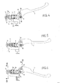
- the master cylinder comprises a cylinder (1) inside which is mounted coaxially a piston (2).
- the cylinder (1) is connected by any known and appropriate means to the hydraulic circuit of the brake system as such.
- the piston (2) has grooves (2a) and (2b) or other arrangements capable of receiving seals (3). Any return spring or other piston (2) is not shown.
- a device has been devised to measure the deceleration during a force applied to an actuator member (7) of a master cylinder, according to which the end (1a) of the cylinder (1), located opposite the other end from which the piston (2) overflows, is oscillatingly articulated on a part of the vehicle such as a housing (4) or other, depending the type of vehicle considered.
- the oscillating mounting of the cylinder (1) relative to the support member (4) is effected by means of an axis (5) mounted in combination with a bearing (6).
- the end (1a) constitutes a rounded nose mounted between the two wings of a yoke that has a portion of the support member (4).
- the entire axis (5) with its bearing (6) is mounted transversely to ensure the oscillating coupling of said nose (1a) in the yoke of said support member (4).
- the rod (2c) of the piston (2) is hingedly coupled to a suitable part of an actuator member (7), which may be constituted by a lever, in the case of a motorcycle ( Figures 4, 5 and 6) or by a pedal, in the case of a motor vehicle ( Figure 7).
- the articulated mounting of the piston (2) relative to the actuator member (7) is effected by means of an axis (8) in combination with a bearing (9). ).
- the actuator member (7) is, in turn, actuated on a fixed part of the vehicle in question, by means of an axis (10), in combination with a bearing (11).
- the articulated mounting of the piston (2) relative to the actuator member (7) and the actuator member (7) relative to the vehicle part can be performed in the same way as for the cylinder (1) , by arrangements in the form of a screed.
- these vibrations are dampened by the sliding movement of the piston, whereas such vibrations are directly transmitted at the lever, taking into account the characteristics according to the invention.
- the driver can feel instantly and precisely, the effectiveness of the brakes and also feel when the disc - pads friction is disrupted.
- control of the cylinder master of the lever can be effected by means of a rocker likely to have a lever distance adjustment system, in order to adapt the master cylinder at each size of the hand.
Landscapes
- Engineering & Computer Science (AREA)
- Mechanical Engineering (AREA)
- Transportation (AREA)
- Physics & Mathematics (AREA)
- Fluid Mechanics (AREA)
- Regulating Braking Force (AREA)
- Transmission Of Braking Force In Braking Systems (AREA)
- Braking Arrangements (AREA)
- Mechanical Control Devices (AREA)
- Motorcycle And Bicycle Frame (AREA)
- Control Of Transmission Device (AREA)
Claims (1)
- Vorrichtung zur Dosierung der Fahrzeugverzögerung, während eine Kraft auf ein Betätigungselement eines Hauptbremszylinders ausgeübt wird, die folgendes aufweist :- einen Zylinder (1), der mit dem Bremskreis hydraulisch verbunden und an einen Teil des Fahrzeuges angeschlossen ist;- der Zylinder (1) nimmt einen Kolben (2) auf, dessen Stange (2c) mit einem Hebel oder einem Pedal (7) verbunden ist, der bzw. das wiederum an einem Teil des Fahrzeuges angelenkt ist ; wobei- das Ende (1a) des Zylinders (1), das gegenüber dem anderen Ende angeordnet ist, von dem aus der Kolben (2) vorsteht, mit Hilfe einer ersten Achse (5) oszillierend an einem Teil (4) des Fahrzeuges angelenkt ist ;- die Stange (2c) des Kolbens (2) ist mit Hilfe einer zweiten Achse (8) gelenkig mit dem Betätigungselement (7) verbunden, wobei das Betätigungselement (7) mit Hilfe einer dritten Achse (10) an dem Teil des Fahrzeuges angelenkt ist, dadurch gekennzeichnet, dass die erste, zweite und dritte Achse (5, 8,10) jeweils in Verbindung mit einer Rolle (6, 9,11) montiert sind.
Applications Claiming Priority (2)
| Application Number | Priority Date | Filing Date | Title |
|---|---|---|---|
| FR9915706A FR2801856B1 (fr) | 1999-12-06 | 1999-12-06 | Maitre cylindre de freins pour vehicules |
| FR9915706 | 1999-12-06 |
Publications (2)
| Publication Number | Publication Date |
|---|---|
| EP1106463A1 EP1106463A1 (de) | 2001-06-13 |
| EP1106463B1 true EP1106463B1 (de) | 2007-07-11 |
Family
ID=9553198
Family Applications (1)
| Application Number | Title | Priority Date | Filing Date |
|---|---|---|---|
| EP00420244A Expired - Lifetime EP1106463B1 (de) | 1999-12-06 | 2000-11-27 | Vorrichtung zur Dosierung der Fahrzeugverzögerung |
Country Status (5)
| Country | Link |
|---|---|
| EP (1) | EP1106463B1 (de) |
| AT (1) | ATE366686T1 (de) |
| DE (1) | DE60035472T2 (de) |
| ES (1) | ES2290006T3 (de) |
| FR (1) | FR2801856B1 (de) |
Families Citing this family (4)
| Publication number | Priority date | Publication date | Assignee | Title |
|---|---|---|---|---|
| GB2407147A (en) * | 2003-10-15 | 2005-04-20 | Caithness Dev Ltd | Drive-by-wire pedal with hysteresis device |
| FR2977918B1 (fr) * | 2011-07-13 | 2014-03-28 | 6Tm | Systeme de commande hydraulique |
| US10829180B2 (en) * | 2017-08-28 | 2020-11-10 | Shimano Inc. | Hydraulic operating device |
| CN111017099A (zh) * | 2019-12-19 | 2020-04-17 | 重庆科朗机动车制动器有限公司 | 一种液压制动器可调节跨距手柄 |
Family Cites Families (3)
| Publication number | Priority date | Publication date | Assignee | Title |
|---|---|---|---|---|
| JPH041034Y2 (de) * | 1989-09-13 | 1992-01-14 | Nissin Kogyo Kk | |
| DE9315502U1 (de) * | 1993-10-13 | 1993-12-09 | INA Wälzlager Schaeffler KG, 91074 Herzogenaurach | Pedal- und Geberzylindergestaltung |
| DE4406384C2 (de) * | 1994-02-26 | 1995-12-14 | Deere & Co | Bremseinrichtung und Ausgleichsrolle |
-
1999
- 1999-12-06 FR FR9915706A patent/FR2801856B1/fr not_active Expired - Lifetime
-
2000
- 2000-11-27 ES ES00420244T patent/ES2290006T3/es not_active Expired - Lifetime
- 2000-11-27 EP EP00420244A patent/EP1106463B1/de not_active Expired - Lifetime
- 2000-11-27 AT AT00420244T patent/ATE366686T1/de not_active IP Right Cessation
- 2000-11-27 DE DE60035472T patent/DE60035472T2/de not_active Expired - Lifetime
Non-Patent Citations (1)
| Title |
|---|
| None * |
Also Published As
| Publication number | Publication date |
|---|---|
| ATE366686T1 (de) | 2007-08-15 |
| EP1106463A1 (de) | 2001-06-13 |
| FR2801856B1 (fr) | 2002-01-25 |
| DE60035472D1 (de) | 2007-08-23 |
| ES2290006T3 (es) | 2008-02-16 |
| DE60035472T2 (de) | 2008-04-17 |
| FR2801856A1 (fr) | 2001-06-08 |
Similar Documents
| Publication | Publication Date | Title |
|---|---|---|
| US5050381A (en) | Master cylinder with adjustable leverage | |
| EP0283328B1 (de) | Lastabhängiges Fahrzeugbremsventil | |
| US12005992B2 (en) | Hydraulic operating device for human-powered vehicle | |
| JP5300060B2 (ja) | 制動装置 | |
| WO2005047722A1 (fr) | Système de commande hydraulique d'un embrayage comportant des moyens d'assistance interposés entre l'émetteur et le récepteur du système. | |
| FR2641503A1 (fr) | Suspension a carrossage variable pour vehicule automobile | |
| EP1600347B1 (de) | Bremspedalsimulator, Hauptbremszylinder für ein Fahrzeug und Verfahren zur dessen Steuerung | |
| US4842102A (en) | Disc brake for wheeled vehicle or the like | |
| FR2574958A1 (fr) | Timonnerie mecanique admettant une commande prioritaire notamment pour la commande des gaz dans une automobile | |
| FR2809177A1 (fr) | Detecteur d'effort de pedalage ou de tension de chaine et dispositifs utilisant ledit detecteur | |
| EP1106463A1 (de) | Vorrichtung zur Dosierung der Fahrzeugverzögerung | |
| WO2002000483A1 (fr) | Dispositif de freinage d'un vehicule | |
| FR2533524A1 (fr) | Dispositif anti-soulevement pour vehicule automobile a deux roues | |
| JPS61241287A (ja) | 車両の制動レバ−位置調整装置 | |
| GB2077871A (en) | Motor cycle braking systems | |
| GB2456664A (en) | Master cylinder having an operating lever of which the mechanical advantage may be adjusted | |
| TWI870366B (zh) | 操作裝置 | |
| FR2593450A1 (fr) | Systeme de freinage a regulation du glissement. | |
| JP2002287837A (ja) | ペダル装置 | |
| EP1269036B1 (de) | Bremssattel mit mindestens zwei sich gegenüberliegenden kolben | |
| EP0256897A1 (de) | Hilfseinrichtung für die Bedienung einer Niveauregelung für Kraftfahrzeuge | |
| JP2026008593A (ja) | 鞍乗型車両 | |
| EP0915790B1 (de) | Hilfskraftunterstütztes bremssystem mit geregelter reaktion | |
| JPH05105054A (ja) | アンチロツクブレーキ装置 | |
| BE1010284A7 (fr) | Voiture ecole et son utilisation. |
Legal Events
| Date | Code | Title | Description |
|---|---|---|---|
| PUAI | Public reference made under article 153(3) epc to a published international application that has entered the european phase |
Free format text: ORIGINAL CODE: 0009012 |
|
| AK | Designated contracting states |
Kind code of ref document: A1 Designated state(s): AT BE CH CY DE DK ES FI FR GB GR IE IT LI LU MC NL PT SE TR |
|
| AX | Request for extension of the european patent |
Free format text: AL;LT;LV;MK;RO;SI |
|
| 17P | Request for examination filed |
Effective date: 20011112 |
|
| AKX | Designation fees paid |
Free format text: AT BE CH CY DE DK ES FI FR GB GR IE IT LI LU MC NL PT SE TR |
|
| 17Q | First examination report despatched |
Effective date: 20050602 |
|
| GRAP | Despatch of communication of intention to grant a patent |
Free format text: ORIGINAL CODE: EPIDOSNIGR1 |
|
| GRAS | Grant fee paid |
Free format text: ORIGINAL CODE: EPIDOSNIGR3 |
|
| GRAA | (expected) grant |
Free format text: ORIGINAL CODE: 0009210 |
|
| AK | Designated contracting states |
Kind code of ref document: B1 Designated state(s): AT BE CH CY DE DK ES FI FR GB GR IE IT LI LU MC NL PT SE TR |
|
| REG | Reference to a national code |
Ref country code: GB Ref legal event code: FG4D Free format text: NOT ENGLISH |
|
| REG | Reference to a national code |
Ref country code: CH Ref legal event code: EP |
|
| REF | Corresponds to: |
Ref document number: 60035472 Country of ref document: DE Date of ref document: 20070823 Kind code of ref document: P |
|
| REG | Reference to a national code |
Ref country code: IE Ref legal event code: FG4D Free format text: LANGUAGE OF EP DOCUMENT: FRENCH |
|
| GBT | Gb: translation of ep patent filed (gb section 77(6)(a)/1977) |
Effective date: 20071015 |
|
| PG25 | Lapsed in a contracting state [announced via postgrant information from national office to epo] |
Ref country code: FI Free format text: LAPSE BECAUSE OF FAILURE TO SUBMIT A TRANSLATION OF THE DESCRIPTION OR TO PAY THE FEE WITHIN THE PRESCRIBED TIME-LIMIT Effective date: 20070711 Ref country code: NL Free format text: LAPSE BECAUSE OF FAILURE TO SUBMIT A TRANSLATION OF THE DESCRIPTION OR TO PAY THE FEE WITHIN THE PRESCRIBED TIME-LIMIT Effective date: 20070711 Ref country code: PT Free format text: LAPSE BECAUSE OF FAILURE TO SUBMIT A TRANSLATION OF THE DESCRIPTION OR TO PAY THE FEE WITHIN THE PRESCRIBED TIME-LIMIT Effective date: 20071211 |
|
| NLV1 | Nl: lapsed or annulled due to failure to fulfill the requirements of art. 29p and 29m of the patents act | ||
| REG | Reference to a national code |
Ref country code: ES Ref legal event code: FG2A Ref document number: 2290006 Country of ref document: ES Kind code of ref document: T3 |
|
| PG25 | Lapsed in a contracting state [announced via postgrant information from national office to epo] |
Ref country code: AT Free format text: LAPSE BECAUSE OF FAILURE TO SUBMIT A TRANSLATION OF THE DESCRIPTION OR TO PAY THE FEE WITHIN THE PRESCRIBED TIME-LIMIT Effective date: 20070711 |
|
| REG | Reference to a national code |
Ref country code: IE Ref legal event code: FD4D |
|
| PG25 | Lapsed in a contracting state [announced via postgrant information from national office to epo] |
Ref country code: GR Free format text: LAPSE BECAUSE OF FAILURE TO SUBMIT A TRANSLATION OF THE DESCRIPTION OR TO PAY THE FEE WITHIN THE PRESCRIBED TIME-LIMIT Effective date: 20071012 Ref country code: DK Free format text: LAPSE BECAUSE OF FAILURE TO SUBMIT A TRANSLATION OF THE DESCRIPTION OR TO PAY THE FEE WITHIN THE PRESCRIBED TIME-LIMIT Effective date: 20070711 |
|
| PLBE | No opposition filed within time limit |
Free format text: ORIGINAL CODE: 0009261 |
|
| STAA | Information on the status of an ep patent application or granted ep patent |
Free format text: STATUS: NO OPPOSITION FILED WITHIN TIME LIMIT |
|
| PG25 | Lapsed in a contracting state [announced via postgrant information from national office to epo] |
Ref country code: IE Free format text: LAPSE BECAUSE OF FAILURE TO SUBMIT A TRANSLATION OF THE DESCRIPTION OR TO PAY THE FEE WITHIN THE PRESCRIBED TIME-LIMIT Effective date: 20070711 |
|
| 26N | No opposition filed |
Effective date: 20080414 |
|
| PG25 | Lapsed in a contracting state [announced via postgrant information from national office to epo] |
Ref country code: MC Free format text: LAPSE BECAUSE OF NON-PAYMENT OF DUE FEES Effective date: 20071130 Ref country code: SE Free format text: LAPSE BECAUSE OF FAILURE TO SUBMIT A TRANSLATION OF THE DESCRIPTION OR TO PAY THE FEE WITHIN THE PRESCRIBED TIME-LIMIT Effective date: 20071011 |
|
| PG25 | Lapsed in a contracting state [announced via postgrant information from national office to epo] |
Ref country code: LI Free format text: LAPSE BECAUSE OF NON-PAYMENT OF DUE FEES Effective date: 20071130 Ref country code: CH Free format text: LAPSE BECAUSE OF NON-PAYMENT OF DUE FEES Effective date: 20071130 |
|
| REG | Reference to a national code |
Ref country code: CH Ref legal event code: PL |
|
| REG | Reference to a national code |
Ref country code: FR Ref legal event code: ST Effective date: 20080930 |
|
| PG25 | Lapsed in a contracting state [announced via postgrant information from national office to epo] |
Ref country code: FR Free format text: LAPSE BECAUSE OF NON-PAYMENT OF DUE FEES Effective date: 20071130 |
|
| PG25 | Lapsed in a contracting state [announced via postgrant information from national office to epo] |
Ref country code: CY Free format text: LAPSE BECAUSE OF FAILURE TO SUBMIT A TRANSLATION OF THE DESCRIPTION OR TO PAY THE FEE WITHIN THE PRESCRIBED TIME-LIMIT Effective date: 20070711 |
|
| PG25 | Lapsed in a contracting state [announced via postgrant information from national office to epo] |
Ref country code: LU Free format text: LAPSE BECAUSE OF NON-PAYMENT OF DUE FEES Effective date: 20071127 |
|
| PG25 | Lapsed in a contracting state [announced via postgrant information from national office to epo] |
Ref country code: TR Free format text: LAPSE BECAUSE OF FAILURE TO SUBMIT A TRANSLATION OF THE DESCRIPTION OR TO PAY THE FEE WITHIN THE PRESCRIBED TIME-LIMIT Effective date: 20070711 |
|
| PGFP | Annual fee paid to national office [announced via postgrant information from national office to epo] |
Ref country code: DE Payment date: 20191021 Year of fee payment: 20 |
|
| PGFP | Annual fee paid to national office [announced via postgrant information from national office to epo] |
Ref country code: BE Payment date: 20191024 Year of fee payment: 20 Ref country code: ES Payment date: 20191202 Year of fee payment: 20 Ref country code: IT Payment date: 20191021 Year of fee payment: 20 |
|
| PGFP | Annual fee paid to national office [announced via postgrant information from national office to epo] |
Ref country code: GB Payment date: 20191022 Year of fee payment: 20 |
|
| REG | Reference to a national code |
Ref country code: DE Ref legal event code: R071 Ref document number: 60035472 Country of ref document: DE |
|
| REG | Reference to a national code |
Ref country code: GB Ref legal event code: PE20 Expiry date: 20201126 |
|
| REG | Reference to a national code |
Ref country code: BE Ref legal event code: MK Effective date: 20201127 |
|
| PG25 | Lapsed in a contracting state [announced via postgrant information from national office to epo] |
Ref country code: GB Free format text: LAPSE BECAUSE OF EXPIRATION OF PROTECTION Effective date: 20201126 |
|
| REG | Reference to a national code |
Ref country code: ES Ref legal event code: FD2A Effective date: 20210806 |
|
| PG25 | Lapsed in a contracting state [announced via postgrant information from national office to epo] |
Ref country code: ES Free format text: LAPSE BECAUSE OF EXPIRATION OF PROTECTION Effective date: 20201128 |