EP1106472A2 - Dispositif pour transport de charges - Google Patents
Dispositif pour transport de charges Download PDFInfo
- Publication number
- EP1106472A2 EP1106472A2 EP00500218A EP00500218A EP1106472A2 EP 1106472 A2 EP1106472 A2 EP 1106472A2 EP 00500218 A EP00500218 A EP 00500218A EP 00500218 A EP00500218 A EP 00500218A EP 1106472 A2 EP1106472 A2 EP 1106472A2
- Authority
- EP
- European Patent Office
- Prior art keywords
- load
- wheels
- tractor
- seat
- support
- Prior art date
- Legal status (The legal status is an assumption and is not a legal conclusion. Google has not performed a legal analysis and makes no representation as to the accuracy of the status listed.)
- Granted
Links
- 230000005540 biological transmission Effects 0.000 claims description 8
- 238000005096 rolling process Methods 0.000 claims description 5
- 238000000605 extraction Methods 0.000 claims description 4
- 230000010355 oscillation Effects 0.000 claims description 2
- 239000012632 extractable Substances 0.000 claims 1
- 239000000463 material Substances 0.000 description 3
- 238000010276 construction Methods 0.000 description 2
- 230000001133 acceleration Effects 0.000 description 1
- 230000000295 complement effect Effects 0.000 description 1
- 239000000284 extract Substances 0.000 description 1
- 230000002349 favourable effect Effects 0.000 description 1
- 230000014759 maintenance of location Effects 0.000 description 1
- 230000004048 modification Effects 0.000 description 1
- 238000012986 modification Methods 0.000 description 1
- 230000000284 resting effect Effects 0.000 description 1
- 230000000717 retained effect Effects 0.000 description 1
Images

Classifications
-
- B—PERFORMING OPERATIONS; TRANSPORTING
- B62—LAND VEHICLES FOR TRAVELLING OTHERWISE THAN ON RAILS
- B62B—HAND-PROPELLED VEHICLES, e.g. HAND CARTS OR PERAMBULATORS; SLEDGES
- B62B3/00—Hand carts having more than one axis carrying transport wheels; Steering devices therefor; Equipment therefor
- B62B3/04—Hand carts having more than one axis carrying transport wheels; Steering devices therefor; Equipment therefor involving means for grappling or securing in place objects to be carried; Loading or unloading equipment
- B62B3/06—Hand carts having more than one axis carrying transport wheels; Steering devices therefor; Equipment therefor involving means for grappling or securing in place objects to be carried; Loading or unloading equipment for simply clearing the load from the ground
- B62B3/0612—Hand carts having more than one axis carrying transport wheels; Steering devices therefor; Equipment therefor involving means for grappling or securing in place objects to be carried; Loading or unloading equipment for simply clearing the load from the ground power operated
-
- B—PERFORMING OPERATIONS; TRANSPORTING
- B62—LAND VEHICLES FOR TRAVELLING OTHERWISE THAN ON RAILS
- B62D—MOTOR VEHICLES; TRAILERS
- B62D51/00—Motor vehicles characterised by the driver not being seated
- B62D51/04—Motor vehicles characterised by the driver not being seated the driver walking
- B62D51/06—Uniaxle walk-type tractors
-
- B—PERFORMING OPERATIONS; TRANSPORTING
- B62—LAND VEHICLES FOR TRAVELLING OTHERWISE THAN ON RAILS
- B62D—MOTOR VEHICLES; TRAILERS
- B62D53/00—Tractor-trailer combinations; Road trains
- B62D53/02—Tractor-trailer combinations; Road trains comprising a uniaxle tractor unit and a uniaxle trailer unit
-
- B—PERFORMING OPERATIONS; TRANSPORTING
- B62—LAND VEHICLES FOR TRAVELLING OTHERWISE THAN ON RAILS
- B62B—HAND-PROPELLED VEHICLES, e.g. HAND CARTS OR PERAMBULATORS; SLEDGES
- B62B2203/00—Grasping, holding, supporting the objects
- B62B2203/10—Grasping, holding, supporting the objects comprising lifting means
-
- B—PERFORMING OPERATIONS; TRANSPORTING
- B62—LAND VEHICLES FOR TRAVELLING OTHERWISE THAN ON RAILS
- B62B—HAND-PROPELLED VEHICLES, e.g. HAND CARTS OR PERAMBULATORS; SLEDGES
- B62B2207/00—Joining hand-propelled vehicles or sledges together
- B62B2207/04—Forklift trucks with wheeled pallets
Definitions
- the present invention as its own name indicates relates to a tractor element making it possible to move dead charges, i.e. elements without rolling means and which under normal conditions are displaced suspended or lifted by mechanical means, while that with this device it will move by rolling with the own rolling means included in it.
- Containers of materials or rubble from the construction, goods stacking pallets and other type of elements with similar characteristics can move only by being lifted by a vehicle equipped of a lifting system of these, needing a large maneuvering space and second possibility access of the vehicle in question to the location of the charge.
- a lifting system of these When picking up rubble containers the currently existing trucks carrying out the operations of up and down the container to the vehicle from the part posterior of it need some maneuvering space about 10 meters, this type of truck cannot pick up containers in covered spaces where the truck cannot not enter, nor in pedestrian or very narrow streets where the vehicle itself cannot access them or they are missing sufficient space for maneuverability.
- the vehicles load elevators placed on pallets are useful when employed in a store where the goods are stored by this means, but they lack operativity on the street because they are limited in their charge and which is more important in terms of visibility than the vehicle driver must have, reason why they don't cannot travel on public roads.
- the device of the present invention resolves so completely favorable this problem because it was specially designed to transport large loads (between 2 and 4 T), through difficult or very difficult places to access it, either by the narrowness (streets, courtyard, cellars or other places covered) or restricted vehicle areas (gardens, parks, pedestrian streets, etc.)
- This device is formed by a tractor means comprising a support structure for an engine and controls extended to the front area where it incorporates a seat, support of the load to be transported, which is framed by the drive wheels capable of supporting the weight of the charge.
- a tractor means comprising a support structure for an engine and controls extended to the front area where it incorporates a seat, support of the load to be transported, which is framed by the drive wheels capable of supporting the weight of the charge.
- the central area it has wheels mounted in extractable half-axes, remaining in the device while that this one moves free of charge, yielding them to this at some point to mount each of the wheels laterally at one end, while at the opposite end the load is mounted on said seat, located between the two drive wheels, thus keeping the tractor body high, in a substantially horizontal position, so that at this position it is possible to move the load while driving and by means of the motor included in this device, in the even driving through very difficult places to access it.
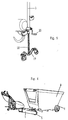
- Figure 6 shows a perspective view of this load transport device available transport a container (8) of the type used usually for transporting materials or rubble of construction.
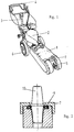
- the load transport device object of the present invention available to move as a autonomous means, incorporating two groups of wheels (5) and (6), of which the front group (5) is located in the extension presenting the structure of this tractor means (1) towards the front, presenting between this pair of wheels drive (5) a seat (7) constituting the fulcrum of the load to be transported.
- the front group (5) is located in the extension presenting the structure of this tractor means (1) towards the front, presenting between this pair of wheels drive (5) a seat (7) constituting the fulcrum of the load to be transported.
- On the rear part it presents a motor element (2) and at the rear a set of controls (4) for the maneuverability of the tractor under conditions of operation, acceleration, brake or steering.
- the seat (7) constituting the fulcrum by one of the ends of the load (8) is shown in more detail in Figure (2) and it includes an axial bearing (9) allowing the rotation of the support (7), or what is the same thing of the tractor (1) relative to the load (8), so that adopt different angles and therefore perform curves at large angles.
- the attachment of the tractor element (1) to the load (8) is carried out by means of a bolt (10) inserted in the support (7), (see Figure 2) overhanging over it, in entering in turn into the charge (8) in an orifice equivalent, thereby establishing the draw point appropriate.
- the wheels (6) mounted on the rear part of the vehicle (1) as already mentioned are mounted in half-axes (11), they are introduced into the structure of said vehicle (1) or in points provided for this purpose in the load (8), being retained in position in both circumstances by means of a pin (14) having a magnetic head for avoid their fall or involuntary extraction.
- the wheel (6) is fixed to the rear structure of it, but when transporting the load (8) we extracts said pairs of wheels and they give way to the load by placing itself at the end opposite the fulcrum (7), so that the load becomes a means of transport autonomous with three wheels and a drive motor which is that of the transport device (1).
- Each of these wheels (6) has at parallel and inside a disc (12) having multiple radial holes so that together with a bolt (13) passing through this wheel (6) and the disc (12), immobilize it in a determined position in order to facilitate assembly and disassembly of this pair of wheels (6) during charging (8) (see Figure 6), because if they are not does not provide a means of mobilization and if one does not place not the wheels (6), the load would roll by itself.
- the drive wheels (5) and the resulting support (7) are mounted on a group formed by a crosspiece having a certain oscillation in relation to the structure of the vehicle (1) so that each of these wheels can be located different levels to overcome small obstacles or in certain situations where they are traveling on ramps at different heights.
- this vehicle has, among other things, the particularity that the wheels (6) are integral part of it or at some point it turns releases them to yield to the charge, while the drive wheels (5) support at the opposite end and thus the load goes on to have three bearing and rolling points, this which makes its transport very simple, in the element tractor (1) holding in this position in position substantially horizontal, given the configuration and provision presented because this fulcrum tends to balance the gravitational forces and the weight of the device by compared to that exerted by the load, keeping it at this position despite its lack of complementary wheels (6).
- the vehicle (1) has in the rear structure (3) (see Figure 5 and 1) on which is mounted the handlebar (4), which comprises on its lower part a rack (18) provided with the end of additional wheels (19) and a means of dismantle (20) them vertically, in order to ability to move to a lower position by pressing said additional wheels (19) and maintaining the vehicle (1) resting thereon and on the drive wheels (5), the wheels then being lifted (6) to facilitate their extraction or their placement, or in another position in which these additional wheels (19) are lifted and therefore non-operational.
- the handlebar (4) which comprises on its lower part a rack (18) provided with the end of additional wheels (19) and a means of dismantle (20) them vertically, in order to ability to move to a lower position by pressing said additional wheels (19) and maintaining the vehicle (1) resting thereon and on the drive wheels (5), the wheels then being lifted (6) to facilitate their extraction or their placement, or in another position in which these additional wheels (19) are lifted and therefore non-operational.
Landscapes
- Engineering & Computer Science (AREA)
- Chemical & Material Sciences (AREA)
- Combustion & Propulsion (AREA)
- Transportation (AREA)
- Mechanical Engineering (AREA)
- Handcart (AREA)
- Agricultural Machines (AREA)
- Electrical Discharge Machining, Electrochemical Machining, And Combined Machining (AREA)
- Attitude Control For Articles On Conveyors (AREA)
- Chain Conveyers (AREA)
- Refuse Collection And Transfer (AREA)
Abstract
Description
Claims (7)
- Dispositif pour transport de charges formé par un moyen tracteur (1) comprenant une structure support d'un moteur d'actionnement (2) et de commandes (4), caractérisé en ce que ladite structure est prolongée vers la zone avant où est incoporé un siège (7) appui de la charge à transporter, encadré par les roues motrices (5); caractérisé aussi en ce que la zone centrale présente les roues (6) montées en demi-axes extractibles demeurant dans le dispositif pour leur transport libre de charge, en les cédant à la charge (8), où elles sont montées par une des extrémités, tandis que par l'extrémité opposée est placé ledit siège (7), pour la supporter suspendue sur trois points d'appui configurés par des moyens de roulage, tandis que le corps tracteur (1) est maintenu en position élevée, sensiblement horizontale, pour, avec son aide, déplacer la charge et la conduire même par des endroits difficiles d'y accéder.
- Dispositif, selon la revendication antérieure, caractérisé en ce que ledit siège (7) présente un roulement axial (9) permettant la rotation de l'appui du tracteur par rapport à la charge afin de pouvoir prendre des courbes ayant des angles importants.
- Dispositif, selon les revendications antérieures, caractérisé en ce que ledit siège (7) présente un orifice axial où est introduit un boulon (10) dépassant par-dessus de celui-ci pour, une fois introduit dans la charge (8) dans un orifice équivalent, établir le point de tirage approprié.
- Dispositif, selon les revendications antérieures, caractérisé en ce que chacune des roues (6) du moyen tracteur (1) est montée en demi-axe (11) introduite dans celui-ci ou dans la charge, en étant retenue en position par une cheville aimantée (14); il se caractérise aussi en ce que ledit axe (11) incorpore parallèlement à la roue (6) un disque (12) présentant de multiples orifices radiaux pour, conjointement avec un boulon (13) traversant le disque et la roue, la bloquer à une position fixe, tandis que les travaux de montage ou démontage de la charge sont effectués.
- Dispositif, selon les revendications antérieures, caractérisé en ce que la transmission du moteur aux roues motrices (5) est effectuée d'une façon indépendante au moyen des chaines de transmission (15) qui circulent latéralment et en ce que celles-ci incorporent un déconnecteur de traction (16) actionné à partir d'un levier (17) connectant avec la commande correspondante située sur le guidon (4), pour ainsi facilité la rotation de l'équipement tracteur, aussi bien libre de charge que lors de l'entraínement de celle-ci.
- Dispositif, selon les revendications antérieurs, caractérisé en ce que sur la partie arrière et montée sur la structure même (3) montée supérieurement sur le guidon (4), sont incorporées sur la zone inférieure des roues supplémentaires (19), associées à une crémaillère (18) et à un moyen (20) de démise en place et de retenue de celles-ci dans le sens vertical, permettant de maintenir suspendu l'équipement tracteur au cours des opérations de mise en place ou d'extraction des roues arrière (6).
- Dispositif, selon les revendications antérieures, caractérisé en ce que les roues motrices (5) et l'appui résultant (7) sont montés sur un croisillon permettant une certaine oscillation latérale et par conséquent la situation des roues motrices (5) à différents niveaux pour franchir des petits obstacles.
Priority Applications (1)
| Application Number | Priority Date | Filing Date | Title |
|---|---|---|---|
| DK00500218T DK1106472T3 (da) | 1999-12-10 | 2000-10-25 | Anordning til transport af last |
Applications Claiming Priority (2)
| Application Number | Priority Date | Filing Date | Title |
|---|---|---|---|
| ES009902710A ES2178530B1 (es) | 1999-12-10 | 1999-12-10 | Dispositivo para el transporte de cargas. |
| ES9902710 | 1999-12-10 |
Publications (3)
| Publication Number | Publication Date |
|---|---|
| EP1106472A2 true EP1106472A2 (fr) | 2001-06-13 |
| EP1106472A3 EP1106472A3 (fr) | 2003-03-19 |
| EP1106472B1 EP1106472B1 (fr) | 2005-03-16 |
Family
ID=8310871
Family Applications (1)
| Application Number | Title | Priority Date | Filing Date |
|---|---|---|---|
| EP00500218A Expired - Lifetime EP1106472B1 (fr) | 1999-12-10 | 2000-10-25 | Dispositif pour transport de charges |
Country Status (6)
| Country | Link |
|---|---|
| EP (1) | EP1106472B1 (fr) |
| AT (1) | ATE290973T1 (fr) |
| DE (1) | DE60018683T2 (fr) |
| DK (1) | DK1106472T3 (fr) |
| ES (1) | ES2178530B1 (fr) |
| PT (1) | PT1106472E (fr) |
Family Cites Families (7)
| Publication number | Priority date | Publication date | Assignee | Title |
|---|---|---|---|---|
| GB475746A (en) * | 1936-05-28 | 1937-11-25 | George Albert Wilkinson | Improvements in or relating to hand propelled vehicles, bodies and other articles intended for hand propulsion |
| GB729646A (en) * | 1951-11-27 | 1955-05-11 | Frederick George Cozens | Improvements in towing units for trucks |
| US4210217A (en) * | 1978-11-16 | 1980-07-01 | Eugene Lachowicz | Self-propelled steering device for trailers |
| DE3627913A1 (de) * | 1986-08-16 | 1988-03-24 | Horst Sieper | Palettenfahrgeraet, insbesondere elektrisch angetriebenes palettenfahrgeraet |
| GB2274433B (en) * | 1993-01-20 | 1996-05-15 | Barry Charles Wilson | A hitch mounted electric towing unit |
| DE9411099U1 (de) * | 1994-07-08 | 1994-11-10 | Thielen, Albert, 54614 Dingdorf | Schleppendes Flurförderfahrzeug |
| DE19610841C2 (de) * | 1996-03-19 | 1998-04-16 | Karl Friz | Vorrichtung zum Bewegen von Paletten |
-
1999
- 1999-12-10 ES ES009902710A patent/ES2178530B1/es not_active Expired - Lifetime
-
2000
- 2000-10-25 DK DK00500218T patent/DK1106472T3/da active
- 2000-10-25 DE DE60018683T patent/DE60018683T2/de not_active Expired - Lifetime
- 2000-10-25 EP EP00500218A patent/EP1106472B1/fr not_active Expired - Lifetime
- 2000-10-25 PT PT00500218T patent/PT1106472E/pt unknown
- 2000-10-25 AT AT00500218T patent/ATE290973T1/de active
Non-Patent Citations (1)
| Title |
|---|
| None |
Also Published As
| Publication number | Publication date |
|---|---|
| PT1106472E (pt) | 2005-08-31 |
| EP1106472B1 (fr) | 2005-03-16 |
| ES2178530A1 (es) | 2002-12-16 |
| DE60018683T2 (de) | 2005-12-01 |
| ES2178530B1 (es) | 2004-01-01 |
| EP1106472A3 (fr) | 2003-03-19 |
| DK1106472T3 (da) | 2005-07-25 |
| ATE290973T1 (de) | 2005-04-15 |
| DE60018683D1 (de) | 2005-04-21 |
Similar Documents
| Publication | Publication Date | Title |
|---|---|---|
| EP0183632B1 (fr) | Véhicule porte-voitures à structures porteuses transversales individuelles | |
| EP2173581B1 (fr) | Vehicule modulaire de transport lourd, notamment portuaire | |
| FR2829726A1 (fr) | Chassis de chariot transporteur alimente par batterie | |
| EP2540530B1 (fr) | Train de convoyage | |
| EP2766219A1 (fr) | Appareil de remorquage de vehicule automobile | |
| BE1014630A3 (fr) | Engin de manutention de type diable. | |
| EP0905083B1 (fr) | Chariot à mât, apte à être embarqué à l'arrière d'un véhicule porteur | |
| FR2899196A1 (fr) | Tracteur pour le transport de receptacles de transport mobiles. | |
| EP1106472B1 (fr) | Dispositif pour transport de charges | |
| EP2946994B1 (fr) | Remorque pour véhicule à deux roues | |
| EP3219541A1 (fr) | Ensemble de deux véhicules pour la distribution d'objets | |
| FR2979609A1 (fr) | Remorque destinee au transport d'une pluralite de chariots equipes de roulettes, et dispositif de transport comprenant cette remorque | |
| FR2900899A1 (fr) | Assise pour position debout a elements de manoeuvre | |
| FR3117085A3 (fr) | Trottinette électrique destinée au transport de charges | |
| FR2899153A1 (fr) | Tracteur avec un dispositif d'attelage. | |
| FR2516022A1 (fr) | Chariot a trois roues | |
| EP2782808B1 (fr) | Vehicule de transport avec chargement au sol et procede d'utilisation du vehicule associe | |
| EP4257467A1 (fr) | Ensemble comprenant un véhicule tel qu'un cycle comprenant un train arrière présentant un système stabilisateur sans essieu, et un dispositif porte-charge, amovible | |
| WO2024252081A1 (fr) | Dispositif d'attelage configure pour s'accrocher a un chariot mobile et systeme d'entrainement robotise d'au moins un chariot mobile comportant un tel dispositif d'attelage | |
| JPH07277195A (ja) | 無端軌道輪付簡易搬送車 | |
| EP4642681A1 (fr) | Structure de stationnement pour véhicules articulés attelables | |
| BE518092A (fr) | ||
| LU84125A1 (fr) | Remorque | |
| FR2875207A1 (fr) | Dispositif d'articulation pour l'amelioration de la directivite des chariots et mobiles divers | |
| FR2659952A1 (fr) | Pont de levage deplacable, pour l'entretien d'engins legers, notamment du type "kart". |
Legal Events
| Date | Code | Title | Description |
|---|---|---|---|
| PUAI | Public reference made under article 153(3) epc to a published international application that has entered the european phase |
Free format text: ORIGINAL CODE: 0009012 |
|
| AK | Designated contracting states |
Kind code of ref document: A2 Designated state(s): AT BE CH CY DE DK ES FI FR GB GR IE IT LI LU MC NL PT SE |
|
| AX | Request for extension of the european patent |
Free format text: AL;LT;LV;MK;RO;SI |
|
| PUAL | Search report despatched |
Free format text: ORIGINAL CODE: 0009013 |
|
| AK | Designated contracting states |
Kind code of ref document: A3 Designated state(s): AT BE CH CY DE DK ES FI FR GB GR IE IT LI LU MC NL PT SE |
|
| AX | Request for extension of the european patent |
Extension state: AL LT LV MK RO SI |
|
| 17P | Request for examination filed |
Effective date: 20030917 |
|
| AKX | Designation fees paid |
Designated state(s): AT BE CH CY DE DK ES FI FR GB GR IE IT LI LU MC NL PT SE |
|
| GRAP | Despatch of communication of intention to grant a patent |
Free format text: ORIGINAL CODE: EPIDOSNIGR1 |
|
| GRAS | Grant fee paid |
Free format text: ORIGINAL CODE: EPIDOSNIGR3 |
|
| GRAA | (expected) grant |
Free format text: ORIGINAL CODE: 0009210 |
|
| AK | Designated contracting states |
Kind code of ref document: B1 Designated state(s): AT BE CH CY DE DK ES FI FR GB GR IE IT LI LU MC NL PT SE |
|
| PG25 | Lapsed in a contracting state [announced via postgrant information from national office to epo] |
Ref country code: FI Free format text: LAPSE BECAUSE OF FAILURE TO SUBMIT A TRANSLATION OF THE DESCRIPTION OR TO PAY THE FEE WITHIN THE PRESCRIBED TIME-LIMIT Effective date: 20050316 Ref country code: IE Free format text: LAPSE BECAUSE OF FAILURE TO SUBMIT A TRANSLATION OF THE DESCRIPTION OR TO PAY THE FEE WITHIN THE PRESCRIBED TIME-LIMIT Effective date: 20050316 |
|
| REG | Reference to a national code |
Ref country code: GB Ref legal event code: FG4D Free format text: NOT ENGLISH |
|
| REG | Reference to a national code |
Ref country code: CH Ref legal event code: EP |
|
| REG | Reference to a national code |
Ref country code: IE Ref legal event code: FG4D Free format text: FRENCH |
|
| REF | Corresponds to: |
Ref document number: 60018683 Country of ref document: DE Date of ref document: 20050421 Kind code of ref document: P |
|
| PG25 | Lapsed in a contracting state [announced via postgrant information from national office to epo] |
Ref country code: GR Free format text: LAPSE BECAUSE OF FAILURE TO SUBMIT A TRANSLATION OF THE DESCRIPTION OR TO PAY THE FEE WITHIN THE PRESCRIBED TIME-LIMIT Effective date: 20050616 |
|
| PG25 | Lapsed in a contracting state [announced via postgrant information from national office to epo] |
Ref country code: ES Free format text: LAPSE BECAUSE OF FAILURE TO SUBMIT A TRANSLATION OF THE DESCRIPTION OR TO PAY THE FEE WITHIN THE PRESCRIBED TIME-LIMIT Effective date: 20050627 |
|
| REG | Reference to a national code |
Ref country code: SE Ref legal event code: TRGR |
|
| REG | Reference to a national code |
Ref country code: CH Ref legal event code: NV Representative=s name: STRAHLBERG & PARTNERS PATENTANWAELTE |
|
| REG | Reference to a national code |
Ref country code: DK Ref legal event code: T3 |
|
| GBT | Gb: translation of ep patent filed (gb section 77(6)(a)/1977) |
Effective date: 20050706 |
|
| REG | Reference to a national code |
Ref country code: PT Ref legal event code: SC4A Effective date: 20050616 |
|
| REG | Reference to a national code |
Ref country code: IE Ref legal event code: FD4D |
|
| PG25 | Lapsed in a contracting state [announced via postgrant information from national office to epo] |
Ref country code: CY Free format text: LAPSE BECAUSE OF FAILURE TO SUBMIT A TRANSLATION OF THE DESCRIPTION OR TO PAY THE FEE WITHIN THE PRESCRIBED TIME-LIMIT Effective date: 20051025 |
|
| PG25 | Lapsed in a contracting state [announced via postgrant information from national office to epo] |
Ref country code: LU Free format text: LAPSE BECAUSE OF NON-PAYMENT OF DUE FEES Effective date: 20051031 Ref country code: MC Free format text: LAPSE BECAUSE OF NON-PAYMENT OF DUE FEES Effective date: 20051031 |
|
| PLBE | No opposition filed within time limit |
Free format text: ORIGINAL CODE: 0009261 |
|
| STAA | Information on the status of an ep patent application or granted ep patent |
Free format text: STATUS: NO OPPOSITION FILED WITHIN TIME LIMIT |
|
| 26N | No opposition filed |
Effective date: 20051219 |
|
| PGFP | Annual fee paid to national office [announced via postgrant information from national office to epo] |
Ref country code: NL Payment date: 20101013 Year of fee payment: 11 Ref country code: AT Payment date: 20101014 Year of fee payment: 11 Ref country code: DK Payment date: 20101015 Year of fee payment: 11 |
|
| PGFP | Annual fee paid to national office [announced via postgrant information from national office to epo] |
Ref country code: PT Payment date: 20101018 Year of fee payment: 11 Ref country code: CH Payment date: 20101025 Year of fee payment: 11 |
|
| PGFP | Annual fee paid to national office [announced via postgrant information from national office to epo] |
Ref country code: SE Payment date: 20101014 Year of fee payment: 11 Ref country code: IT Payment date: 20101025 Year of fee payment: 11 Ref country code: BE Payment date: 20101013 Year of fee payment: 11 Ref country code: GB Payment date: 20101021 Year of fee payment: 11 |
|
| BERE | Be: lapsed |
Owner name: *MENTO MARTIN FRANCO FELIX Effective date: 20111031 |
|
| REG | Reference to a national code |
Ref country code: PT Ref legal event code: MM4A Free format text: LAPSE DUE TO NON-PAYMENT OF FEES Effective date: 20120426 |
|
| REG | Reference to a national code |
Ref country code: NL Ref legal event code: V1 Effective date: 20120501 |
|
| REG | Reference to a national code |
Ref country code: CH Ref legal event code: PL |
|
| REG | Reference to a national code |
Ref country code: DK Ref legal event code: EBP |
|
| REG | Reference to a national code |
Ref country code: SE Ref legal event code: EUG |
|
| PG25 | Lapsed in a contracting state [announced via postgrant information from national office to epo] |
Ref country code: LI Free format text: LAPSE BECAUSE OF NON-PAYMENT OF DUE FEES Effective date: 20111031 Ref country code: NL Free format text: LAPSE BECAUSE OF NON-PAYMENT OF DUE FEES Effective date: 20120501 Ref country code: CH Free format text: LAPSE BECAUSE OF NON-PAYMENT OF DUE FEES Effective date: 20111031 Ref country code: BE Free format text: LAPSE BECAUSE OF NON-PAYMENT OF DUE FEES Effective date: 20111031 |
|
| PG25 | Lapsed in a contracting state [announced via postgrant information from national office to epo] |
Ref country code: PT Free format text: LAPSE BECAUSE OF NON-PAYMENT OF DUE FEES Effective date: 20120426 |
|
| REG | Reference to a national code |
Ref country code: AT Ref legal event code: MM01 Ref document number: 290973 Country of ref document: AT Kind code of ref document: T Effective date: 20111025 |
|
| PG25 | Lapsed in a contracting state [announced via postgrant information from national office to epo] |
Ref country code: DK Free format text: LAPSE BECAUSE OF NON-PAYMENT OF DUE FEES Effective date: 20111031 Ref country code: SE Free format text: LAPSE BECAUSE OF NON-PAYMENT OF DUE FEES Effective date: 20111026 |
|
| PG25 | Lapsed in a contracting state [announced via postgrant information from national office to epo] |
Ref country code: AT Free format text: LAPSE BECAUSE OF NON-PAYMENT OF DUE FEES Effective date: 20111025 |
|
| PGFP | Annual fee paid to national office [announced via postgrant information from national office to epo] |
Ref country code: DE Payment date: 20121023 Year of fee payment: 13 Ref country code: FR Payment date: 20121031 Year of fee payment: 13 |
|
| GBPC | Gb: european patent ceased through non-payment of renewal fee |
Effective date: 20121025 |
|
| PG25 | Lapsed in a contracting state [announced via postgrant information from national office to epo] |
Ref country code: GB Free format text: LAPSE BECAUSE OF NON-PAYMENT OF DUE FEES Effective date: 20121025 |
|
| PG25 | Lapsed in a contracting state [announced via postgrant information from national office to epo] |
Ref country code: IT Free format text: LAPSE BECAUSE OF NON-PAYMENT OF DUE FEES Effective date: 20121025 |
|
| REG | Reference to a national code |
Ref country code: FR Ref legal event code: ST Effective date: 20140630 |
|
| REG | Reference to a national code |
Ref country code: DE Ref legal event code: R119 Ref document number: 60018683 Country of ref document: DE Effective date: 20140501 |
|
| PG25 | Lapsed in a contracting state [announced via postgrant information from national office to epo] |
Ref country code: DE Free format text: LAPSE BECAUSE OF NON-PAYMENT OF DUE FEES Effective date: 20140501 Ref country code: FR Free format text: LAPSE BECAUSE OF NON-PAYMENT OF DUE FEES Effective date: 20131031 |